Commutation SCR- PowerElectronics by Prof. Kavita Bani
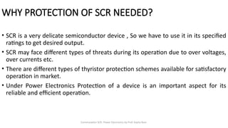
WHY PROTECTION OF SCR NEEDED?
• SCR is a very delicate semiconductor device , So we have to use it in its specified
ratings to get desired output.
• SCR may face different types of threats during its operation due to over voltages,
over currents etc.
• There are different types of thyristor protection schemes available for satisfactory
operation in market.
• Under Power Electronics Protection of a device is an important aspect for its
reliable and efficient operation.
5.
Commutation SCR- PowerElectronics by Prof. Kavita Bani
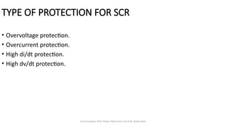
TYPE OF PROTECTION FOR SCR
• Overvoltage protection.
• Overcurrent protection.
• High di/dt protection.
• High dv/dt protection.
6.
Commutation SCR- PowerElectronics by Prof. Kavita Bani
OVERVOLTAGE PROTECTION
• A thyristor may be subjected to internal or external over- voltages.
• Internal Over-Voltages : After commutation of a thyristor reverse recovery current decays
abruptly with high di/dt which causes a high reverse voltage [as, V = L(di/dt) so if di/dt is
high then V will be large] that can exceed the rated break-over voltage and the device
may be damaged.
• External Over-Voltages : These are caused due to various reasons in the supply line like
lightning, surge conditions (abnormal voltage spike) etc. External over voltage may cause
different types of problem in thyristor operation like increase in leakage current,
permanent breakdown of junctions, unwanted turn-on of devices etc. So, we have to
suppress the over-voltages.
7.
Commutation SCR- PowerElectronics by Prof. Kavita Bani
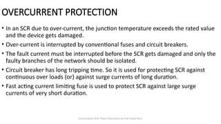
OVERCURRENT PROTECTION
• In an SCR due to over-current, the junction temperature exceeds the rated value
and the device gets damaged.
• Over-current is interrupted by conventional fuses and circuit breakers.
• The fault current must be interrupted before the SCR gets damaged and only the
faulty branches of the network should be isolated.
• Circuit breaker has long tripping time. So it is used for protecting SCR against
continuous over loads (or) against surge currents of long duration.
• Fast acting current limiting fuse is used to protect SCR against large surge
currents of very short duration.
8.
Commutation SCR- PowerElectronics by Prof. Kavita Bani
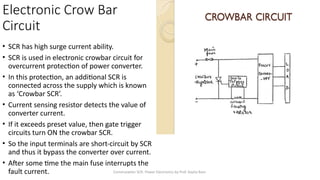
Electronic Crow Bar
Circuit
• SCR has high surge current ability.
• SCR is used in electronic crowbar circuit for
overcurrent protection of power converter.
• In this protection, an additional SCR is
connected across the supply which is known
as ‘Crowbar SCR’.
• Current sensing resistor detects the value of
converter current.
• If it exceeds preset value, then gate trigger
circuits turn ON the crowbar SCR.
• So the input terminals are short-circuit by SCR
and thus it bypass the converter over current.
• After some time the main fuse interrupts the
fault current.
9.
Commutation SCR- PowerElectronics by Prof. Kavita Bani
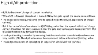
High di/dt protection.
• di/dt is the rate of change of current in a device.
• When SCR is forward biased and is turned ON by the gate signal, the anode current flows.
• The anode current requires some time to spread inside the device. (Spreading of charge
carriers)
• But if the rate of rise of anode current(di/dt) is greater than the spread velocity of charge
carriers then local hot spots is created near the gate due to increased current density. This
localised heating may damage the device.
• Local spot heating is avoided by ensuring that the conduction spreads to the whole area
very rapidly. (OR) The di/dt value must be maintained below a threshold (limiting) value.
• This is done by means of connecting an inductor in series with the thyristor.
10.
Commutation SCR- PowerElectronics by Prof. Kavita Bani
High di/dt protection.
• The inductance L opposes the high di/dt variations.
• When the current variation is high, the inductor smooths it and
protects the SCR from damage. (Though di/dt variation is high, the
inductor ‘L’ smooths it because it takes some time to charge).
• L [Vs / (di/dt)]
≥
11.
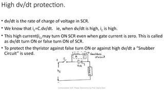
Commutation SCR- PowerElectronics by Prof. Kavita Bani
• dv/dt is the rate of charge of voltage in SCR.
• We know that iC=C.dv/dt. ie, when dv/dt is high, iC is high.
• This high current(iC) may turn ON SCR even when gate current is zero. This is called
as dv/dt turn ON or false turn ON of SCR.
• To protect the thyristor against false turn ON or against high dv/dt a “Snubber
Circuit” is used.
High dv/dt protection.
12.
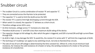
Commutation SCR- PowerElectronics by Prof. Kavita Bani
Snubber circuit
• The snubber Circuit is a series combination of resistor ‘R’ and capacitor ‘C’.
• They are connected across the thyristor to be protected.
• The capacitor ‘C’ is used to limit the dv/dt across the SCR.
• The resistor ‘R’ is used to limit high discharging current through the SCR.
• When switch S is closed, the capacitor ‘C’ behaves as a short-circuit.
• Therefore voltage across SCR is zero.
• As time increases, voltage across ‘C’ increases at a slow rate.
• Therefore dv/dt across ‘C’ and SCR is less than maximum dv/dt rating of the device.
• The capacitor charges to full voltage Vs; after which the gate is triggered, and SCR is turned ON and high current flows
through SCR.
• As di/dt is high, it may damage the SCR. To avoid this, the resistor R in series with ‘C’ will limit the magnitude of di/dt.
• The technique of ‘snubbing’ can apply to any switching circuit, not only to thyristor/triac circuits.
• The rate of rise of turn-off voltage is determined by the time constant RLC. Where RL is the circuit minimum load
resistance, for instance the cold resistance of a heater or lamp, the winding resistance of a motor or the primary
resistance of a transformer.

![Commutation SCR- Power Electronics by Prof. Kavita Bani
OVERVOLTAGE PROTECTION
• A thyristor may be subjected to internal or external over- voltages.
• Internal Over-Voltages : After commutation of a thyristor reverse recovery current decays
abruptly with high di/dt which causes a high reverse voltage [as, V = L(di/dt) so if di/dt is
high then V will be large] that can exceed the rated break-over voltage and the device
may be damaged.
• External Over-Voltages : These are caused due to various reasons in the supply line like
lightning, surge conditions (abnormal voltage spike) etc. External over voltage may cause
different types of problem in thyristor operation like increase in leakage current,
permanent breakdown of junctions, unwanted turn-on of devices etc. So, we have to
suppress the over-voltages.](https://image.slidesharecdn.com/pelecture10-260113092019-ed59319e/85/Power-Electronics_PE_lecture_10_presentation-pptx-6-320.jpg)
![Commutation SCR- Power Electronics by Prof. Kavita Bani
High di/dt protection.
• The inductance L opposes the high di/dt variations.
• When the current variation is high, the inductor smooths it and
protects the SCR from damage. (Though di/dt variation is high, the
inductor ‘L’ smooths it because it takes some time to charge).
• L [Vs / (di/dt)]
≥](https://image.slidesharecdn.com/pelecture10-260113092019-ed59319e/85/Power-Electronics_PE_lecture_10_presentation-pptx-10-320.jpg)