This document provides instructions for disassembling and assembling various components of 402D-05, 403D-07, 403D-11, 403D-15, 403D-15T, 403D-17, 404D-15, 404D-22, 404D-22T, and 404D-22TA industrial engine models. The document covers procedures such as removing and installing the fuel filter base, fuel transfer pump, fuel lines, and other fuel system components, as well as servicing cooling system, valve train, cylinder head, crankshaft, and electrical parts. Safety warnings are provided throughout regarding hazards and preventing contamination.
This is the Highly Detailed factory service repair manual for thePERKINS 1100 SERIES 1104D INDUSTRIAL ENGINE (MODEL NJ), this Service Manual has detailed illustrations as well as step by step instructions,It is 100 percents complete and intact. they are specifically written for the do-it-yourself-er as well as the experienced mechanic.PERKINS 1100 SERIES 1104D INDUSTRIAL ENGINE (MODEL NJ) Service Repair Workshop Manual provides step-by-step instructions based on the complete dis-assembly of the machine. It is this level of detail, along with hundreds of photos and illustrations, that guide the reader through each service and repair procedure. Complete download comes in pdf format which can work under all PC based windows operating system and Mac also, All pages are printable. Using this repair manual is an inexpensive way to keep your vehicle working properly.
Service Repair Manual Covers:
File Format: PDF
Compatible: All Versions of Windows & Mac
Language: English
Requirements: Adobe PDF Reader
NO waiting, Buy from responsible seller and get INSTANT DOWNLOAD, Without wasting your hard-owned money on uncertainty or surprise! All pages are is great to havePERKINS 1100 SERIES 1104D INDUSTRIAL ENGINE (MODEL NJ) Service Repair Workshop Manual.
Looking for some other Service Repair Manual,please check:
https://www.aservicemanualpdf.com/
Thanks for visiting!
8
Core technology of Hyundai Motor Group's EV platform 'E-GMP'Hyundai Motor Group
What’s the force behind Hyundai Motor Group's EV performance and quality?
Maximized driving performance and quick charging time through high-density battery pack and fast charging technology and applicable to various vehicle types!
Discover more about Hyundai Motor Group’s EV platform ‘E-GMP’!
𝘼𝙣𝙩𝙞𝙦𝙪𝙚 𝙋𝙡𝙖𝙨𝙩𝙞𝙘 𝙏𝙧𝙖𝙙𝙚𝙧𝙨 𝙞𝙨 𝙫𝙚𝙧𝙮 𝙛𝙖𝙢𝙤𝙪𝙨 𝙛𝙤𝙧 𝙢𝙖𝙣𝙪𝙛𝙖𝙘𝙩𝙪𝙧𝙞𝙣𝙜 𝙩𝙝𝙚𝙞𝙧 𝙥𝙧𝙤𝙙𝙪𝙘𝙩𝙨. 𝙒𝙚 𝙝𝙖𝙫𝙚 𝙖𝙡𝙡 𝙩𝙝𝙚 𝙥𝙡𝙖𝙨𝙩𝙞𝙘 𝙜𝙧𝙖𝙣𝙪𝙡𝙚𝙨 𝙪𝙨𝙚𝙙 𝙞𝙣 𝙖𝙪𝙩𝙤𝙢𝙤𝙩𝙞𝙫𝙚 𝙖𝙣𝙙 𝙖𝙪𝙩𝙤 𝙥𝙖𝙧𝙩𝙨 𝙖𝙣𝙙 𝙖𝙡𝙡 𝙩𝙝𝙚 𝙛𝙖𝙢𝙤𝙪𝙨 𝙘𝙤𝙢𝙥𝙖𝙣𝙞𝙚𝙨 𝙗𝙪𝙮 𝙩𝙝𝙚 𝙜𝙧𝙖𝙣𝙪𝙡𝙚𝙨 𝙛𝙧𝙤𝙢 𝙪𝙨.
Over the 10 years, we have gained a strong foothold in the market due to our range's high quality, competitive prices, and time-lined delivery schedules.
Fleet management these days is next to impossible without connected vehicle solutions. Why? Well, fleet trackers and accompanying connected vehicle management solutions tend to offer quite a few hard-to-ignore benefits to fleet managers and businesses alike. Let’s check them out!
Symptoms like intermittent starting and key recognition errors signal potential problems with your Mercedes’ EIS. Use diagnostic steps like error code checks and spare key tests. Professional diagnosis and solutions like EIS replacement ensure safe driving. Consult a qualified technician for accurate diagnosis and repair.
Things to remember while upgrading the brakes of your carjennifermiller8137
Upgrading the brakes of your car? Keep these things in mind before doing so. Additionally, start using an OBD 2 GPS tracker so that you never miss a vehicle maintenance appointment. On top of this, a car GPS tracker will also let you master good driving habits that will let you increase the operational life of your car’s brakes.
5 Warning Signs Your BMW's Intelligent Battery Sensor Needs AttentionBertini's German Motors
IBS monitors and manages your BMW’s battery performance. If it malfunctions, you will have to deal with an array of electrical issues in your vehicle. Recognize warning signs like dimming headlights, frequent battery replacements, and electrical malfunctions to address potential IBS issues promptly.
What Exactly Is The Common Rail Direct Injection System & How Does It WorkMotor Cars International
Learn about Common Rail Direct Injection (CRDi) - the revolutionary technology that has made diesel engines more efficient. Explore its workings, advantages like enhanced fuel efficiency and increased power output, along with drawbacks such as complexity and higher initial cost. Compare CRDi with traditional diesel engines and discover why it's the preferred choice for modern engines.
What Does the PARKTRONIC Inoperative, See Owner's Manual Message Mean for You...Autohaus Service and Sales
Learn what "PARKTRONIC Inoperative, See Owner's Manual" means for your Mercedes-Benz. This message indicates a malfunction in the parking assistance system, potentially due to sensor issues or electrical faults. Prompt attention is crucial to ensure safety and functionality. Follow steps outlined for diagnosis and repair in the owner's manual.
Comprehensive program for Agricultural Finance, the Automotive Sector, and Empowerment . We will define the full scope and provide a detailed two-week plan for identifying strategic partners in each area within Limpopo, including target areas.:
1. Agricultural : Supporting Primary and Secondary Agriculture
• Scope: Provide support solutions to enhance agricultural productivity and sustainability.
• Target Areas: Polokwane, Tzaneen, Thohoyandou, Makhado, and Giyani.
2. Automotive Sector: Partnerships with Mechanics and Panel Beater Shops
• Scope: Develop collaborations with automotive service providers to improve service quality and business operations.
• Target Areas: Polokwane, Lephalale, Mokopane, Phalaborwa, and Bela-Bela.
3. Empowerment : Focusing on Women Empowerment
• Scope: Provide business support support and training to women-owned businesses, promoting economic inclusion.
• Target Areas: Polokwane, Thohoyandou, Musina, Burgersfort, and Louis Trichardt.
We will also prioritize Industrial Economic Zone areas and their priorities.
Sign up on https://profilesmes.online/welcome/
To be eligible:
1. You must have a registered business and operate in Limpopo
2. Generate revenue
3. Sectors : Agriculture ( primary and secondary) and Automative
Women and Youth are encouraged to apply even if you don't fall in those sectors.
Why Is Your BMW X3 Hood Not Responding To Release CommandsDart Auto
Experiencing difficulty opening your BMW X3's hood? This guide explores potential issues like mechanical obstruction, hood release mechanism failure, electrical problems, and emergency release malfunctions. Troubleshooting tips include basic checks, clearing obstructions, applying pressure, and using the emergency release.
In this presentation, we have discussed a very important feature of BMW X5 cars… the Comfort Access. Things that can significantly limit its functionality. And things that you can try to restore the functionality of such a convenient feature of your vehicle.
Perkins 400 series 402 d 403d 404d industrial engine (model gj) service repair manual
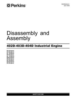
1. KENR6226-01
April 2008
Disassembly and
Assembly
402D-403D-404D Industrial Engine
GG (Engine)
GH (Engine)
GJ (Engine)
GK (Engine)
GL (Engine)
GM (Engine)
GN (Engine)
GP (Engine)
GQ (Engine)
GS (Engine)
SAFETY.CAT.COM
This document has been printed from SPI². Not for Resale
2. Important Safety Information
Most accidents that involve product operation, maintenance and repair are caused by failure to
observe basic safety rules or precautions. An accident can often be avoided by recognizing potentially
hazardous situations before an accident occurs. A person must be alert to potential hazards. This
person should also have the necessary training, skills and tools to perform these functions properly.
Improper operation, lubrication, maintenance or repair of this product can be dangerous and
could result in injury or death.
Do not operate or perform any lubrication, maintenance or repair on this product, until you have
read and understood the operation, lubrication, maintenance and repair information.
Safety precautions and warnings are provided in this manual and on the product. If these hazard
warnings are not heeded, bodily injury or death could occur to you or to other persons.
The hazards are identified by the “Safety Alert Symbol” and followed by a “Signal Word” such as
“DANGER”, “WARNING” or “CAUTION”. The Safety Alert “WARNING” label is shown below.
The meaning of this safety alert symbol is as follows:
Attention! Become Alert! Your Safety is Involved.
The message that appears under the warning explains the hazard and can be either written or
pictorially presented.
Operations that may cause product damage are identified by “NOTICE” labels on the product and in
this publication.
Perkins cannot anticipate every possible circumstance that might involve a potential hazard. The
warnings in this publication and on the product are, therefore, not all inclusive. If a tool, procedure,
work method or operating technique that is not specifically recommended by Perkins is used,
you must satisfy yourself that it is safe for you and for others. You should also ensure that the
product will not be damaged or be made unsafe by the operation, lubrication, maintenance or
repair procedures that you choose.
The information, specifications, and illustrations in this publication are on the basis of information that
was available at the time that the publication was written. The specifications, torques, pressures,
measurements, adjustments, illustrations, and other items can change at any time. These changes can
affect the service that is given to the product. Obtain the complete and most current information before
you start any job. Perkins dealers or Perkins distributors have the most current information available.
When replacement parts are required for this
product Perkins recommends using Perkins
replacement parts.
Failure to heed this warning can lead to prema-
ture failures, product damage, personal injury or
death.
This document has been printed from SPI². Not for Resale
3. KENR6226-01 3
Table of Contents
Table of Contents
Disassembly and Assembly Section
Fuel Filter Base - Remove and Install (403D-11,
403D-15, 403D-15T, 403D-17, 404D-15, 404D-22,
404D-22T and 404D-22TA Engines) ..................... 4
Fuel Filter Base - Remove and Install (402D-05 and
403D-07 Engines) ................................................. 5
Fuel Transfer Pump - Remove and Install (Mechanical
Fuel Transfer Pump) ............................................. 7
Fuel Transfer Pump - Remove and Install (Electrical
Fuel Transfer Pump) ............................................. 8
Fuel Injection Lines - Remove and Install .............. 9
Fuel Shutoff Solenoid - Remove and Install ........ 12
Fuel Injection Pump - Remove and Install ........... 13
Fuel Injector - Remove and Install ....................... 15
Turbocharger - Remove and Install ..................... 16
Exhaust Manifold - Remove and Install ............... 18
Inlet and Exhaust Valve Springs - Remove and
Install ................................................................... 19
Inlet and Exhaust Valves - Remove and Install .... 22
Engine Oil Line - Remove and Install ................... 24
Engine Oil Cooler - Remove and Install ............... 26
Engine Oil Relief Valve - Remove and Install ....... 27
Engine Oil Pump - Remove .................................. 28
Engine Oil Pump - Install ...................................... 30
Water Pump - Remove and Install (403D-11,
403D-15, 403D-15T, 403D-17, 404D-15, 404D-22,
404D-22T and 404D-22TA Engines) ................... 32
Water Pump - Remove and Install (402D-05 and
403D-07 Engines) ............................................... 33
Water Temperature Regulator Housing - Remove and
Install .................................................................. 35
Water Temperature Regulator - Remove and Install
(402D-05 and 404D-07 Engines) ........................ 36
Water Temperature Regulator - Remove and Install
(403D-11, 403D-15, 403D-15T, 403D-17, 404D-15,
404D-22, 404D-22T and 404D-22TA Engines) ... 38
Flywheel - Remove ............................................... 39
Flywheel - Install ................................................... 40
Crankshaft Rear Seal - Remove and Install ......... 41
Crankshaft Wear Sleeve (Rear) - Remove and
Install ................................................................... 43
Flywheel Housing - Remove and Install .............. 44
Flywheel Housing - Remove and Install (Engines with
Flywheel Housing and Back Plate) ..................... 45
Crankshaft Pulley - Remove and Install ............... 47
Crankshaft Front Seal - Remove and Install ......... 48
Housing (Front) - Remove .................................... 49
Housing (Front) - Disassemble ............................. 50
Housing (Front) - Assemble .................................. 52
Housing (Front) - Install ........................................ 55
Crankcase Breather - Remove and Install
(Turbocharged Engines) ..................................... 56
Crankcase Breather - Remove and Install (Naturally
Aspirated Engines) .............................................. 58
Valve Mechanism Cover - Remove and Install ..... 60
Rocker Shaft and Pushrod - Remove ................... 62
Rocker Shaft - Disassemble (403D-15, 403D-15T,
403D-17, 404D-22, 404D-22T and 404D-22TA
Engines) .............................................................. 62
Rocker Shaft - Disassemble (402D-05, 403D-07,
403D-11 and 404D-15 Engines) ......................... 63
Rocker Shaft - Assemble (403D-15,
403D-15T,403D-17, 404D-22, 404D-22T and
404D-22TA Engines) ........................................... 64
Rocker Shaft - Assemble (402D-05, 403D-07,
403D-11 and 404D-15 Engines) ......................... 65
Rocker Shaft and Pushrod - Install ....................... 66
Cylinder Head - Remove ...................................... 67
Cylinder Head - Install .......................................... 69
Lifter Group - Remove and Install ......................... 71
Camshaft - Remove .............................................. 72
Camshaft - Disassemble ....................................... 73
Camshaft - Assemble ........................................... 74
Camshaft - Install .................................................. 74
Engine Oil Pan - Remove and Install ................... 76
Pistons and Connecting Rods - Remove .............. 77
Pistons and Connecting Rods - Disassemble ....... 78
Pistons and Connecting Rods - Assemble ........... 80
Pistons and Connecting Rods - Install .................. 81
Connecting Rod Bearings - Remove (Connecting
rods in position) ................................................... 83
Connecting Rod Bearings - Install (Connecting rods
in position) ........................................................... 83
Connecting Rod Bearings - Install ........................ 84
Crankshaft Main Bearings - Remove .................... 85
Crankshaft Main Bearings - Install ........................ 86
Crankshaft - Remove ............................................ 88
Crankshaft - Install ................................................ 89
Bearing Clearance - Check ................................... 90
Coolant Temperature Switch - Remove and Install
(403D-11, 403D-15, 403D-15T, 403D-17, 404D-15,
404D-22, 404D-22T and 404D-22TA Engines) ... 91
Coolant Temperature Switch - Remove and Install
(402D-05 and 403D-07 Engines) ........................ 92
Engine Oil Pressure Switch - Remove and Install
............................................................................. 93
Glow Plugs - Remove and Install ......................... 95
V-Belts - Remove and Install ................................ 96
Fan - Remove and Install ..................................... 96
Alternator - Remove and Install (65 Amp and 85 Amp
Alternators) ......................................................... 97
Alternator - Remove and Install (55 Amp
Alternator) ........................................................... 99
Alternator - Remove and Install (40 Amp
Alternator) ........................................................... 99
Alternator - Remove and Install (14 Amp and 15 Amp
Alternators) ....................................................... 101
Electric Starting Motor - Remove and Install ..... 102
Index Section
Index ................................................................... 103
This document has been printed from SPI². Not for Resale
4. 4 KENR6226-01
Disassembly and Assembly Section
Disassembly and Assembly
Section
i02959949
Fuel Filter Base - Remove and
Install
(403D-11, 403D-15, 403D-15T,
403D-17, 404D-15, 404D-22,
404D-22T and 404D-22TA
Engines)
Removal Procedure
NOTICE
Do not allow dirt to enter the fuel system. Thoroughly
clean the area around a fuel system component that
will be disconnected. Fit a suitable cover over discon-
nected fuel system component.
NOTICE
Care must be taken to ensure that fluids are contained
during performance of inspection, maintenance, test-
ing, adjusting and repair of the product. Be prepared to
collect the fluid with suitable containers before open-
ing any compartment or disassembling any compo-
nent containing fluids.
Dispose of all fluids according to local regulations and
mandates.
NOTICE
Keep all parts clean from contaminants.
Contaminants may cause rapid wear and shortened
component life.
Note: Place identification marks on all hoses for
installation purposes. Plug all hoses and all the ports
in the fuel filter base. This helps prevent fluid loss,
and this helps to keep contaminants from entering
the system.
1. Turn the fuel supply to the OFF position.
g01302737
Illustration 1
Typical example
2. Loosen hose clamps (4) and disconnect hoses (5).
3. If necessary, remove fuel filter element (7)
from fuel filter base (1). Refer to Operation
and Maintenance Manual, “Fuel System Filter -
Replace”.
4. Remove fasteners (2) and remove fuel filter base
(1) from the mounting bracket.
5. If necessary, remove plugs (6) and washers (not
shown) from fuel filter base (1). Remove tube
assemblies (3) and rubber olives (not shown) from
fuel filter base (1).
Installation Procedure
NOTICE
Keep all parts clean from contaminants.
Contaminants may cause rapid wear and shortened
component life.
Note: If the engine is equipped with a hand priming
pump, the hand priming pump is mounted on the fuel
filter base. The assembly of the fuel filter base and
the hand priming pump is not serviceable.
1. Ensure that the fuel filter base is clean and free
from damage. If necessary, replace the fuel filter
base.
This document has been printed from SPI². Not for Resale
5. KENR6226-01 5
Disassembly and Assembly Section
g01302737
Illustration 2
Typical example
2. If necessary, install new rubber olives (not shown)
onto tube assemblies (3). Install tube assemblies
(3) to fuel filter base (1). Ensure the correct
orientation of the tube assemblies. Tighten the
nuts to a torque of 9 N·m (80 lb in).
3. Install washers (not shown) onto plugs (6). Install
plugs (6) to fuel filter base (1). Tighten the plugs
to a torque of 23 N·m (17 lb ft).
4. Align fuel filter base (1) with the mounting bracket.
Install fasteners (2). Tighten the fasteners to a
torque of 50 N·m (37 lb ft).
5. If necessary, install a new fuel filter element
(7) to fuel filter base (1). Refer to Operation
and Maintenance Manual, “Fuel System Filter -
Replace”.
6. Connect hoses (5) and tighten hose clamps (4).
Note: Ensure that the hoses do not contact any other
engine components.
7. Turn the fuel supply to the ON position.
8. Remove the air from the fuel system. Refer to
Operation and Maintenance Manual, “Fuel System
- Prime”.
i02645711
Fuel Filter Base - Remove and
Install
(402D-05 and 403D-07 Engines)
Removal Procedure
NOTICE
Do not allow dirt to enter the fuel system. Thoroughly
clean the area around a fuel system component that
will be disconnected. Fit a suitable cover over discon-
nected fuel system component.
NOTICE
Care must be taken to ensure that fluids are contained
during performance of inspection, maintenance, test-
ing, adjusting and repair of the product. Be prepared to
collect the fluid with suitable containers before open-
ing any compartment or disassembling any compo-
nent containing fluids.
Dispose of all fluids according to local regulations and
mandates.
NOTICE
Keep all parts clean from contaminants.
Contaminants may cause rapid wear and shortened
component life.
Note: Place identification marks on all hoses for
installation purposes. Plug all hoses and all the ports
in the fuel filter base. This helps prevent fluid loss,
and this helps to keep contaminants from entering
the system.
1. Turn the fuel supply to the OFF position.
This document has been printed from SPI². Not for Resale
6. 6 KENR6226-01
Disassembly and Assembly Section
g01303701
Illustration 3
Typical example
2. Loosen hose clamps (3) and disconnect hoses (4).
3. If necessary, remove fuel filter element (5). Refer
to Operations and Maintenance Manual, “Fuel
System Filter - Replace”.
4. Remove bolt (1) and remove fuel filter base (2)
from the mounting bracket.
Installation Procedure
NOTICE
Keep all parts clean from contaminants.
Contaminants may cause rapid wear and shortened
component life.
1. Ensure that the fuel filter base is clean and free
from damage. If necessary, replace the fuel filter
base.
g01303701
Illustration 4
Typical example
2. Align fuel filter base (2) with the mounting bracket.
Install bolt (1). Tighten the bolt to a torque of
25 N·m (18 lb ft).
3. If necessary, install a new fuel filter element
(6) to fuel filter base (2). Refer to Operation
and Maintenance Manual, “Fuel System Filter -
Replace”.
4. Connect hoses (4) and tighten hose clamps (3).
Note: Ensure that the hoses do not contact any other
engine components.
5. Turn the fuel supply to the ON position.
6. Remove the air from the fuel system. Refer to
Operation and Maintenance Manual, “Fuel System
- Prime”.
This document has been printed from SPI². Not for Resale
7. KENR6226-01 7
Disassembly and Assembly Section
i02645722
Fuel Transfer Pump - Remove
and Install
(Mechanical Fuel Transfer
Pump)
Removal Procedure
NOTICE
Do not allow dirt to enter the fuel system. Thoroughly
clean the area around a fuel system component that
will be disconnected. Fit a suitable cover over discon-
nected fuel system component.
NOTICE
Care must be taken to ensure that fluids are contained
during performance of inspection, maintenance, test-
ing, adjusting and repair of the product. Be prepared to
collect the fluid with suitable containers before open-
ing any compartment or disassembling any compo-
nent containing fluids.
Dispose of all fluids according to local regulations and
mandates.
NOTICE
Keep all parts clean from contaminants.
Contaminants may cause rapid wear and shortened
component life.
Note: Place identification marks on all hoses for
installation purposes. Plug all hoses and all the
ports in the fuel transfer pump. This helps prevent
fluid loss, and this helps to keep contaminants from
entering the system.
1. Turn the fuel supply to the OFF position.
g01326306
Illustration 5
Typical example
Note: The fuel transfer pump can be oriented in two
positions. Before removing the fuel transfer pump
from the cylinder block, note the orientation of flange
(5) on fuel transfer pump (1) for assembly.
2. Loosen the hose clamps and disconnect the
hoses (not shown) from fuel transfer pump (1).
3. Evenly loosen bolts (4) and remove fuel transfer
pump (1) from the cylinder block.
Note: In order to remove the fuel transfer pump, it
may be necessary to rotate the crankshaft until the
operating plunger of the fuel transfer pump is not
under pressure.
4. Remove O-ring seal (3) from fuel transfer pump
(1).
Installation Procedure
NOTICE
Keep all parts clean from contaminants.
Contaminants may cause rapid wear and shortened
component life.
This document has been printed from SPI². Not for Resale
8. 8 KENR6226-01
Disassembly and Assembly Section
g01326306
Illustration 6
Typical example
1. Clean the mating surfaces of the cylinder block
and flange (5) on the fuel transfer pump.
Note: Ensure that the camshaft lobe for the fuel
transfer pump is at minimum lift before the fuel
transfer pump is installed. The fuel transfer pump
can be oriented in two positions. Ensure that the fuel
transfer pump is oriented in the correct position.
2. Install a new O-ring seal (3) to fuel transfer pump
(1).
3. Lubricate the operating plunger of fuel transfer
pump (1) with clean engine oil.
4. Position fuel transfer pump (1) on the cylinder
block. Ensure that the operating plunger is
positioned correctly on the camshaft lobe. Install
bolts (4). Tighten the bolts to a torque of 6 N·m
(53 lb in).
5. Connect the hoses (not shown) to fuel transfer
pump (1). Tighten the hose clamps.
Note: The inlet for the fuel transfer pump can be
rotated 360 degrees by loosening bolt (2). The
fuel inlet is adjustable in 15 degree increments. If
adjustment is made to the position of the fuel inlet,
tighten bolt (2) to a torque of 2.5 N·m (22 lb in).
6. Turn the fuel supply to the ON position.
7. Prime the fuel system. Refer to Systems
Operation, Testing and Adjusting, “Fuel System -
Prime” for additional information.
i02645719
Fuel Transfer Pump - Remove
and Install
(Electrical Fuel Transfer Pump)
Removal Procedure
NOTICE
Care must be taken to ensure that fluids are contained
during performance of inspection, maintenance, test-
ing, adjusting and repair of the product. Be prepared to
collect the fluid with suitable containers before open-
ing any compartment or disassembling any compo-
nent containing fluids.
Dispose of all fluids according to local regulations and
mandates.
NOTICE
Keep all parts clean from contaminants.
Contaminants may cause rapid wear and shortened
component life.
Note: Put identification marks on all hoses, on all
hose assemblies, on wires and on all tube assemblies
for installation purposes. Plug all hose assemblies
and tube assemblies. This helps to prevent fluid loss
and this helps to keep contaminants from entering
the system.
1. Turn the fuel supply to the OFF position.
2. Turn the battery disconnect switch to the OFF
position.
g01304057
Illustration 7
Typical example
3. Disconnect harness assembly (1).
This document has been printed from SPI². Not for Resale
9. KENR6226-01 9
Disassembly and Assembly Section
4. Loosen hose clamps (4) and (5). Disconnect
hoses (6) and (7).
5. Remove bolts (2) and remove electric transfer
pump (3).
Installation Procedure
1. Ensure that the electric transfer pump is clean
and free from damage. If necessary, replace the
electric transfer pump.
g01304057
Illustration 8
Typical example
2. Position electric transfer pump (3) on the mounting
and install bolts (2).
3. Tighten bolts (2) to a torque of 9 N·m (79 lb in).
4. Connect hoses (6) and (7). Tighten hose clamps
(4) and (5).
5. Connect harness assembly (1).
6. Turn the fuel supply to the ON position.
7. Turn the battery disconnect switch to the ON
position.
8. Remove the air from the fuel system. Refer to
Operation and Maintenance Manual, “Fuel System
- Prime”.
i02959953
Fuel Injection Lines - Remove
and Install
Removal Procedure
NOTICE
Keep all parts clean from contaminants.
Contaminants may cause rapid wear and shortened
component life.
NOTICE
Care must be taken to ensure that fluids are contained
during performance of inspection, maintenance, test-
ing, adjusting and repair of the product. Be prepared to
collect the fluid with suitable containers before open-
ing any compartment or disassembling any compo-
nent containing fluids.
Dispose of all fluids according to local regulations and
mandates.
NOTICE
Do not let the tops of fuel injectors turn when the fuel
line nuts are loosened or tightened.
The fuel injectors will be damaged if the top of the
injector turns in the body.
The engine will be damaged if a defective fuel injector
is used because the shape of fuel (spray pattern) that
comes out of the nozzle will not be correct.
Note: Place identification marks on all tube
assemblies for installation. Plug all lines and tube
assemblies in order to prevent contamination.
1. Turn the fuel supply to the OFF position.
This document has been printed from SPI². Not for Resale
10. 10 KENR6226-01
Disassembly and Assembly Section
g01326550
Illustration 9
Typical example
2. Disconnect nuts (1) for fuel injection lines (2) from
the fuel injectors.
3. Disconnect nuts (1) for fuel injection lines (2) from
the fuel injection pump.
4. Remove fuel injection lines (2) from the engine
as a unit.
5. Use suitable caps in order to plug the open ports
of the fuel injection pump immediately.
6. The 403D-15, 403D-15T, 403D-17, 404D-22,
404D-22T and 404D-22TA engines have a rigid
fuel return line.
For engines with a rigid fuel return line, remove
banjo bolt (4) from fuel return line (3). Remove
washers (8).
The 402D-05, 403D-07, 403D-11 and 404D-15
engines have a flexible fuel return hose.
For engines with a flexible fuel return hose,
disconnect the hose from the fuel injection pump.
g01326555
Illustration 10
Typical example
7. Remove nuts (5) from fuel injectors (7).
Note: For engines with a rigid fuel return line, ensure
that the fuel return line is not distorted when the nuts
are loosened.
8. Remove fuel return line (3) and washers (6) from
fuel injectors (7).
9. Use suitable caps in order to plug the fuel injectors
immediately.
Installation Procedure
Table 1
Required Tools
Tool
Part
Number
Part Name Qty
A 27610294 Injector Pipe Nut Tool 1
NOTICE
Keep all parts clean from contaminants.
Contaminants may cause rapid wear and shortened
component life.
This document has been printed from SPI². Not for Resale
11. KENR6226-01 11
Disassembly and Assembly Section
NOTICE
Do not let the tops of fuel injectors turn when the fuel
line nuts are loosened or tightened.
The fuel injectors will be damaged if the top of the
injector turns in the body.
The engine will be damaged if a defective fuel injector
is used because the shape of fuel (spray pattern) that
comes out of the nozzle will not be correct.
Note: The installation procedure is similar for the
two cylinder, the three cylinder and the four cylinder
engines.
g01326555
Illustration 11
Typical example
1. Remove the caps from fuel injectors (7). Install
new washers (6) and fuel return line (3) to fuel
injectors (7).
Note: The washers (6) have two small holes.
2. Install nuts (5) to fuel injectors (7).
3. The 403D-15, 403D-15T, 403D-17, 404D-22,
404D-22TA and 404D-22TA engines have a rigid
fuel return line.
For engines with a rigid fuel return line, install new
washers (8) to fuel return line (3) and install banjo
bolt (4) to the fuel injection pump. Tighten banjo
bolt (4) to a torque of 7 N·m (62 lb in).
The 402D-05, 403D-07, 403D-11 and 404D-15
engines have a flexible fuel return hose.
For engines with a flexible fuel return hose,
connect the fuel return hose to the fuel injection
pump.
4. Tighten nuts (5) to a torque of 27 N·m (20 lb ft).
g01326550
Illustration 12
Typical example
5. Remove the caps from the outlet connections of
the fuel injection pump. Install the fuel injection
lines to the engine as a unit.
6. Connect fuel injection lines (2) to fuel injectors (7).
Tighten the union nuts (1) finger tight.
7. Use Tooling (A) to tighten union nuts (1) at the fuel
injection pump.
For 402D-05 and 403D-07 engines, tighten union
nuts (1) to a torque of 20 N·m (15 lb ft).
For 403D-11, 403D-15, 403D-15T, 403D-17,
404D-15, 404D-22, 404D-22T and 404D-22TA
engines, tighten the union nuts (1) to a torque of
23 N·m (17 lb ft).
Note: For the three cylinder and the four cylinder
engines, tighten the center union nuts first.
8. Use Tooling (A) to tighten union nuts (1) at the fuel
injections.
For 402D-05 and 403D-07 engines, tighten union
nuts (1) to a torque of 20 N·m (15 lb ft).
This document has been printed from SPI². Not for Resale
12. 12 KENR6226-01
Disassembly and Assembly Section
For 403D-11, 403D-15, 403D-15T, 403D-17,
404D-15, 404D-22, 404D-22T and 404D-22TA
engines, tighten the union nuts (1) to a torque of
23 N·m (17 lb ft).
9. Turn the fuel supply to the ON position.
10. Prime the fuel system. Refer to Operation and
Maintenance Manual, “Fuel System - Prime” for
more information.
i02645718
Fuel Shutoff Solenoid -
Remove and Install
Removal Procedure
NOTICE
Care must be taken to ensure that fluids are contained
during performance of inspection, maintenance, test-
ing, adjusting and repair of the product. Be prepared to
collect the fluid with suitable containers before open-
ing any compartment or disassembling any compo-
nent containing fluids.
Dispose of all fluids according to local regulations and
mandates.
NOTICE
Keep all parts clean from contaminants.
Contaminants may cause rapid wear and shortened
component life.
1. Turn the battery disconnect switch to the OFF
position.
g01326564
Illustration 13
Typical example
2. Disconnect electrical connection (3) from
the harness assembly (not shown). Mark all
connections for installation.
3. Remove fuel shutoff solenoid (1) from the fuel
injection pump housing by rotating the fuel shutoff
solenoid in a counterclockwise direction.
4. Remove sealing washer (2) from fuel shutoff
solenoid (1).
Installation Procedure
NOTICE
Keep all parts clean from contaminants.
Contaminants may cause rapid wear and shortened
component life.
g01326564
Illustration 14
Typical example
1. Install sealing washer (2) to fuel shutoff solenoid
(1).
2. Install fuel shutoff solenoid (1) into the fuel
injection pump housing by rotating the fuel shutoff
solenoid in a clockwise direction. Tighten the fuel
shutoff solenoid to a torque of 17 N·m (12 lb ft).
3. Connect electrical connection (3) to the harness
assembly (not shown).
4. Turn the battery disconnect switch to the ON
position.
This document has been printed from SPI². Not for Resale
13. KENR6226-01 13
Disassembly and Assembly Section
i02959957
Fuel Injection Pump - Remove
and Install
Removal Procedure
Start By:
a. Remove the fuel shutoff solenoid. Refer to
Disassembly and Assembly, “Fuel Shutoff
Solenoid - Remove and Install”.
NOTICE
Care must be taken to ensure that fluids are contained
during performance of inspection, maintenance, test-
ing, adjusting and repair of the product. Be prepared to
collect the fluid with suitable containers before open-
ing any compartment or disassembling any compo-
nent containing fluids.
Dispose of all fluids according to local regulations and
mandates.
NOTICE
Keep all parts clean from contaminants.
Contaminants may cause rapid wear and shortened
component life.
Note: The removal procedure is similar for the two
cylinder, the three cylinder and the four cylinder
engines. The Illustrations show a four cylinder engine.
1. Remove the fuel injection lines. Refer to
Disassembly and Assembly, “Fuel Injection Lines
- Remove and Install” for more information.
The 402D-05, 403D-07, 403D-11 and 404D-15
engines have a flexible fuel return hose.
For engines with a flexible fuel return hose,
disconnect the fuel hose from the inlet connection
of the fuel injection pump.
g01327005
Illustration 15
Typical example
g01327006
Illustration 16
Typical example
2. Gradually loosen bolts (4) and nuts (2) that fasten
the fuel injection pump to the cylinder block.
3. Carefully raise fuel injection pump (1) from the
cylinder block and remove clip (7) that connects
link (6) to fuel rack control (5).
4. Remove fuel injection pump (1) from the cylinder
block.
5. Remove shims (3) from the mounting face of the
cylinder block.
This document has been printed from SPI². Not for Resale
14. Thank you very much for
your reading. Please Click
Here. Then Get COMPLETE
MANUAL. NO WAITING
NOTE:
If there is no response to
click on the link above,
please download the PDF
document first and then
click on it.
15. 14 KENR6226-01
Disassembly and Assembly Section
Note: Record the thickness of each shim and the
number of shims for reassembly. The fuel injection
timing is determined by the thickness of the shim
pack that is between the fuel injection pump and
the mounting face on the cylinder block. Refer
to Specifications, “Fuel Injection Pump” for more
information.
Installation Procedure
NOTICE
Keep all parts clean from contaminants.
Contaminants may cause rapid wear and shortened
component life.
Note: The installation procedure is similar for the
two cylinder, the three cylinder and the four cylinder
engines. The Illustrations show a four cylinder engine.
1. Clean the mating surfaces of the cylinder block
and the fuel injection pump.
g01327005
Illustration 17
Typical example
2. New shims (3) must be used during assembly.
Install the correct thickness and the correct
number of shims on the mounting face of the
cylinder block. Refer to Specifications, “Fuel
Injection Pump” for more information.
g01327006
Illustration 18
Typical example
3. Position fuel injection pump (1) close to the
mounting face of the cylinder block, and connect
link (6) and fuel rack control (5) with clip (7).
4. Align fuel injection pump (1) with the studs on the
cylinder block. Install the fuel injection pump to
the cylinder block.
5. Install bolts (4) and nuts (2). Ensure that the
tube clip for the engine oil line is secured by the
appropriate fastener.
For 402D-05, 403D-07, 403D-11 and 404D-15
engines, evenly tighten bolts (4) and nuts (2) to a
torque of 6 N·m (53 lb in).
For 403D-15, 403D-15T, 403D-17, 404D-22,
404D-22T and 404D-22TA engines, evenly tighten
bolts (4) and nuts (2) to a torque of 15 N·m
(11 lb ft).
6. Install the fuel injection lines. Refer to Disassembly
and Assembly, “Fuel Injection Lines - Remove
and Install”.
The 402D-05, 403D-07, 403D-11 and 404D-15
engines have a flexible fuel return hose.
For engines with a flexible fuel return hose,
connect the fuel hose to the inlet connection of
the fuel injection pump.
This document has been printed from SPI². Not for Resale
16. KENR6226-01 15
Disassembly and Assembly Section
End By:
a. Install the fuel shutoff solenoid. Refer to
Disassembly and Assembly, “Fuel Shutoff
Solenoid - Remove and Install”.
i02959963
Fuel Injector - Remove and
Install
Removal Procedure
Start By:
a. Remove the fuel injection lines. Refer to
Disassembly and Assembly, “Fuel Injection Lines
- Remove and Install”.
NOTICE
Care must be taken to ensure that fluids are contained
during performance of inspection, maintenance, test-
ing, adjusting and repair of the product. Be prepared to
collect the fluid with suitable containers before open-
ing any compartment or disassembling any compo-
nent containing fluids.
Dispose of all fluids according to local regulations and
mandates.
NOTICE
Keep all parts clean from contaminants.
Contaminants may cause rapid wear and shortened
component life.
g01320610
Illustration 19
Typical example
1. Use a deep socket to remove fuel injector (1) from
the cylinder head.
2. Remove seat washers (2) from the cylinder head.
Note: 402D-05 and 403D-07 engines have two seat
washers. The seat washers are different diameters.
The 403D-11, 403D-15, 403D-15T, 403D-17,
404D-15, 404D-22, 404D-22T and 404D-22TA
engines have one seat washer.
3. Cap all openings or plug all openings immediately.
Installation Procedure
Table 2
Required Tools
Tool
Part
Number
Part Description Qty
A 1861117
POWERPART
Universal Jointing
Compound
1
NOTICE
Keep all parts clean from contaminants.
Contaminants may cause rapid wear and shortened
component life.
g01304054
Illustration 20
Typical example
1. Clean the bore for the fuel injector in the cylinder
head. Ensure that no debris enters the cylinder.
Clean the threads on the body of the fuel injector.
2. Install new seat washers (2) into the bore for the
fuel injector in the cylinder head.
This document has been printed from SPI². Not for Resale
17. 16 KENR6226-01
Disassembly and Assembly Section
Note: 402D-05 and 403D-07 engines have two seat
washers. The seat washers are different diameters.
The 403D-11, 403D-15, 403D-15T, 403D-17,
404D-15, 404D-22, 404D-22T and 404D-22TA
engines have one seat washer.
3. Apply a bead of Tooling (A) to the first two threads
of the fuel injector that engage into the cylinder
head. The bead should have a diameter of 2 mm
(0.08 inch) and a length of 6 mm (0.25 inch).
Note: Ensure that Tooling (A) does not cover the
body of the fuel injector below the threads.
4. Install fuel injector (1) into the cylinder head. Use a
deep socket to tighten the fuel injector to a torque
of 64 N·m (47 lb ft).
End By:
a. Install the fuel injection lines. Refer to Disassembly
and Assembly, “Fuel Injection Lines - Remove
and Install”.
i02645771
Turbocharger - Remove and
Install
Removal procedure
NOTICE
Care must be taken to ensure that fluids are contained
during performance of inspection, maintenance, test-
ing, adjusting and repair of the product. Be prepared to
collect the fluid with suitable containers before open-
ing any compartment or disassembling any compo-
nent containing fluids.
Dispose of all fluids according to local regulations and
mandates.
NOTICE
Keep all parts clean from contaminants.
Contaminants may cause rapid wear and shortened
component life.
Note: Plug and cap all open ports and tube
assemblies.
g01304121
Illustration 21
g01304528
Illustration 22
1. Loosen hose clamps (5) and remove air inlet hose
(1).
2. Remove allen head screws (21) and remove
exhaust elbow (19) from turbocharger (4). Remove
gasket (18) from the turbocharger.
This document has been printed from SPI². Not for Resale
18. KENR6226-01 17
Disassembly and Assembly Section
3. Remove banjo bolt (2) and washers (3). Remove
the fasteners and the spacers (not shown) for
tube clips (6). Remove bolts (14) and remove tube
assembly (13) from the cylinder block. Remove
O-ring seal (12).
4. Remove bolts (8) and disconnect tube assembly
(10) from the turbocharger. Remove joint (7).
If necessary, remove bolts (9) and remove tube
assembly (10) from the cylinder block. Remove
joint (11).
5. Remove nuts (17) and remove turbocharger (4)
from the exhaust manifold. Remove gasket (20)
from the exhaust manifold. If necessary, remove
studs (15) from the exhaust manifold.
Note: Do not use the actuator rod of the wastegate
to lift the turbocharger.
Installation procedure
NOTICE
Keep all parts clean from contaminants.
Contaminants may cause rapid wear and shortened
component life.
1. Ensure that the turbocharger is clean and free
from damage. Inspect the turbocharger for
wear. If the turbocharger is worn, the complete
turbocharger must be replaced.
2. Test the actuator for correct operation. Refer
to Systems Operation, Testing and Adjusting,
“Wastegate - Test” for more information. If the
actuator is damaged or the actuator does not
operate within the specified limits, the complete
turbocharger must be replaced.
g01304121
Illustration 23
g01304528
Illustration 24
3. Clean the mating surfaces of the exhaust manifold.
If necessary, install studs (15) to the exhaust
manifold. Tighten the studs to a torque of 18 N·m
(13 lb ft). Install a new gasket (20) over the studs.
4. Position turbocharger (4) onto the exhaust
manifold. Install nuts (17) and tighten to a torque
of 25 N·m (18 lb ft).
Note: Do not use the actuator rod of the wastegate
to lift the turbocharger .
This document has been printed from SPI². Not for Resale