Downloaded 35 times
![IJRET: International Journal of Research in Engineering and Technology eISSN: 2319-1163 | pISSN: 2321-7308
_______________________________________________________________________________________________
Volume: 03 Issue: 05 | May-2014, Available @ http://www.ijret.org 517
PERIODIC IMPULSIVE NOISE REDUCTION IN OFDM BASED
POWER LINE COMMUNICATION
Sumi Mathew1
, Prasanth Murukan2
1
M.Tech Scholar, ECE Department, NCERC, Thrissur, Kerala, India
2
Asst. Professor, ECE Department, NCERC, Thrissur, Kerala, India
Abstract
Different communication technologies are used for the transmission of information such as wireless communication, satellite
communication etc. Power Line Communication (PLC) is one of the technologies using existing power cables for the transmission
of information. Power cables are not designed for data transmission. So the PLC environment contains different types of noise.
This paper presents a novel approach for removing periodic impulsive noise from OFDM based power line communication
system. The noise is detected using periodic impulsive noise detection algorithm and the noise is filtered by using adaptive notch
filter. An adaptive filter using LMS algorithm is also designed to suppress periodic impulsive noise. Then compare the Bit Error
Rate (BER) of PLC system without noise filtering, with noise filtering using notch filter and with noise filtering using adaptive
filtering based on LMS algorithm. Results show that the received data is same as that of input data which is transmitted.
Simulation results shows that PLC system after noise filtering gives better results than PLC system without noise filtering.
Key Words: CP (Cyclic Prefix), OFDM, PLC, Periodic Impulsive Noise
---------------------------------------------------------------------***---------------------------------------------------------------------
1. INTRODUCTION
Power Line Communication (PLC) is like any other
communication technologies, i.e, the transmitter modulates
the data before transmission, injects into the channel (power
line channel), and the receiver demodulates the data. PLC
does not require additional cables. It re-uses existing power
cables. Recently the power line communications has been
receiving widespread attention due to its applications in
smart grid (such as automatic meter reading, vehicle to grid
communications), micro inverters, traffic light control,
building automation etc. Power line communication is a
leading technology which uses existing cables for
transmission of signals. So installation cost is less than other
communication approaches. But power cables are originally
designed for supplying power to the electrical appliances.
These electrical appliances also produce noise. The noises in
the low voltage power line has been categorized into five
general classes [1] such as:- coloured background noise;
narrowband noise; periodic impulsive noise asynchronous to
main frequency; periodic impulsive noise synchronous to
main frequency; asynchronous impulsive noise. Coloured
background noise and narrowband noise can be summarized
as background noise. The other noises are impulsive noises
produced by the electrical appliances. i.e, the power line
noises are the summation of background noise and
impulsive noises. The periodic impulsive noises remain
stationary over periods of seconds, minutes or even hours.
This periodic impulsive noise interfered with the transmitted
OFDM signals affect the system performance. So these
impulsive noises must be removed to improve the
performance of the PLC system [2]. OFDM is a multi carrier
modulation technique which is adaptable for several channel
conditions. So the PLC system uses OFDM modulation for
reliable power line communication.
2. OFDM SYSTEM FOR PLC
The OFDM system consist of transmitter section, channel
and receiver section.
OFDM is a multi carrier modulation technique in which the
available spectrum is divided into several sub carriers. It is
based on orthogonality property which allows the
subcarriers are orthogonal to each other. Therefore the cross
talk between co channels can be eliminated. The main
advantage of OFDM over single carrier modulation is its
robustness to narrowband interference and its adaptability to
several channel conditions [3]. Figure 1 shows the OFDM
system for PLC.
2.1 Transmitter
The input bit stream is randomly generated and transmitted
through the OFDM transmitter. Some redundant bits are
added with the generated bit stream for coding purposes. It
is used for error detection and correction. In OFDM system
several coding techniques are used such as block codes,
convolution codes, turbo codes etc. In this system
convolutional coding is used for coding the input data. The
known symbols (also known as pilot symbols) are added
with the OFDM transmitted signals. By using Inverse Fast
Fourier Transform (IFFT) the transmitted data is converted
into orthogonal streams. Cyclic Prefix is inserted to prevent
interference between two overlapping channels. It also
reduces inter symbol interference. This OFDM symbol is
transmitted through the power line channel which contains
noise.](https://image.slidesharecdn.com/periodicimpulsivenoisereductioninofdmbasedpowerlinecommunication-140819063010-phpapp01/75/Periodic-impulsive-noise-reduction-in-ofdm-based-power-line-communication-1-2048.jpg)
![IJRET: International Journal of Research in Engineering and Technology eISSN: 2319-1163 | pISSN: 2321-7308
_______________________________________________________________________________________________
Volume: 03 Issue: 05 | May-2014, Available @ http://www.ijret.org 518
Fig-1: OFDM System for PLC
2.2 Power Line Channel
The data is transmitted through power line channel. Like
any other communication systems, PLC channel also
contains internal and external noise or disturbances. Channel
noise varies with load, frequency, geographic locations etc.
These noise removal technique will be explained later.
Power lines noises are classified into five categories [4].
Coloured background noise-It is caused by
summation of multiple sources of noises with low
power. Its power spectral density decreases with
increasing frequencies.
Narrow band noise-consists of amplitude modulated
sinusoidal signals which is caused by broadcasters,
radio stations etc.
Periodic impulsive noise asynchronous to mains
frequency-It is a kind of impulsive noise which is
caused by switched-mode power supplies.
Periodic impulsive noise synchronous to mains
frequency-which is mainly caused by switching
actions of rectifier diodes found in many electrical
appliances.
Asynchronous impulsive noise-which caused by
switching transients in the power network. First two
types summarized as background noise and last three
types summarized as impulsive noises.
2.3 Receiver
At the receiver the inverse process is performed. The cyclic
prefix is removed and signal is transformed into frequency
domain using Fast Fourier Transform (FFT). Then pilot
symbols are removed and demodulated. After that the data is
decoded to produce the output data. Then the signals are
demodulated to produce the output data. The received data
must be same as that of the transmitted data without any bit
error.
3. PERIODIC IMPULSIVE NOISE DETECTION
ALGORITHM
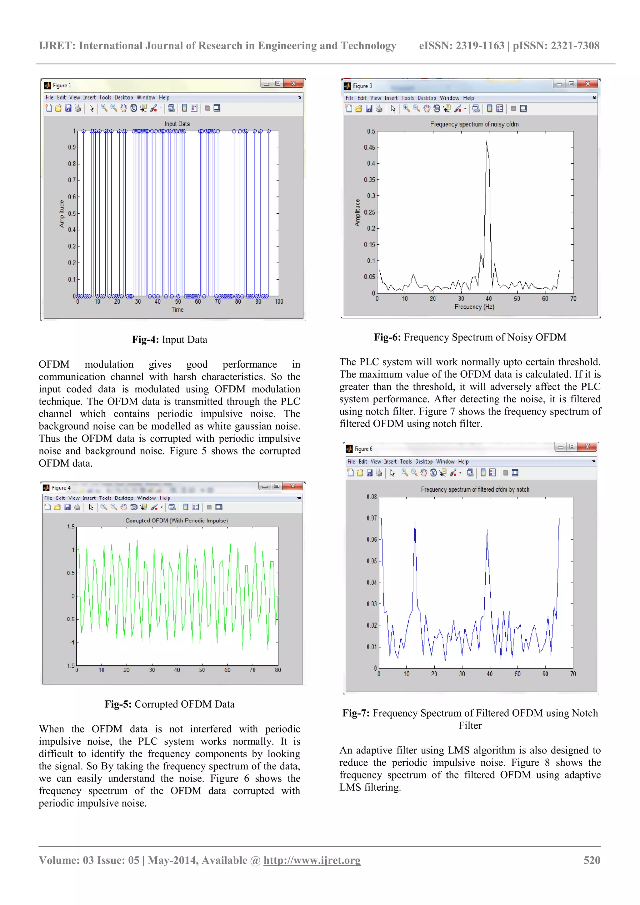
The received signal consists of signal, background noise and
impulsive noise. Signal is transmitted data from the
transmitter, background noise can be modelled as white
Gaussian noise (WGN), and the periodic impulsive noise is
the dominant impulsive noise. The periodic impulsive noise
is interfered with the transmitted signal and causes the
performance of the PLC system [5]. This system is a simple
and effective method to remove this periodic impulsive
noise in the frequency domain. By mitigating the impulsive
noise, the system performance improves.
First step is to detect the presence of noise. The periodic
impulsive noise interfered in N symbols are almost the
same, because the periodic impulsive noises remain
stationary over periods of seconds, minutes or even hours.
The OFDM signals are sent to the detection algorithm to
detect the presence of noise. The OFDM signals are
converted into frequency domain using FFT. These signals
are given to the noise detection algorithm. A threshold value
[6] is set and maximum values of the signals are calculated.
If the maximum value is greater than threshold value, then
the presence of periodic impulsive noise is confirmed.
Otherwise we can confirm that the noise is not interfered
with the signal. After detecting the presence of noise, the
next step is to design an adaptive notch filter. Notch filter is
also called as narrow band reject filter. It is commonly used
for the rejection of single frequency such as 60 Hz power
line hum. Notch filter plays an important role in
communications for eliminating undesired frequencies. An
adaptive notch filter is designed to suppress the periodic
impulsive noise. If the periodic impulsive noise is detected,
the notch filter, filtered the frequencies above a particular
threshold value, otherwise it is bypassed. It is an effective
method to filter the periodic impulsive noise from the power
line communication.
4. ADAPTIVE LMS FILTERING
Adaptive filters are filters whose tap weight vectors vary
with time. The principles of adaptive filter are also known as
adaptive noise canceller (ANC).In this filter reference signal
is adaptively filtered and it is subtracted with input signal
produces the estimated signal. The OFDM transmitted
signals are interfered with periodic impulsive noise when
signals are transmitted through the power line cables. These
corrupted signals can be recovered by using the adaptive
filtering using Least Mean Square (LMS) algorithm[7].
Figure 2 shows the adaptive noise cancellation system. By
using adaptive filtering the BER of PLC system reduces and
thus system performance improves.](https://image.slidesharecdn.com/periodicimpulsivenoisereductioninofdmbasedpowerlinecommunication-140819063010-phpapp01/75/Periodic-impulsive-noise-reduction-in-ofdm-based-power-line-communication-2-2048.jpg)
![IJRET: International Journal of Research in Engineering and Technology eISSN: 2319-1163 | pISSN: 2321-7308
_______________________________________________________________________________________________
Volume: 03 Issue: 05 | May-2014, Available @ http://www.ijret.org 519
Fig-2: Adaptive Noise Cancellation System
Adaptive filters are self learning filters which do not require
any prior knowledge about the input signal. Adaptive noise
cancellation system consists of two inputs such as primary
input signal d(n) and reference input signal x(n). The desired
transmitted signal d(n) corrupted with periodic impulsive
noise and x(n) is the reference signal which is the undesired
noise must be filtered out of the system. The adaptive filter
using LMS algorithm filtered the undesired noise and
produce the uncorrupted signal.
e(n) = s(n) + x1(n)- y(n)------(1)
Then the output y(n) is subtracted from the primary input to
produce the system output e(n).
4.1 LMS Algorithm
Adaptive filter using LMS algorithm is used for cancelling
the noise which is interfered with transmitted OFDM signal.
The algorithm is as follows:-
1) Initialize the algorithm by setting all filter
coefficients to zero.
2) Estimation error is calculated by subtracting the
desired signal d(n) with filtered signal y(n)
e(n) = d(n) - y(n)-------------------------(2)
3) Updated estimate is the summation of old estimate
and product of adaptation costant ,estimation error
and tap input.
wi(n+1) = wi(n) + mu*e(n)*u(n-i)-----(3)
4) (4) constitutes the filteration process.
y(n)= wi(n)*u(n-i)----------------------(4)
5) Increment the iteration number N by one, go to back
to step 2, and repeat the computation. Figure 3 shows
the flow chart of adaptive filter using LMS
algorithm.
Fig-3: Flowchart of Adaptive LMS Algorithm
5. SIMULATION RESULTS
Simulation is done in MATLAB. The input bit stream is
randomly generated at the transmitted end. Error detection
and correction techniques are essential for reliable
communication over noisy channel [8]. Convolution coding
is used for coding the input bit stream. Convolution codes
are one of the powerful and efficient error correcting codes
for detecting and correcting burst errors. Figure 4 shows the
randomly generated input data.](https://image.slidesharecdn.com/periodicimpulsivenoisereductioninofdmbasedpowerlinecommunication-140819063010-phpapp01/75/Periodic-impulsive-noise-reduction-in-ofdm-based-power-line-communication-3-2048.jpg)
![IJRET: International Journal of Research in Engineering and Technology eISSN: 2319-1163 | pISSN: 2321-7308
_______________________________________________________________________________________________
Volume: 03 Issue: 05 | May-2014, Available @ http://www.ijret.org 522
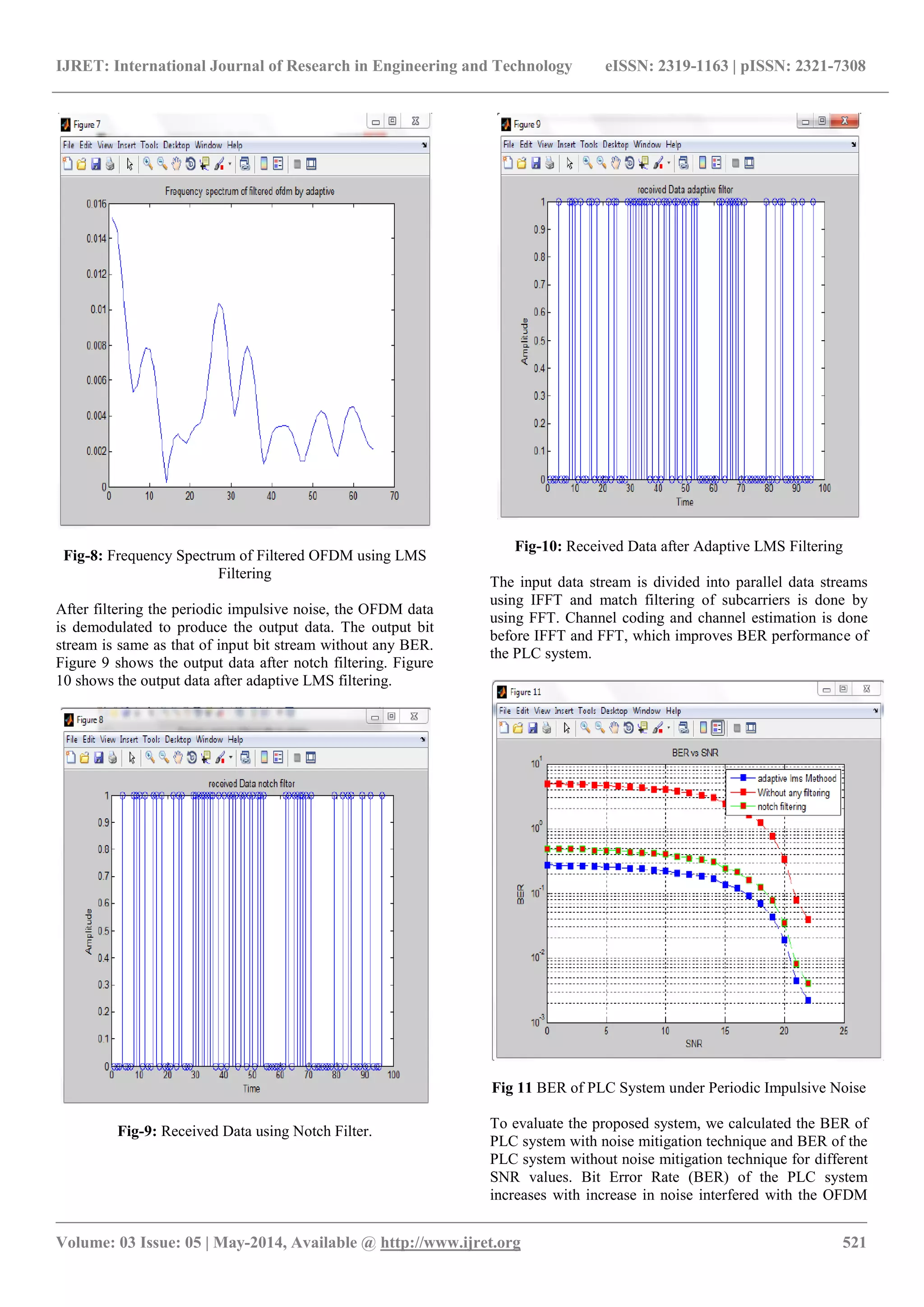
data. The bit error rate (BER) is the percentage of bits that
have errors relative to the total number of bits received.
Fig 11 shows the BER of the PLC system under periodic
impulsive noise. Red colour represents without any filtering,
light green colour represents with filtering using notch filter
and blue colour represents with filtering using adaptive
LMS filtering . Simulation results shows that BER rate of
the PLC system with noise mitigation technique is decreased
than BER of the PLC system without noise mitigation
algorithm. BER of PLC system using adaptive LMS filtering
is decreased than BER of PLC system using notch filter.
Thus these filtering techniques can be used to mitigate the
periodic impulsive noise from the power line
communication system. The proposed algorithm is a simple
and effective method for mitigating periodic impulsive noise
from the power line communication channel and thus it
improves the performance of the PLC system
6. CONCLUSIONS
The main objective of the paper is to reduce the effect of
periodic impulsive noise in the Power Line Communication
channel. First the presence of periodic impulsive noise is
detected and then an adaptive notch filter is designed to
mitigate the impulsive noise which is interfered with the
OFDM data. Then an adaptive LMS filter is designed and
suppress the noise. Simulation results shows that proposed
algorithm gives better performance than conventional PLC
system. i.e, BER of PLC system with filtering is decreased
than BER of PLC system without filtering. Adaptive LMS
algorithm can be used for effectively remove the periodic
impulsive noise.
ACKNOWLEDGEMENTS
I would like to thank all faculty members of ECE
department, Nehru College of Engineering and Research
Centre, Thrissur, Kerala for the guidance and support
throughout the project work.
REFERENCES
[1]. M. Zimmermann and K. Dosert, “Analysis and
modelling of impulsive noise in broadband power line
communications, “IEEE Trans. Electromagn.Compat., Vol
44,pp 249-258,February 2002.
[2]. G.Ndo, P.Sihon, and M.H Hamon, “Adaptive noise
mitigation in impulsive environment : Application to power
line communication,”IEEE Transactions on Power Delivery.
Vol 25, pp647-656,April 2010.
[3]. A.Mengi, A.J Han Vink, ”Successive impulsive noise
suppression in OFDM” in Proc. IEEE.ISPLC, pp 33-37
March 2010.
[4]. H.Meng, Y.L.Guan and S.Chen, Modelling and analysis
of noise effects on broadband power line communications,
IEEE Transactions on Power Delivery, pp 14-21,April 2006.
[5]. Gaofeng Ren, Shushan Qiao, Huidong Zhao,
Chundyang Li and Yong Hei, “Mitigation of periodic
impulsive noise in OFDM based power line
communications, IEEE Transactions on Power Delivery,
Vol 28,825-834,April 2013.
[6]. Y.C.Kim, J.Y.Kim,” Novel noise reduction scheme for
power line communication systems with smart grid
applications” in Proc. IEEE.ICCE, pp 791-792, Jan 2011
[7]. Ondraka J, Oravec R, K adlec J, Cochereova E, “
Simulation Of RLS And LMS Algorithm For Adaptive
Noise Cancellation In MATLAB”, Department Of
Radioelectronics, Bratislava, Slovak Republic
[8]. Mario Bogdanovic, “Computer based simulation model
realization of OFDM communication over power lines”,
20th TELFOR, pp 249-252, Nov. 2012.
BIOGRAPHIES
Sumi Mathew was born in Kerala, India, in 1990. She
received the B.Tech degree in electronics
and communication Engineering from
CUSAT university, India, in 2012 and is
currently pursuing M.Tech degree in
applied electronics and communication
system at Nehru College of Engineering
and Research Centre, Kerala, India. Her
research interests include power line communication,
modulation techniques, and wireless communication.
Prasanth Murukan received B.Tech Degree in electronics
and communication engineering from University of Kerala,
India in 2008 and M.E degree in applied electronics from
Sardar Raja College Of Engineering, Tirunelveli,
Tamilnadu, India in 2012. Currently, he is professor in
electronics and communication system at Nehru College of
Engineering and Research Centre, Thrissur, Kerala, India.](https://image.slidesharecdn.com/periodicimpulsivenoisereductioninofdmbasedpowerlinecommunication-140819063010-phpapp01/75/Periodic-impulsive-noise-reduction-in-ofdm-based-power-line-communication-6-2048.jpg)

This document presents a method for reducing periodic impulsive noise in OFDM-based power line communication systems. It uses an adaptive notch filter and adaptive LMS filter to detect and remove periodic impulsive noise from OFDM signals transmitted over power lines. Simulation results show that both filtering methods improve the bit error rate of the power line communication system compared to no filtering. The adaptive LMS filter provides better noise reduction and lower bit error rates than the adaptive notch filter alone. The proposed noise filtering approach improves the performance of OFDM power line communication systems operating in noisy power line environments.