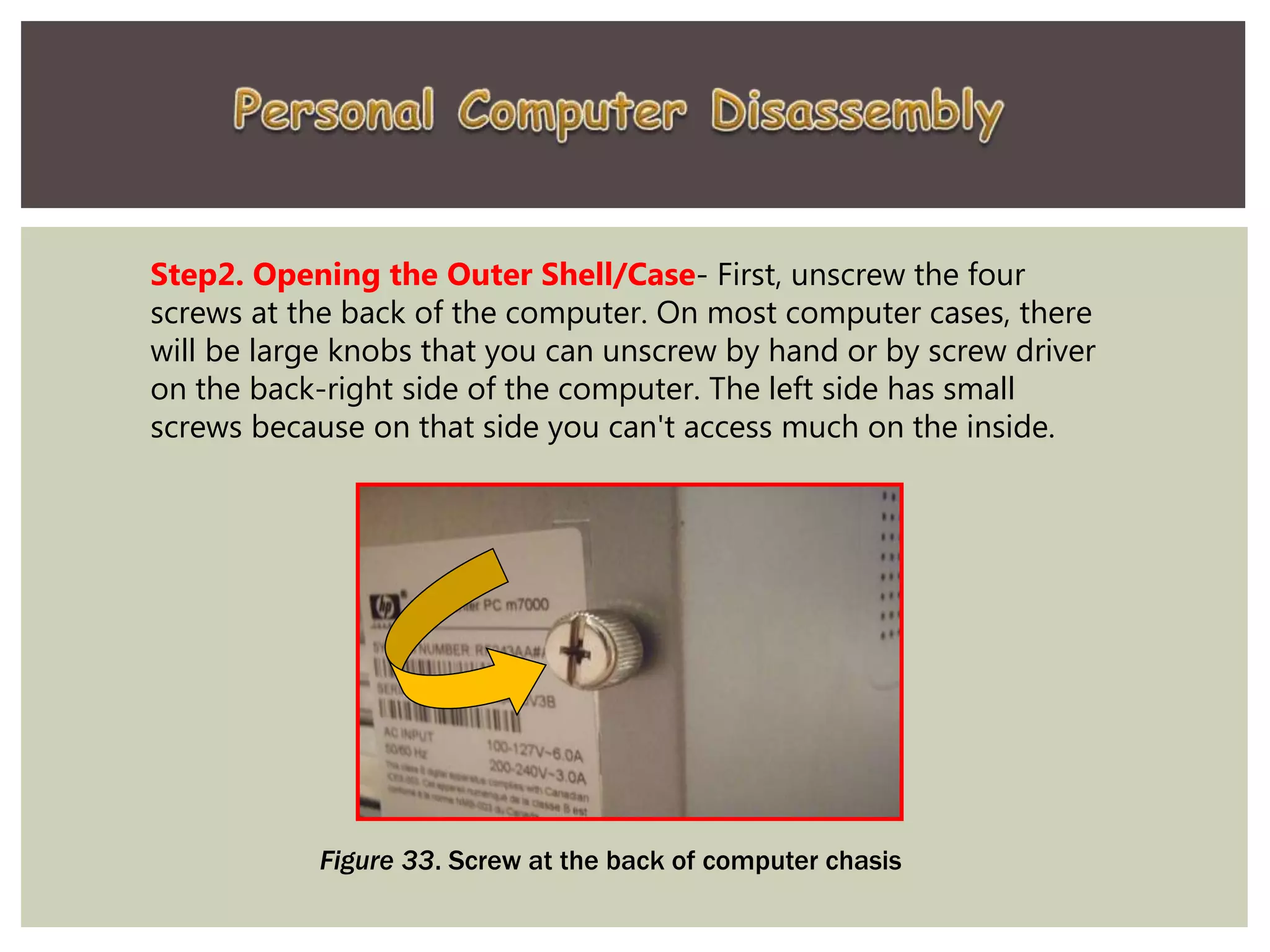
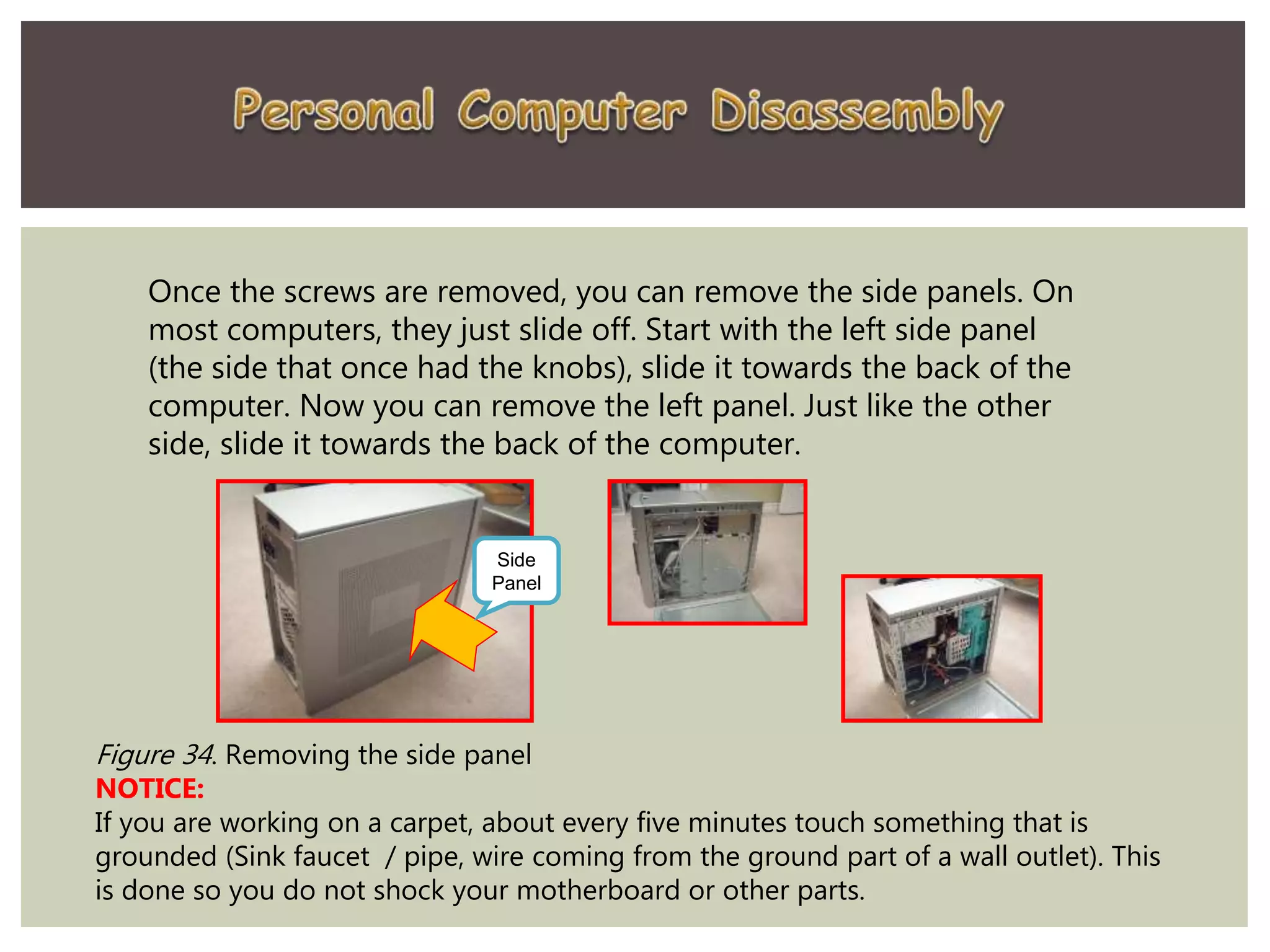
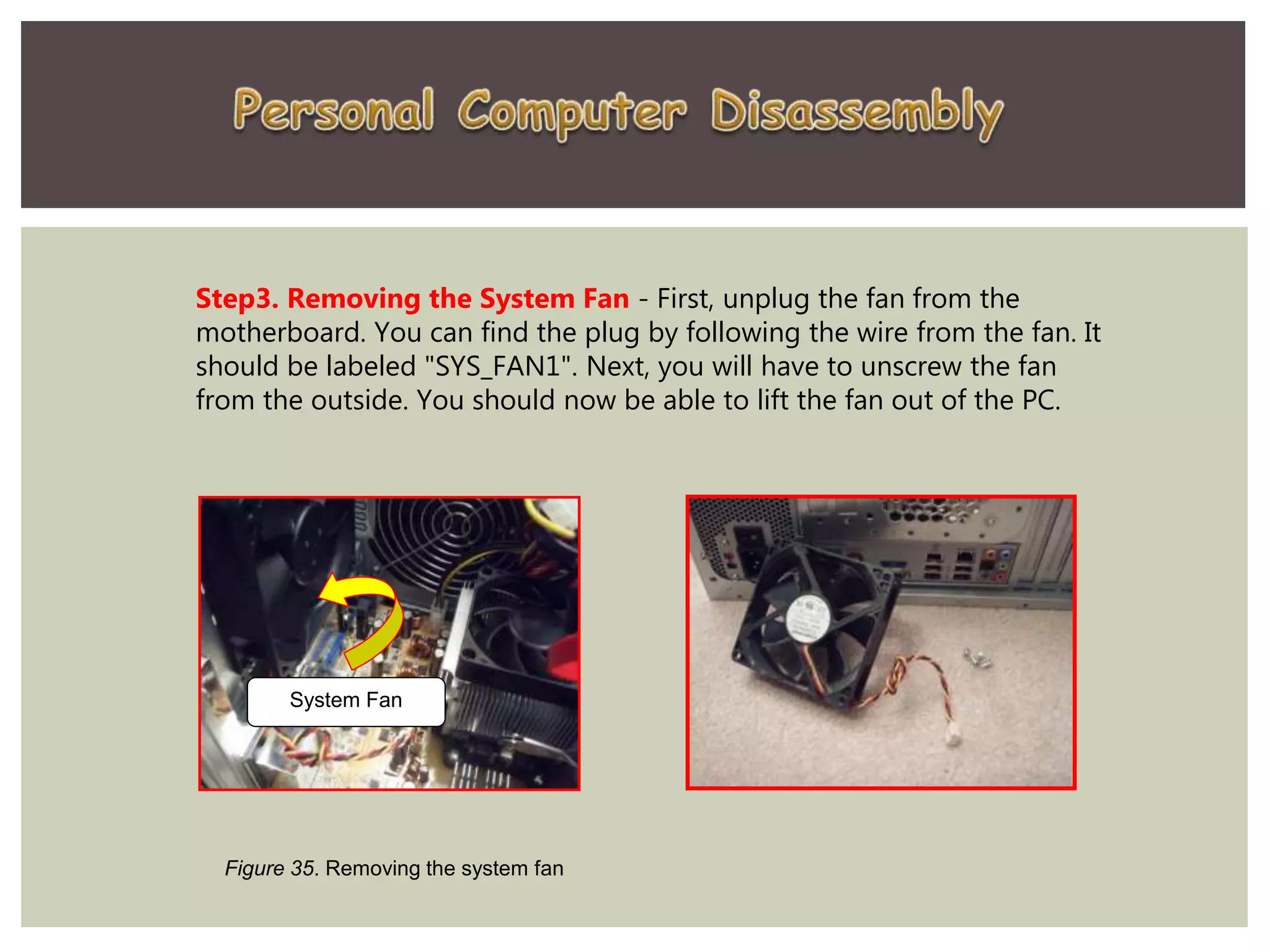
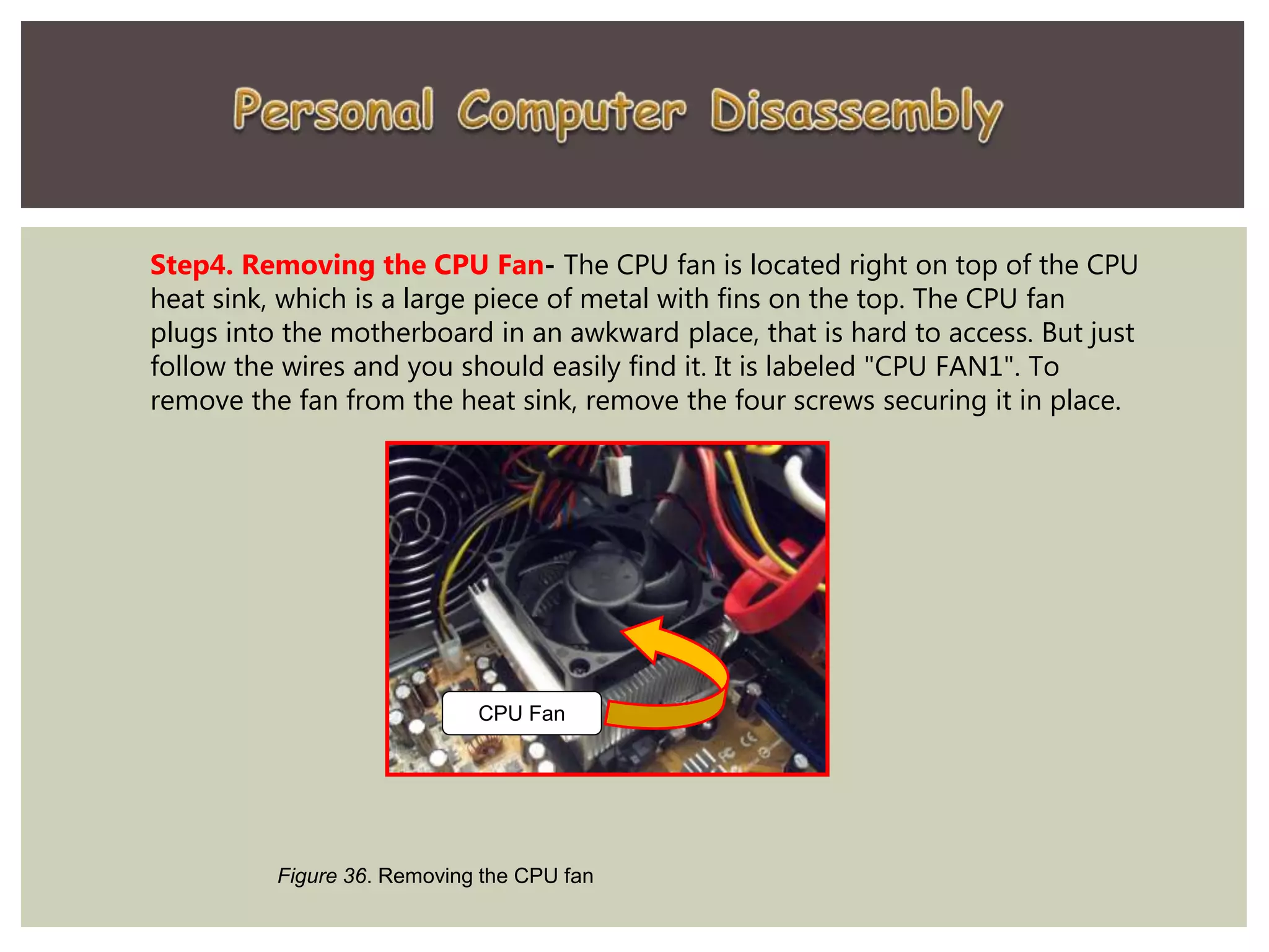
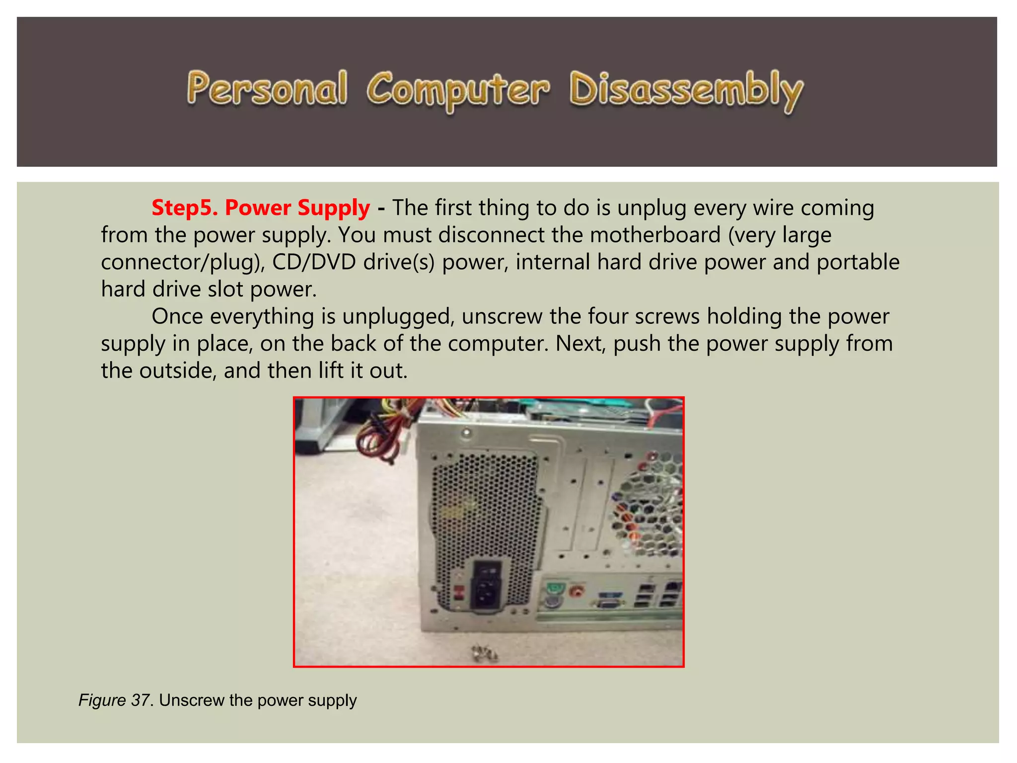
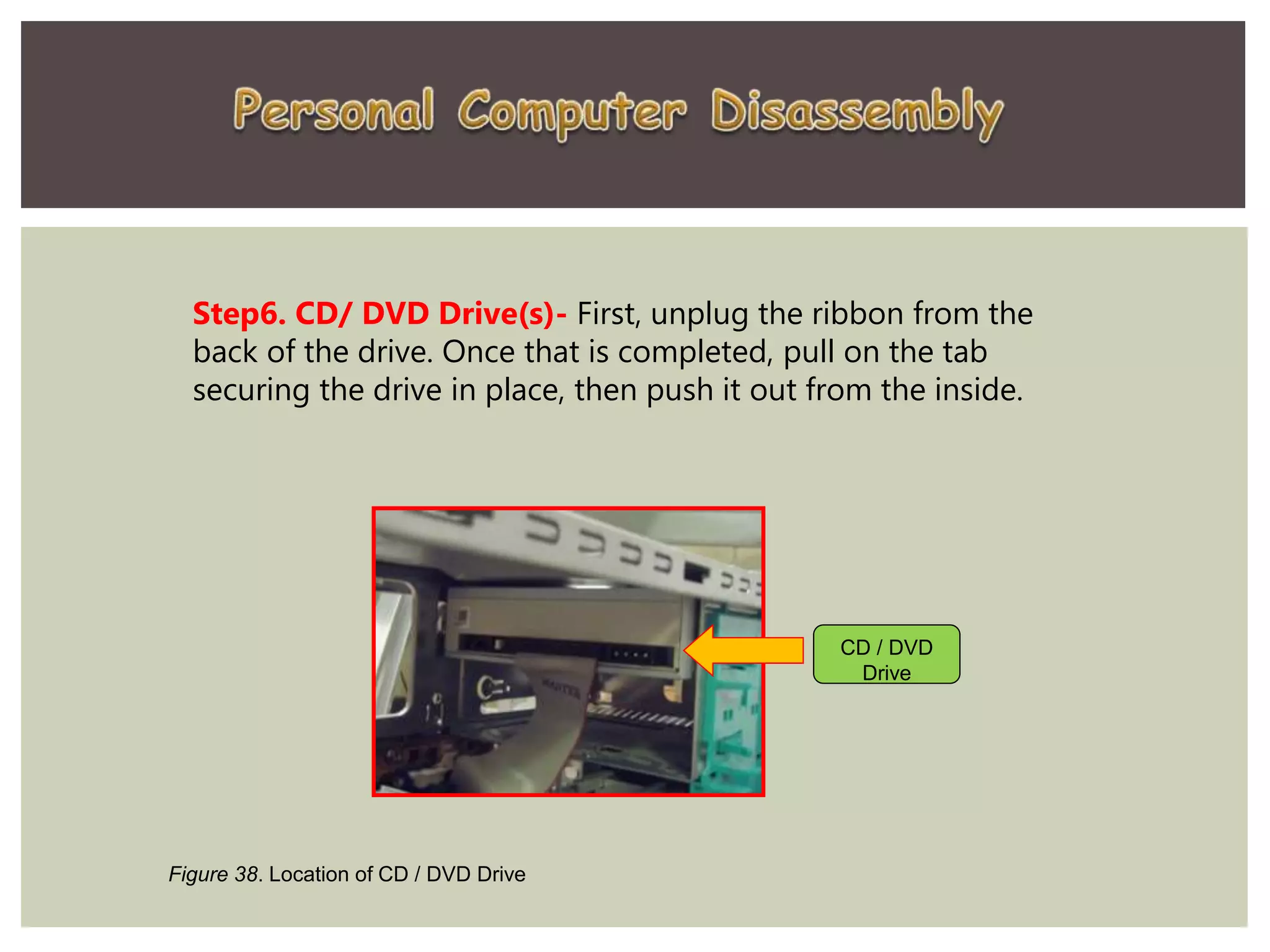
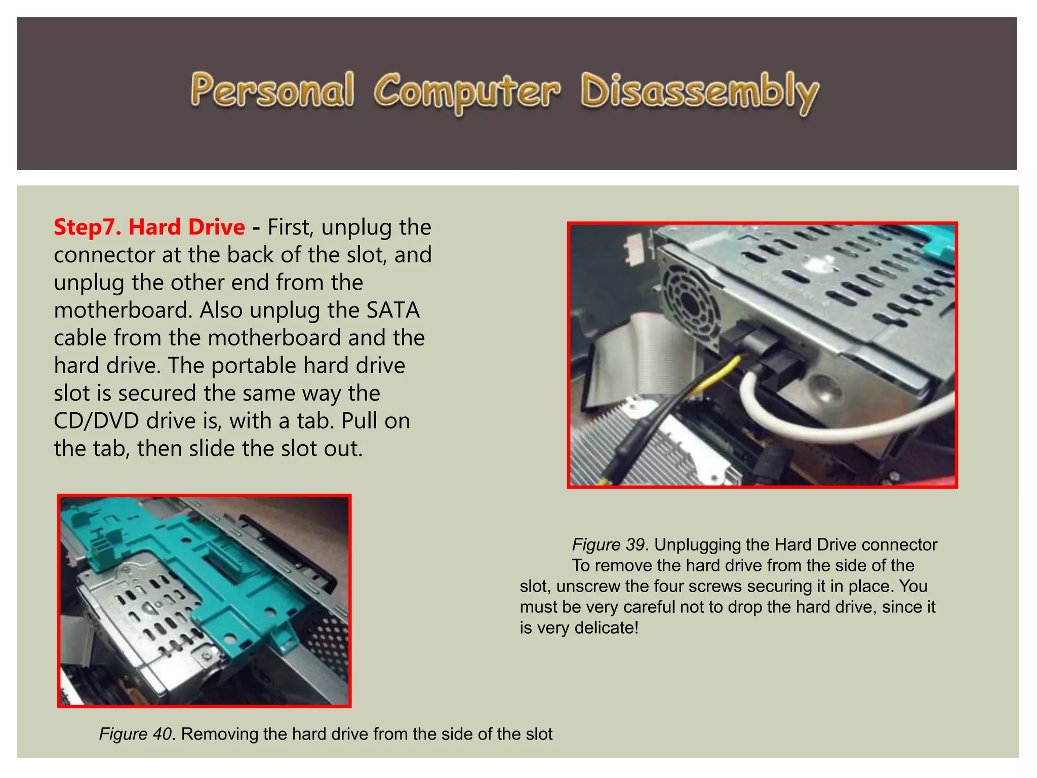
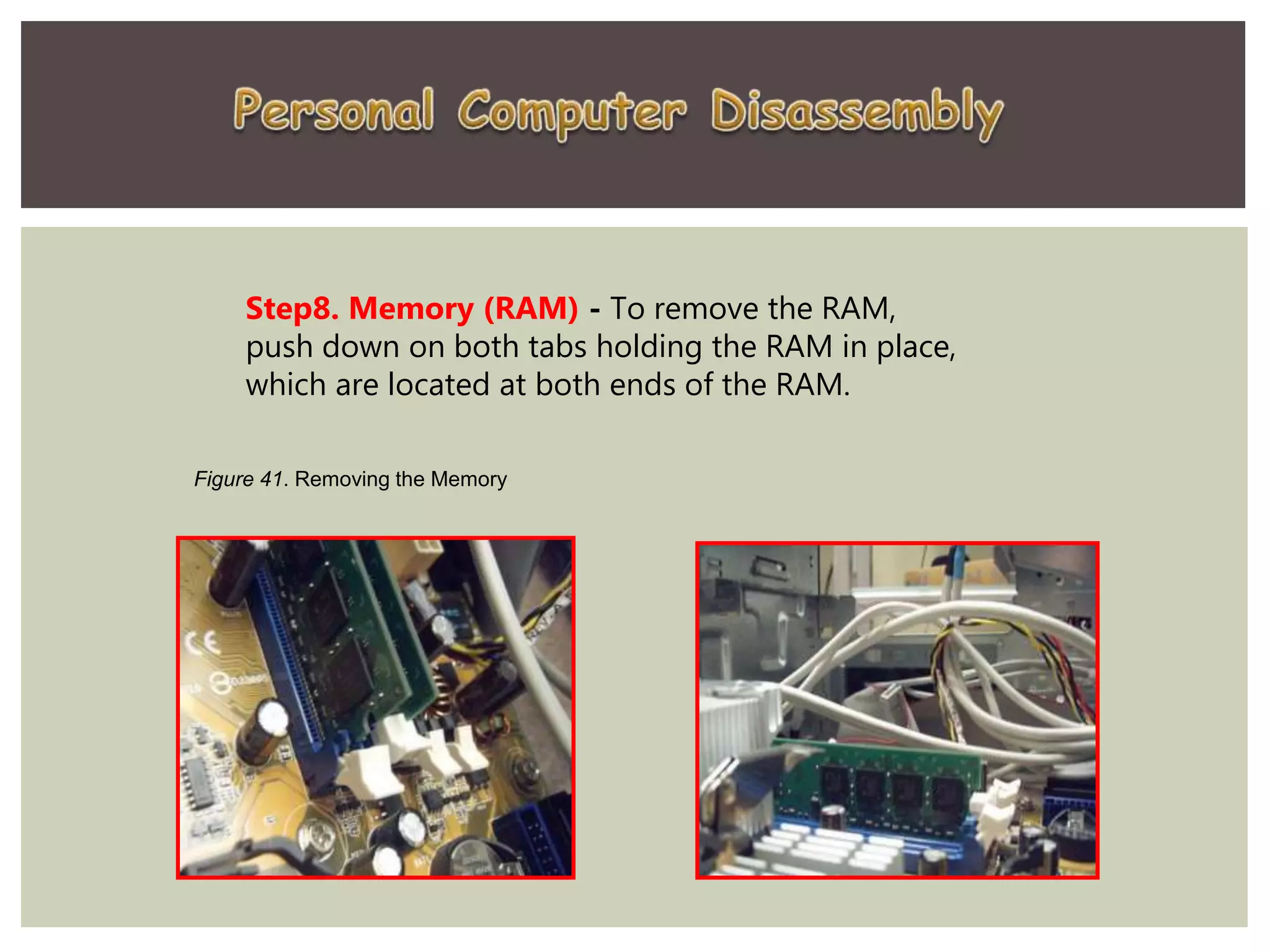
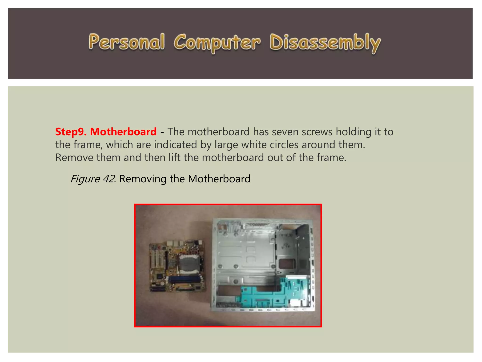
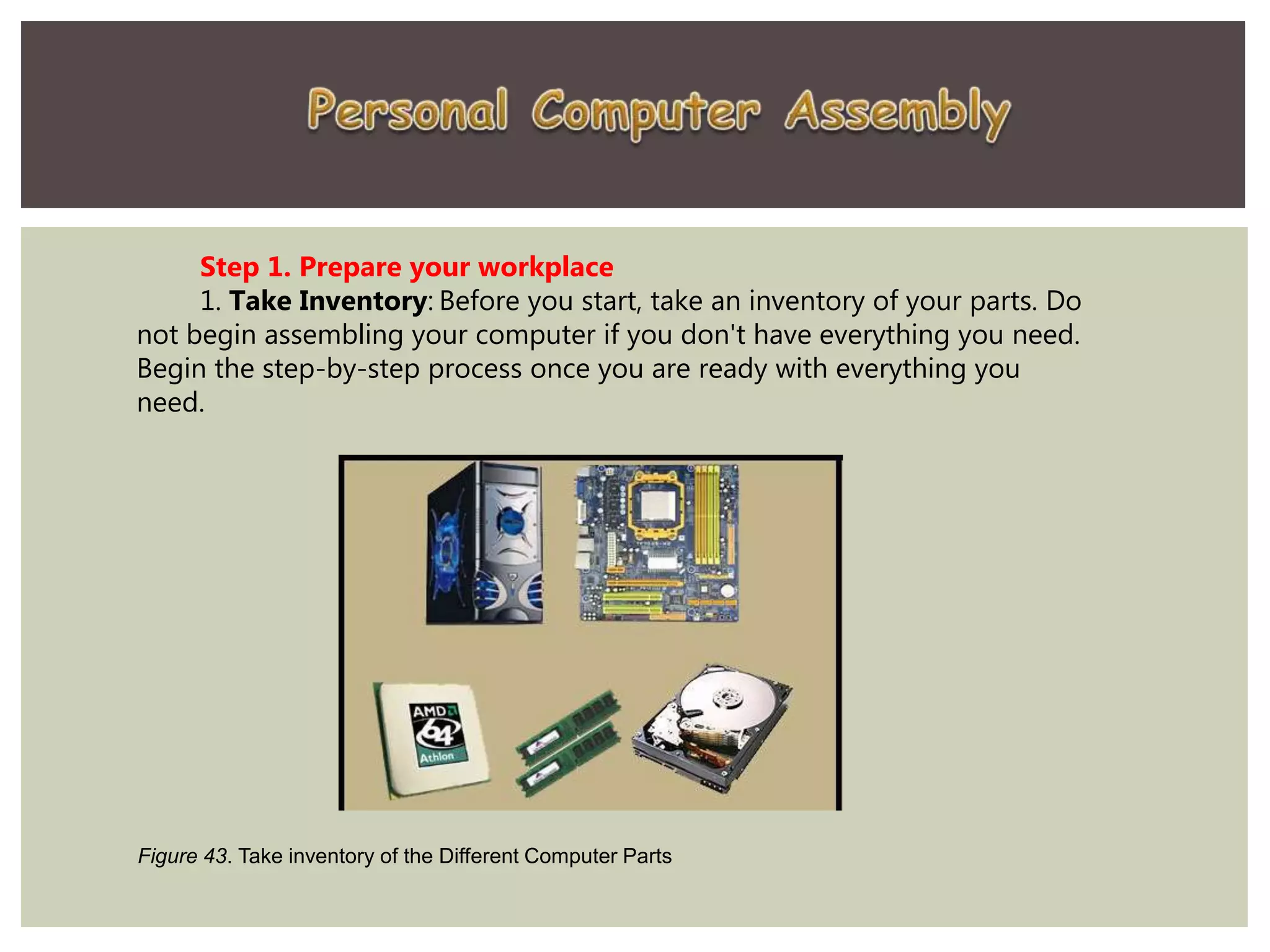
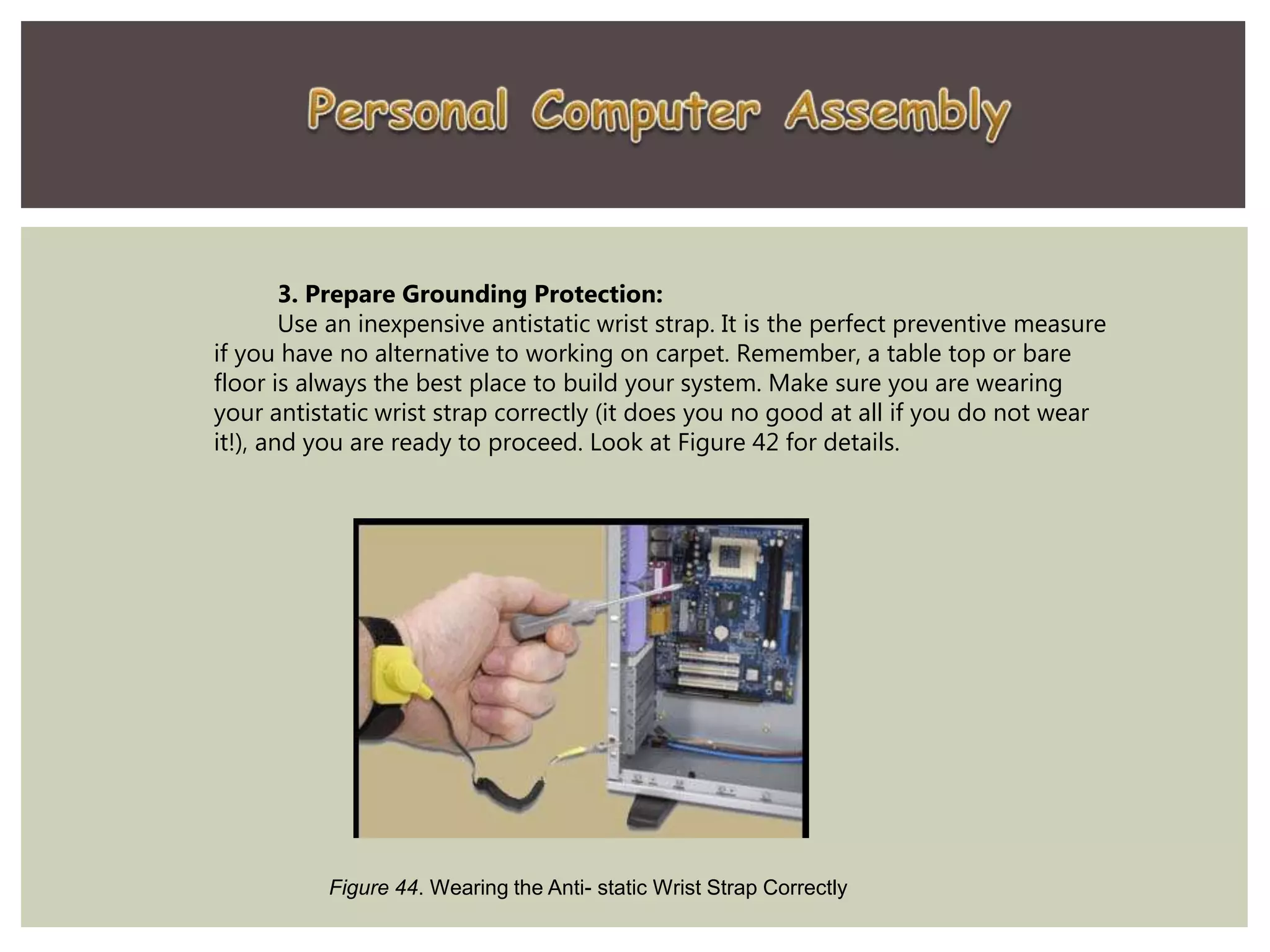
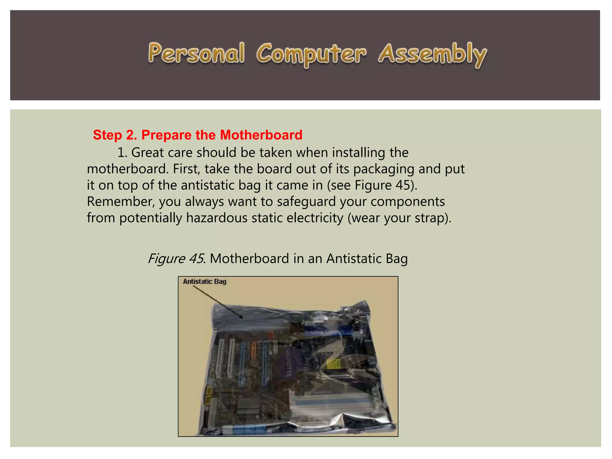
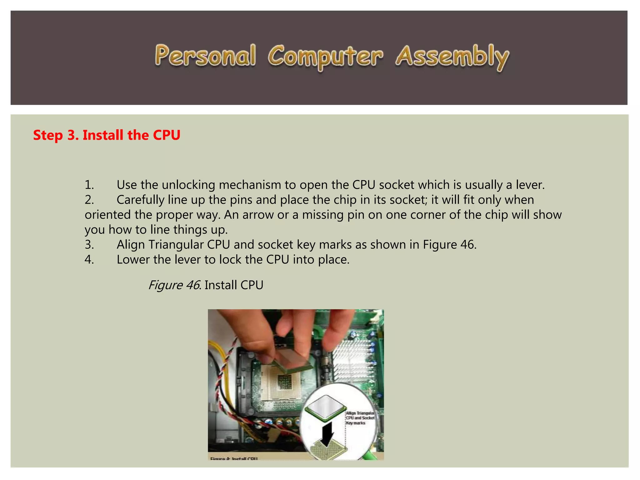
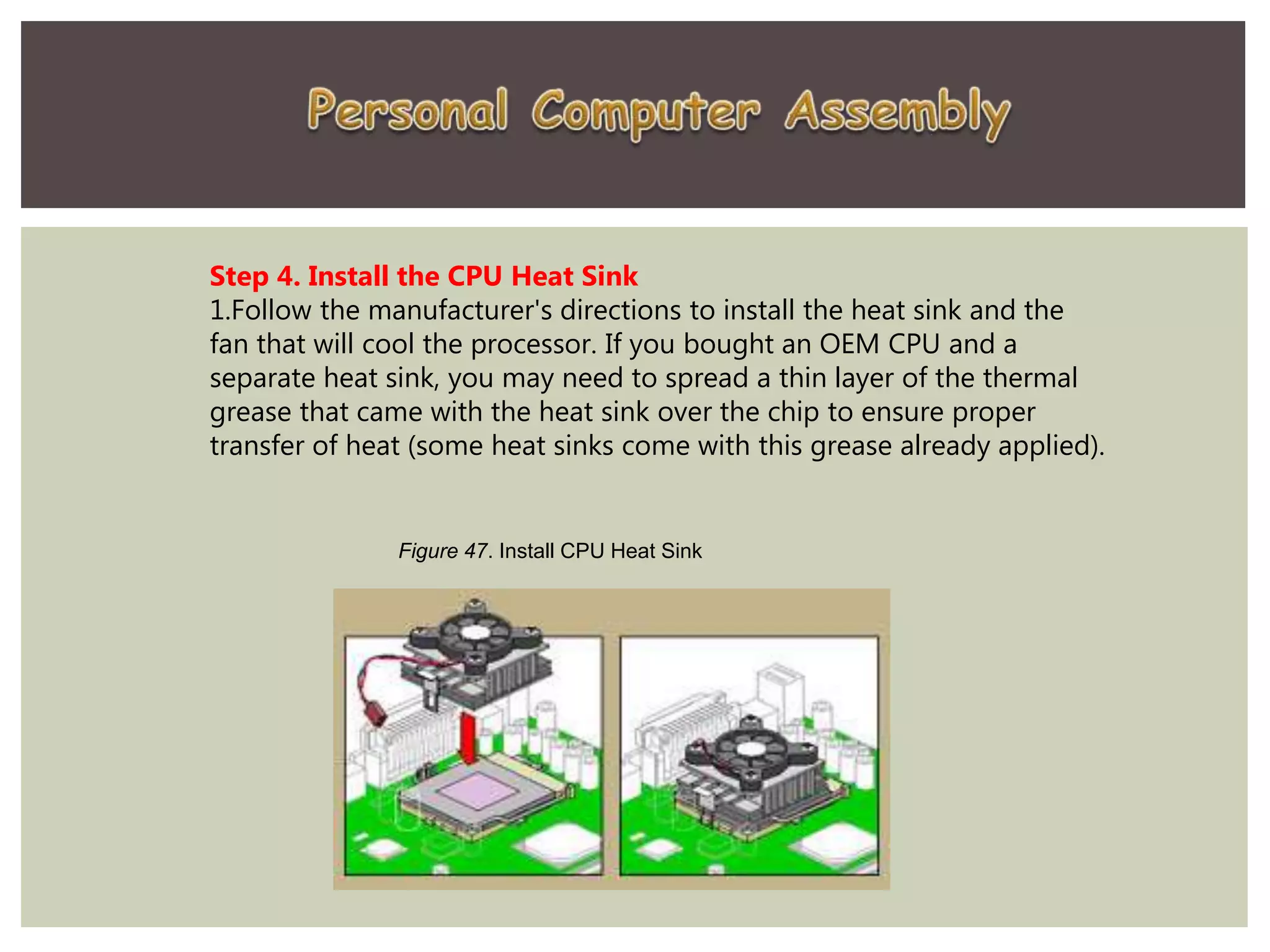
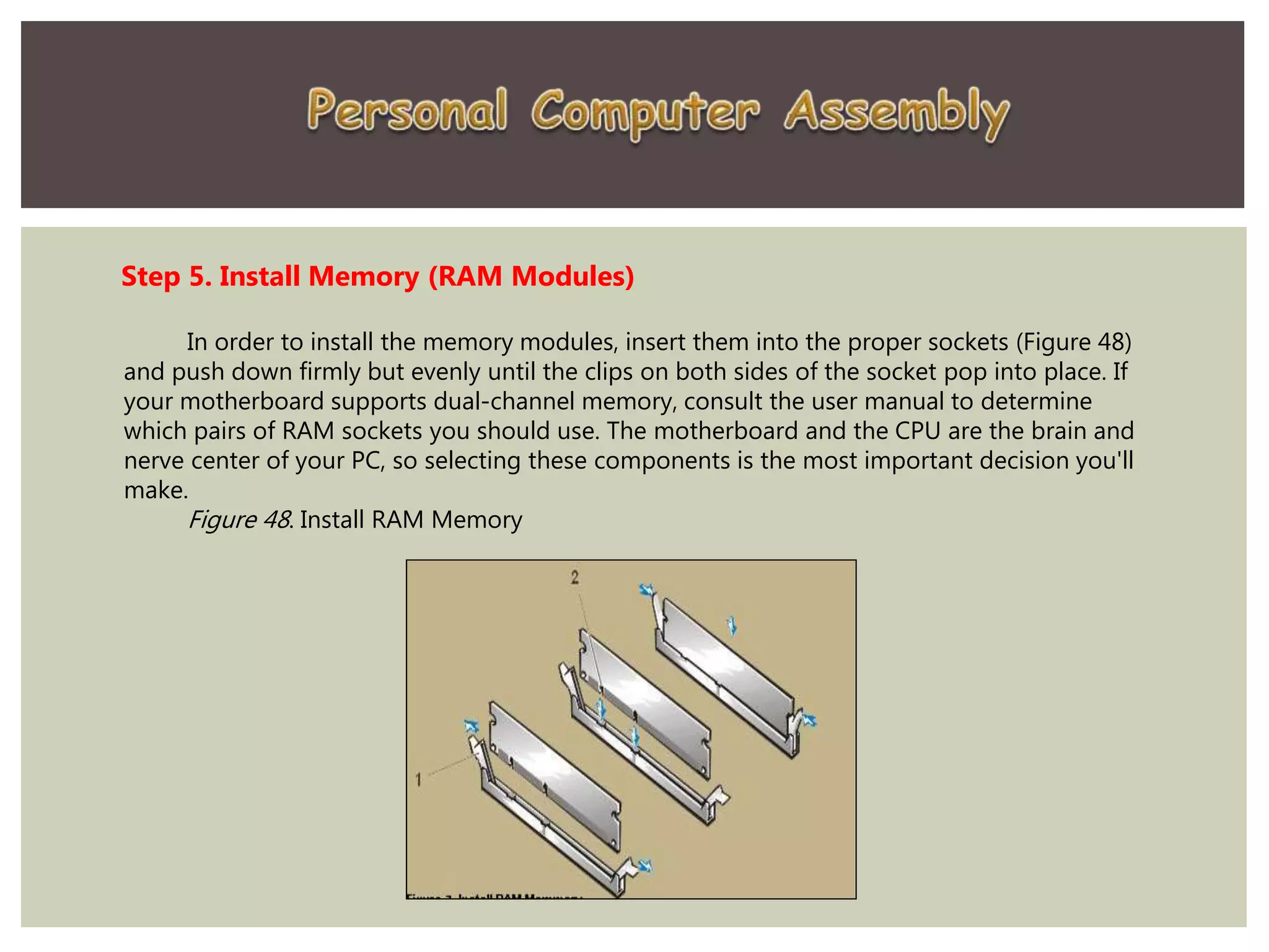
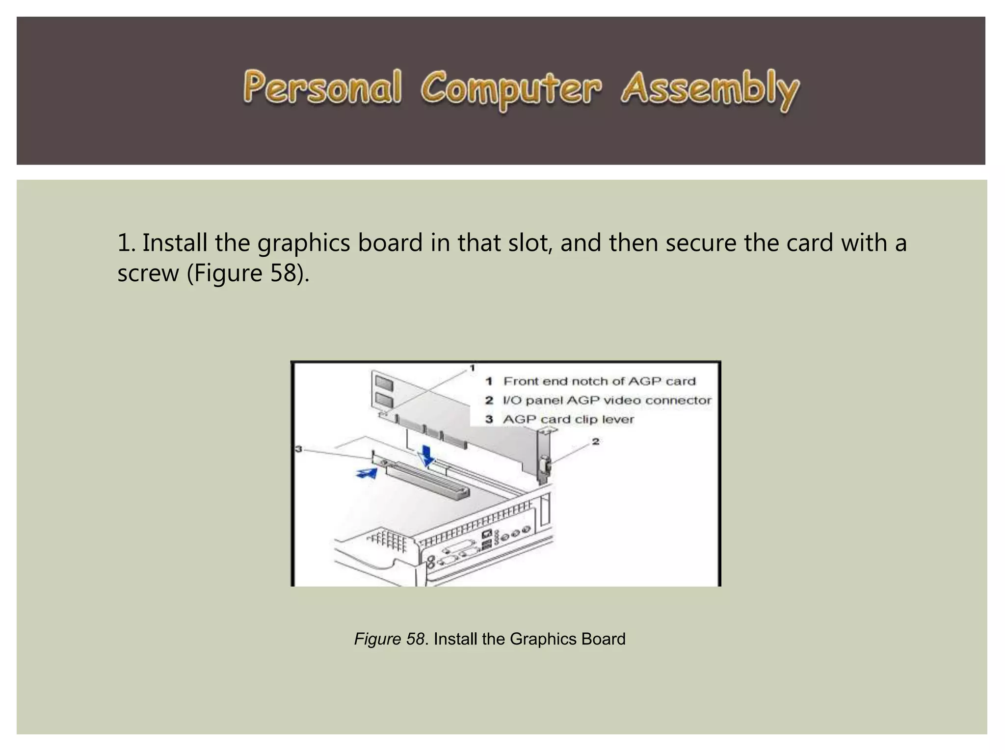
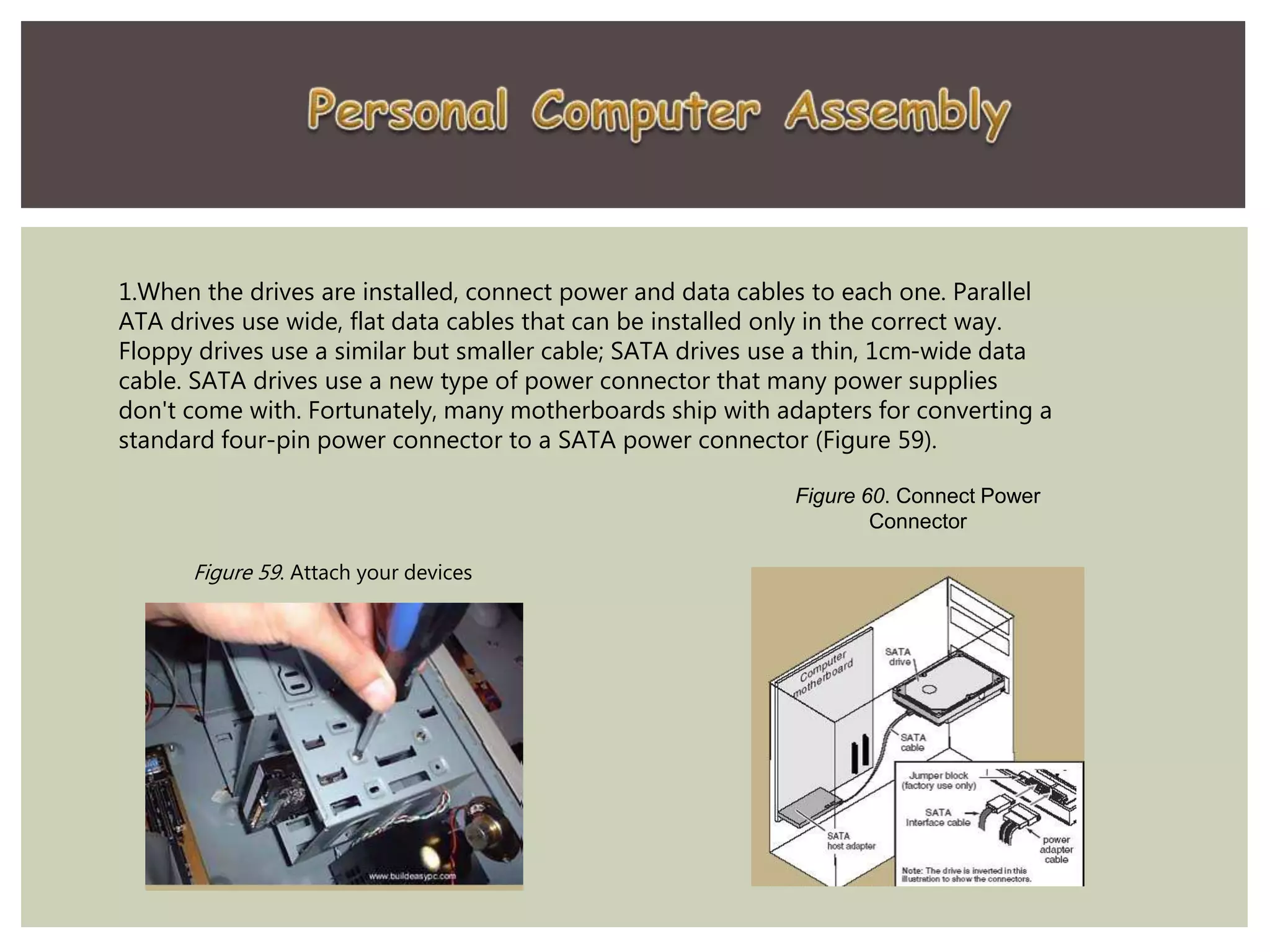
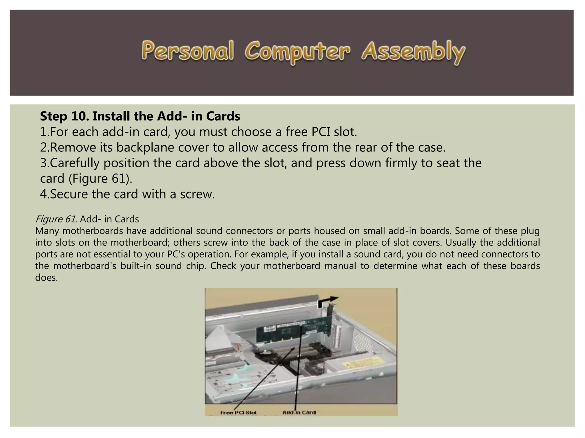
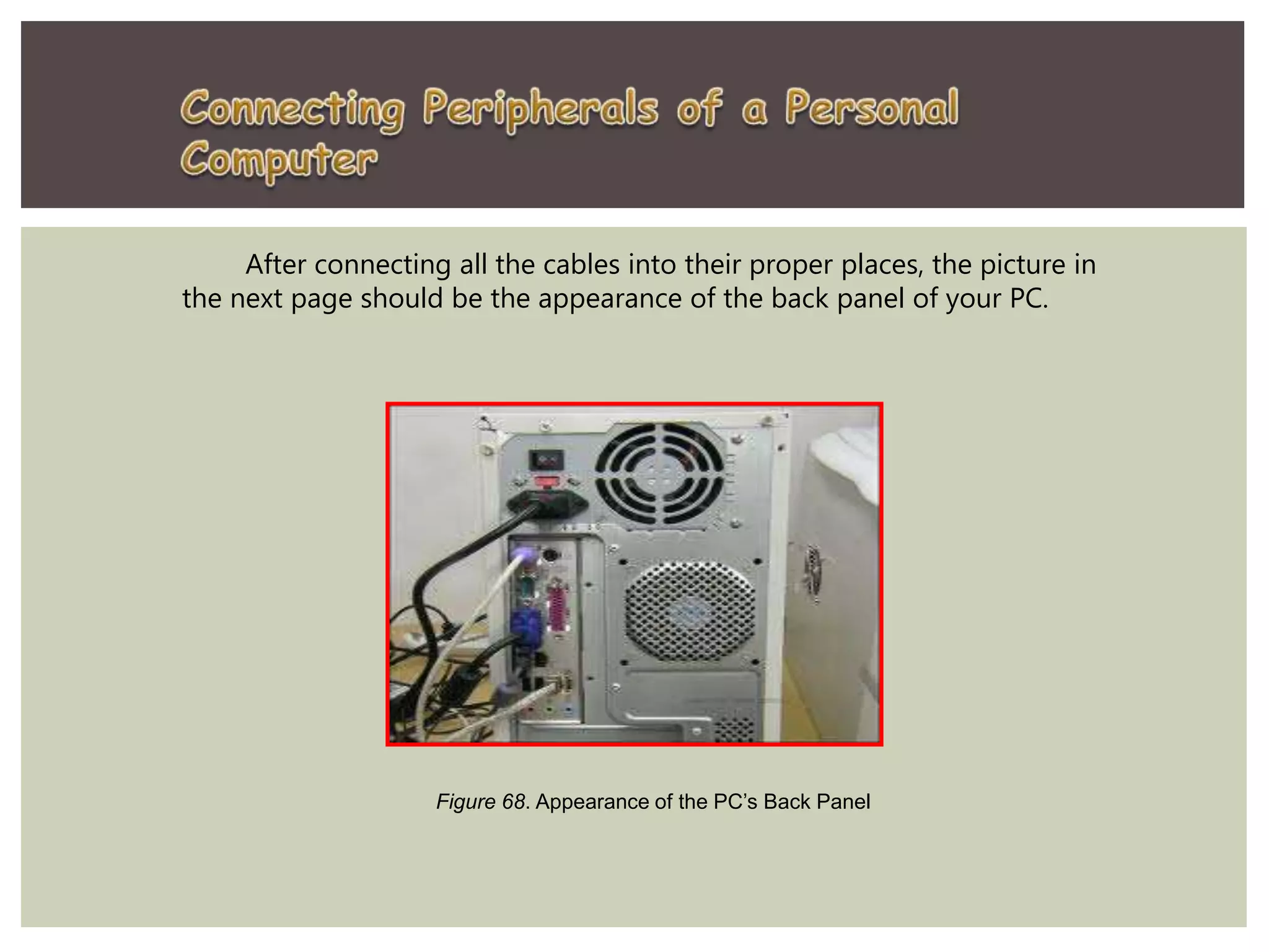
 Before starting computer disassembly, make sure you have
the tools you need and they're all close by and handy and
be sure to have a container to keep the screws in so you
have them when you want to put things back together.
Step1. Unplugging - The first thing you do is to unplug every cable
that is plugged in to your computer. That includes the cables such as
Power, USB, Mouse, Keyboard, Internet, Ethernet, Modem, AMFM
Antenna, Cable TV, etc. Just unplug all the cables for safety purposes.
Now that your computer is fully unplugged, move your PC to a
clean work space, preferably a carpet. The carpet is better than tile,
because screws and other small parts will roll around.
Step2. Opening the Outer Shell/Case- First, unscrew the four
screws at the back of the computer. On most computer cases, there
will be large knobs that you can unscrew by hand or by screw driver
on the back-right side of the computer. The left side has small
screws because on that side you can't access much on the inside.
Figure 33. Screw at the back of computer chasis
Once the screws are removed, you can remove the side panels. On
most computers, they just slide off. Start with the left side panel
(the side that once had the knobs), slide it towards the back of the
computer. Now you can remove the left panel. Just like the other
side, slide it towards the back of the computer.
Side
Panel
Figure 34. Removing the side panel
NOTICE:
If you are working on a carpet, about every five minutes touch something that is
grounded (Sink faucet / pipe, wire coming from the ground part of a wall outlet). This
is done so you do not shock your motherboard or other parts.
System Fan
Step3. Removing the System Fan - First, unplug the fan from the
motherboard. You can find the plug by following the wire from the fan. It
should be labeled "SYS_FAN1". Next, you will have to unscrew the fan
from the outside. You should now be able to lift the fan out of the PC.
Figure 35. Removing the system fan
Step4. Removing the CPU Fan- The CPU fan is located right on top of the CPU
heat sink, which is a large piece of metal with fins on the top. The CPU fan
plugs into the motherboard in an awkward place, that is hard to access. But just
follow the wires and you should easily find it. It is labeled "CPU FAN1". To
remove the fan from the heat sink, remove the four screws securing it in place.
CPU Fan
Figure 36. Removing the CPU fan
Step5. Power Supply - The first thing to do is unplug every wire coming
from the power supply. You must disconnect the motherboard (very large
connector/plug), CD/DVD drive(s) power, internal hard drive power and portable
hard drive slot power.
Once everything is unplugged, unscrew the four screws holding the power
supply in place, on the back of the computer. Next, push the power supply from
the outside, and then lift it out.
Figure 37. Unscrew the power supply
Step6. CD/ DVD Drive(s)- First, unplug the ribbon from the
back of the drive. Once that is completed, pull on the tab
securing the drive in place, then push it out from the inside.
CD / DVD
Drive
Figure 38. Location of CD / DVD Drive
Step7. Hard Drive - First, unplug the
connector at the back of the slot, and
unplug the other end from the
motherboard. Also unplug the SATA
cable from the motherboard and the
hard drive. The portable hard drive
slot is secured the same way the
CD/DVD drive is, with a tab. Pull on
the tab, then slide the slot out.
Figure 39. Unplugging the Hard Drive connector
To remove the hard drive from the side of the
slot, unscrew the four screws securing it in place. You
must be very careful not to drop the hard drive, since it
is very delicate!
Figure 40. Removing the hard drive from the side of the slot
Figure 41. Removing the Memory
Step8. Memory (RAM) - To remove the RAM,
push down on both tabs holding the RAM in place,
which are located at both ends of the RAM.
Step9. Motherboard - The motherboard has seven screws holding it to
the frame, which are indicated by large white circles around them.
Remove them and then lift the motherboard out of the frame.
Figure 42. Removing the Motherboard
Step 1. Prepare your workplace
1. Take Inventory: Before you start, take an inventory of your parts. Do
not begin assembling your computer if you don't have everything you need.
Begin the step-by-step process once you are ready with everything you
need.
Figure 43. Take inventory of the Different Computer Parts
2. Make Space, Make Time:
Building a PC takes up space - about a dining room
table worth. So make sure you have plenty of working
room and a few hours to proceed with minimal
interruption. Work on a flat, stable table top surface, or
bare floor, where you have room to layout all of the
items.
3. Prepare Grounding Protection:
Use an inexpensive antistatic wrist strap. It is the perfect preventive measure
if you have no alternative to working on carpet. Remember, a table top or bare
floor is always the best place to build your system. Make sure you are wearing
your antistatic wrist strap correctly (it does you no good at all if you do not wear
it!), and you are ready to proceed. Look at Figure 42 for details.
Figure 44. Wearing the Anti- static Wrist Strap Correctly
4. Have the Drivers Ready:
Assuming you have another internet connected PC,
download the latest drivers from the vendors' websites
for each component you will be installing. Sometimes
drivers are updated between the time the component was
manufactured and the time you are installing it. It is
always best to have the latest. Copy them to a CD for
easy access.
Step 2. Prepare the Motherboard
1. Great care should be taken when installing the
motherboard. First, take the board out of its packaging and put
it on top of the antistatic bag it came in (see Figure 45).
Remember, you always want to safeguard your components
from potentially hazardous static electricity (wear your strap).
Figure 45. Motherboard in an Antistatic Bag
1. Before you secure the motherboard onto the PC
case/chassis, inspect it carefully for any visible defects.
2. Next, review the motherboard manual, to make sure you
are familiar with the motherboard layout and understand
which socket is which. Manuals are extremely helpful,
usually easy to read, and include illustrations. Below you
can find instructions on how to install the processor, the
heat sink and the memory modules on the motherboard.
You should not place the motherboard in the computer
case until you are told to do so.
Step 3. Install the CPU
1. Use the unlocking mechanism to open the CPU socket which is usually a lever.
2. Carefully line up the pins and place the chip in its socket; it will fit only when
oriented the proper way. An arrow or a missing pin on one corner of the chip will show
you how to line things up.
3. Align Triangular CPU and socket key marks as shown in Figure 46.
4. Lower the lever to lock the CPU into place.
Figure 46. Install CPU
Step 4. Install the CPU Heat Sink
1.Follow the manufacturer's directions to install the heat sink and the
fan that will cool the processor. If you bought an OEM CPU and a
separate heat sink, you may need to spread a thin layer of the thermal
grease that came with the heat sink over the chip to ensure proper
transfer of heat (some heat sinks come with this grease already applied).
Figure 47. Install CPU Heat Sink
2. Attach the clip that holds the heat sink in place
keeping in mind that it may require a fair amount of
force. Again, follow the instructions that came with
the heat sink.
3. They will show you how to fit it correctly. If you are
in doubt, you can visit the manufacturer's website for
more information.
Plug the CPU fan's power connector into the proper
connector on the motherboard.
Step 5. Install Memory (RAM Modules)
In order to install the memory modules, insert them into the proper sockets (Figure 48)
and push down firmly but evenly until the clips on both sides of the socket pop into place. If
your motherboard supports dual-channel memory, consult the user manual to determine
which pairs of RAM sockets you should use. The motherboard and the CPU are the brain and
nerve center of your PC, so selecting these components is the most important decision you'll
make.
Figure 48. Install RAM Memory
Step 6. Place the motherboard into the case
1. Some PC cases have a removable motherboard tray. If
yours does, remove the screws holding it in place and
pull it out of the case (Figure 49).
Figure 49. Remove Motherboard Tray
2. Note the pattern of the holes in your motherboard (Figure 50), and screw
brass standoffs into the motherboard tray or into the PC case in the correct
locations (ALWAYS check the manual and follow their instructions to the
letter).
Figure 50. Screw Brass Standoffs Into the Motherboard
3. Check the layout of the sockets on the motherboard, and confirm
that the ports on your motherboard's back panel match the holes
on the case's Input/Output (I/O) shield that is installed in your case.
If necessary, remove the old I/O shield by tapping it firmly a few
times with the butt-end of a screwdriver, and then replace it with
the shield that came with the new motherboard.
Figure 51. Case’s I /O Shield
4. Carefully position the motherboard on top of the brass
standoffs (Figure 51), line up all the holes, and use the screws
that accompanied the case to fasten down the motherboard.
If you are using a removable tray in your system, slide the
tray and motherboard back into the case and then secure the
tray.
Figure 52. Mount the Motherboard
Step 7. Connect the Power Supply
Making the proper connections is
crucial to successfully assembling
your PC system. Fortunately,
manufacturers provide color-coded
power cables and unique connector
shapes to make the job easy.
1. First, plug the large ATX power
connector (Figure 53) from your
power supply into the matching port
on your motherboard. Look Figure X
for details.
Figure 53. Large ATX Connector
2. Locate the smaller, square processor power
connector (Figure 54) (you cannot miss it - it is the
one sprouting the yellow and black wires) and attach
it to the motherboard. Note: your connector is usually
located near the processor. As always, refer to your
motherboard's manual for the exact locations.
Figure 55. Square Processor Power Connector
3. Use your motherboard user
manual and find the description
about front-panel connectors.
4. Attach each of the tiny leads from the power and reset switches
(Figure 56), the hard-disk activity lights, the PC speaker, and any front-
panel USB and FireWire ports to the corresponding pin on your
motherboard. The needle-nose pliers are useful for manipulating small
pieces.
Figure 56. Connect the different Leads
Step 8. Install Graphics / Video Cards
1.Begin by removing the backplane cover from the AGP or PCI
Express X16 slot (the metal piece where the monitor connector
will emerge) (Figure 57).
Figure 57. Remove the backplane cover
1. Install the graphics board in that slot, and then secure the card with a
screw (Figure 58).
Figure 58. Install the Graphics Board
Step 9. Install Internal Drives
2. Now it is time to install your drives. This is an easy process, but it requires
attention to detail.
3. Make any necessary changes to jumpers on the drives before mounting them in
the case. A two-drive system (one or two SATA (Serial ATA- is a standard
hardware interface for connecting hard drives and CD/DVD drives to a computer)
hard drives, plus one parallel ATA (Advanced Technology Attachment) optical
drive, for example) is easy to set up; the SATA drives are jumper less, and the
optical drive can be set as master on its own parallel ATA channel. Many cases
have removable drive rails or cages to house drives.
4. Use the included screws to attach your drives to the rails or cage, and slide
them into the case. For externally accessible drives such as a DVD recorder, you
can save time by installing one drive rail and sliding the drive in for a test fitting to
make sure that its front is flush with the case (Figure 59).
1.When the drives are installed, connect power and data cables to each one. Parallel
ATA drives use wide, flat data cables that can be installed only in the correct way.
Floppy drives use a similar but smaller cable; SATA drives use a thin, 1cm-wide data
cable. SATA drives use a new type of power connector that many power supplies
don't come with. Fortunately, many motherboards ship with adapters for converting a
standard four-pin power connector to a SATA power connector (Figure 59).
Figure 60. Connect Power
Connector
Figure 59. Attach your devices
Step 10. Install the Add- in Cards
1.For each add-in card, you must choose a free PCI slot.
2.Remove its backplane cover to allow access from the rear of the case.
3.Carefully position the card above the slot, and press down firmly to seat the
card (Figure 61).
4.Secure the card with a screw.
Figure 61. Add- in Cards
Many motherboards have additional sound connectors or ports housed on small add-in boards. Some of these plug
into slots on the motherboard; others screw into the back of the case in place of slot covers. Usually the additional
ports are not essential to your PC's operation. For example, if you install a sound card, you do not need connectors to
the motherboard's built-in sound chip. Check your motherboard manual to determine what each of these boards
does.
Connecting Peripherals of a Personal Computer
When attaching hardware and peripherals of the
computer, ensure that they are connected to the correct
locations or ports. For example, some mouse and
keyboard cables use the same type of PS/2 connector. So,
you must know first the different ports that can be found
in the back panel of the computer.
Steps in Connecting External Hardware of a PC
Step 1. Attach the monitor cable to the video port.
Step 2. Secure the cable by tightening the screws
on the connector.
Figure 62. Attach the Monitor Cable
Step 3. Plug the keyboard cable into the PS/2
keyboard port.
Figure 63. Plug the Keyboard
Cable
Step 4. Plug the mouse cable into the PS/2
mouse port.
Figure 64. Plug the Mouse Cable
Step 5. Plug the USB cable into a USB port.
Figure 65. Plug the USB Cable
Step 6. Plug the network cable into the network port.
Figure 66. Plug the Network Cable
Step 7. Plug the power cable into the power supply.
Figure 67. Plug the Power Cable
After connecting all the cables into their proper places, the picture in
the next page should be the appearance of the back panel of your PC.
Figure 68. Appearance of the PC’s Back Panel
PC Assembly and Disassembly.pptx

PC Assembly and Disassembly.pptx

  • 3.
     Before startingcomputer disassembly, make sure you have the tools you need and they're all close by and handy and be sure to have a container to keep the screws in so you have them when you want to put things back together. Step1. Unplugging - The first thing you do is to unplug every cable that is plugged in to your computer. That includes the cables such as Power, USB, Mouse, Keyboard, Internet, Ethernet, Modem, AMFM Antenna, Cable TV, etc. Just unplug all the cables for safety purposes. Now that your computer is fully unplugged, move your PC to a clean work space, preferably a carpet. The carpet is better than tile, because screws and other small parts will roll around.
  • 4.
    Step2. Opening theOuter Shell/Case- First, unscrew the four screws at the back of the computer. On most computer cases, there will be large knobs that you can unscrew by hand or by screw driver on the back-right side of the computer. The left side has small screws because on that side you can't access much on the inside. Figure 33. Screw at the back of computer chasis
  • 5.
    Once the screwsare removed, you can remove the side panels. On most computers, they just slide off. Start with the left side panel (the side that once had the knobs), slide it towards the back of the computer. Now you can remove the left panel. Just like the other side, slide it towards the back of the computer. Side Panel Figure 34. Removing the side panel NOTICE: If you are working on a carpet, about every five minutes touch something that is grounded (Sink faucet / pipe, wire coming from the ground part of a wall outlet). This is done so you do not shock your motherboard or other parts.
  • 6.
    System Fan Step3. Removingthe System Fan - First, unplug the fan from the motherboard. You can find the plug by following the wire from the fan. It should be labeled "SYS_FAN1". Next, you will have to unscrew the fan from the outside. You should now be able to lift the fan out of the PC. Figure 35. Removing the system fan
  • 7.
    Step4. Removing theCPU Fan- The CPU fan is located right on top of the CPU heat sink, which is a large piece of metal with fins on the top. The CPU fan plugs into the motherboard in an awkward place, that is hard to access. But just follow the wires and you should easily find it. It is labeled "CPU FAN1". To remove the fan from the heat sink, remove the four screws securing it in place. CPU Fan Figure 36. Removing the CPU fan
  • 8.
    Step5. Power Supply- The first thing to do is unplug every wire coming from the power supply. You must disconnect the motherboard (very large connector/plug), CD/DVD drive(s) power, internal hard drive power and portable hard drive slot power. Once everything is unplugged, unscrew the four screws holding the power supply in place, on the back of the computer. Next, push the power supply from the outside, and then lift it out. Figure 37. Unscrew the power supply
  • 9.
    Step6. CD/ DVDDrive(s)- First, unplug the ribbon from the back of the drive. Once that is completed, pull on the tab securing the drive in place, then push it out from the inside. CD / DVD Drive Figure 38. Location of CD / DVD Drive
  • 10.
    Step7. Hard Drive- First, unplug the connector at the back of the slot, and unplug the other end from the motherboard. Also unplug the SATA cable from the motherboard and the hard drive. The portable hard drive slot is secured the same way the CD/DVD drive is, with a tab. Pull on the tab, then slide the slot out. Figure 39. Unplugging the Hard Drive connector To remove the hard drive from the side of the slot, unscrew the four screws securing it in place. You must be very careful not to drop the hard drive, since it is very delicate! Figure 40. Removing the hard drive from the side of the slot
  • 11.
    Figure 41. Removingthe Memory Step8. Memory (RAM) - To remove the RAM, push down on both tabs holding the RAM in place, which are located at both ends of the RAM.
  • 12.
    Step9. Motherboard -The motherboard has seven screws holding it to the frame, which are indicated by large white circles around them. Remove them and then lift the motherboard out of the frame. Figure 42. Removing the Motherboard
  • 14.
    Step 1. Prepareyour workplace 1. Take Inventory: Before you start, take an inventory of your parts. Do not begin assembling your computer if you don't have everything you need. Begin the step-by-step process once you are ready with everything you need. Figure 43. Take inventory of the Different Computer Parts
  • 15.
    2. Make Space,Make Time: Building a PC takes up space - about a dining room table worth. So make sure you have plenty of working room and a few hours to proceed with minimal interruption. Work on a flat, stable table top surface, or bare floor, where you have room to layout all of the items.
  • 16.
    3. Prepare GroundingProtection: Use an inexpensive antistatic wrist strap. It is the perfect preventive measure if you have no alternative to working on carpet. Remember, a table top or bare floor is always the best place to build your system. Make sure you are wearing your antistatic wrist strap correctly (it does you no good at all if you do not wear it!), and you are ready to proceed. Look at Figure 42 for details. Figure 44. Wearing the Anti- static Wrist Strap Correctly
  • 17.
    4. Have theDrivers Ready: Assuming you have another internet connected PC, download the latest drivers from the vendors' websites for each component you will be installing. Sometimes drivers are updated between the time the component was manufactured and the time you are installing it. It is always best to have the latest. Copy them to a CD for easy access.
  • 18.
    Step 2. Preparethe Motherboard 1. Great care should be taken when installing the motherboard. First, take the board out of its packaging and put it on top of the antistatic bag it came in (see Figure 45). Remember, you always want to safeguard your components from potentially hazardous static electricity (wear your strap). Figure 45. Motherboard in an Antistatic Bag
  • 19.
    1. Before yousecure the motherboard onto the PC case/chassis, inspect it carefully for any visible defects. 2. Next, review the motherboard manual, to make sure you are familiar with the motherboard layout and understand which socket is which. Manuals are extremely helpful, usually easy to read, and include illustrations. Below you can find instructions on how to install the processor, the heat sink and the memory modules on the motherboard. You should not place the motherboard in the computer case until you are told to do so.
  • 20.
    Step 3. Installthe CPU 1. Use the unlocking mechanism to open the CPU socket which is usually a lever. 2. Carefully line up the pins and place the chip in its socket; it will fit only when oriented the proper way. An arrow or a missing pin on one corner of the chip will show you how to line things up. 3. Align Triangular CPU and socket key marks as shown in Figure 46. 4. Lower the lever to lock the CPU into place. Figure 46. Install CPU
  • 21.
    Step 4. Installthe CPU Heat Sink 1.Follow the manufacturer's directions to install the heat sink and the fan that will cool the processor. If you bought an OEM CPU and a separate heat sink, you may need to spread a thin layer of the thermal grease that came with the heat sink over the chip to ensure proper transfer of heat (some heat sinks come with this grease already applied). Figure 47. Install CPU Heat Sink
  • 22.
    2. Attach theclip that holds the heat sink in place keeping in mind that it may require a fair amount of force. Again, follow the instructions that came with the heat sink. 3. They will show you how to fit it correctly. If you are in doubt, you can visit the manufacturer's website for more information. Plug the CPU fan's power connector into the proper connector on the motherboard.
  • 23.
    Step 5. InstallMemory (RAM Modules) In order to install the memory modules, insert them into the proper sockets (Figure 48) and push down firmly but evenly until the clips on both sides of the socket pop into place. If your motherboard supports dual-channel memory, consult the user manual to determine which pairs of RAM sockets you should use. The motherboard and the CPU are the brain and nerve center of your PC, so selecting these components is the most important decision you'll make. Figure 48. Install RAM Memory
  • 24.
    Step 6. Placethe motherboard into the case 1. Some PC cases have a removable motherboard tray. If yours does, remove the screws holding it in place and pull it out of the case (Figure 49). Figure 49. Remove Motherboard Tray
  • 25.
    2. Note thepattern of the holes in your motherboard (Figure 50), and screw brass standoffs into the motherboard tray or into the PC case in the correct locations (ALWAYS check the manual and follow their instructions to the letter). Figure 50. Screw Brass Standoffs Into the Motherboard
  • 26.
    3. Check thelayout of the sockets on the motherboard, and confirm that the ports on your motherboard's back panel match the holes on the case's Input/Output (I/O) shield that is installed in your case. If necessary, remove the old I/O shield by tapping it firmly a few times with the butt-end of a screwdriver, and then replace it with the shield that came with the new motherboard. Figure 51. Case’s I /O Shield
  • 27.
    4. Carefully positionthe motherboard on top of the brass standoffs (Figure 51), line up all the holes, and use the screws that accompanied the case to fasten down the motherboard. If you are using a removable tray in your system, slide the tray and motherboard back into the case and then secure the tray. Figure 52. Mount the Motherboard
  • 28.
    Step 7. Connectthe Power Supply Making the proper connections is crucial to successfully assembling your PC system. Fortunately, manufacturers provide color-coded power cables and unique connector shapes to make the job easy. 1. First, plug the large ATX power connector (Figure 53) from your power supply into the matching port on your motherboard. Look Figure X for details. Figure 53. Large ATX Connector
  • 29.
    2. Locate thesmaller, square processor power connector (Figure 54) (you cannot miss it - it is the one sprouting the yellow and black wires) and attach it to the motherboard. Note: your connector is usually located near the processor. As always, refer to your motherboard's manual for the exact locations. Figure 55. Square Processor Power Connector 3. Use your motherboard user manual and find the description about front-panel connectors.
  • 30.
    4. Attach eachof the tiny leads from the power and reset switches (Figure 56), the hard-disk activity lights, the PC speaker, and any front- panel USB and FireWire ports to the corresponding pin on your motherboard. The needle-nose pliers are useful for manipulating small pieces. Figure 56. Connect the different Leads
  • 31.
    Step 8. InstallGraphics / Video Cards 1.Begin by removing the backplane cover from the AGP or PCI Express X16 slot (the metal piece where the monitor connector will emerge) (Figure 57). Figure 57. Remove the backplane cover
  • 32.
    1. Install thegraphics board in that slot, and then secure the card with a screw (Figure 58). Figure 58. Install the Graphics Board
  • 33.
    Step 9. InstallInternal Drives 2. Now it is time to install your drives. This is an easy process, but it requires attention to detail. 3. Make any necessary changes to jumpers on the drives before mounting them in the case. A two-drive system (one or two SATA (Serial ATA- is a standard hardware interface for connecting hard drives and CD/DVD drives to a computer) hard drives, plus one parallel ATA (Advanced Technology Attachment) optical drive, for example) is easy to set up; the SATA drives are jumper less, and the optical drive can be set as master on its own parallel ATA channel. Many cases have removable drive rails or cages to house drives. 4. Use the included screws to attach your drives to the rails or cage, and slide them into the case. For externally accessible drives such as a DVD recorder, you can save time by installing one drive rail and sliding the drive in for a test fitting to make sure that its front is flush with the case (Figure 59).
  • 34.
    1.When the drivesare installed, connect power and data cables to each one. Parallel ATA drives use wide, flat data cables that can be installed only in the correct way. Floppy drives use a similar but smaller cable; SATA drives use a thin, 1cm-wide data cable. SATA drives use a new type of power connector that many power supplies don't come with. Fortunately, many motherboards ship with adapters for converting a standard four-pin power connector to a SATA power connector (Figure 59). Figure 60. Connect Power Connector Figure 59. Attach your devices
  • 35.
    Step 10. Installthe Add- in Cards 1.For each add-in card, you must choose a free PCI slot. 2.Remove its backplane cover to allow access from the rear of the case. 3.Carefully position the card above the slot, and press down firmly to seat the card (Figure 61). 4.Secure the card with a screw. Figure 61. Add- in Cards Many motherboards have additional sound connectors or ports housed on small add-in boards. Some of these plug into slots on the motherboard; others screw into the back of the case in place of slot covers. Usually the additional ports are not essential to your PC's operation. For example, if you install a sound card, you do not need connectors to the motherboard's built-in sound chip. Check your motherboard manual to determine what each of these boards does.
  • 36.
    Connecting Peripherals ofa Personal Computer When attaching hardware and peripherals of the computer, ensure that they are connected to the correct locations or ports. For example, some mouse and keyboard cables use the same type of PS/2 connector. So, you must know first the different ports that can be found in the back panel of the computer.
  • 37.
    Steps in ConnectingExternal Hardware of a PC Step 1. Attach the monitor cable to the video port. Step 2. Secure the cable by tightening the screws on the connector. Figure 62. Attach the Monitor Cable
  • 38.
    Step 3. Plugthe keyboard cable into the PS/2 keyboard port. Figure 63. Plug the Keyboard Cable Step 4. Plug the mouse cable into the PS/2 mouse port. Figure 64. Plug the Mouse Cable
  • 39.
    Step 5. Plugthe USB cable into a USB port. Figure 65. Plug the USB Cable Step 6. Plug the network cable into the network port. Figure 66. Plug the Network Cable Step 7. Plug the power cable into the power supply. Figure 67. Plug the Power Cable
  • 40.
    After connecting allthe cables into their proper places, the picture in the next page should be the appearance of the back panel of your PC. Figure 68. Appearance of the PC’s Back Panel