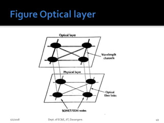
Prof.Amogha B,
Dept. of EC&E,
JIT, Davangere.
OpticalAmplifiers
 Optical amplifiers,
 Basic applications and types,
 Semiconductor optical amplifiers, EDFA.
OPTICAL NETWORKS: Introduction,
 SONET / SDH, Optical Interfaces,
 SONET/SDH rings, High – speed light
waveguides
1/1/2018 Dept. of EC&E, JIT, Davangere. 2
 Traditional Power budget were considered while
making a optical link. Repeaters are used when
power margin loss is more.
 To amplify: photon to electron generation working
on electrical reshaping and then convert to photon.
 A same process is applied for modern single
wavelength operated devices but its costly and
complex for multi-wavelength operated devices.
1/1/2018 3Dept. of EC&E, JIT, Davangere.
 Optical amplifiers applications vary from ultra-long
underground links to short range communication.
 Longer wavelength posses spectral response range
and highly reliable.
 Shorter wavelength are carried on metro and access
network links but wavelength can be altered based on
customer’s demands.
 Designed to recover quickly from rapid input power
variations as sudden channels changes.
1/1/2018 4Dept. of EC&E, JIT, Davangere.
 Three classes of the amplifiers applications
are there namely
 In-line optical amplifiers.
 Pre-amplifiers
 Power amplifiers
1/1/2018 Dept. of EC&E, JIT, Davangere. 5
1/1/2018 Dept. of EC&E, JIT, Davangere. 6
 In a single mode link, the effects of fiber
dispersion may be small so that limitation to
repeater spacing is fiber attenuation.
 There is no need of complete regeneration of
signal, a simple amplification of optical signal is
sufficient.
 An inline amplifiers used to decrease the
transmission loss and increase the distance
between repeaters by enhancing power levels.
1/1/2018 Dept. of EC&E, JIT, Davangere. 7
 Used as front-end amplifiers for an optical
receiver where weak signals are amplified
before photo-detection.
 Decrease in SNR by thermal noise at the
receiver side can be minimized considerably.
 Provides a higher gain factor compared to
other amplifiers.
1/1/2018 Dept. of EC&E, JIT, Davangere. 8
 To boost the transmitted signal at the
transmitters the power amplifiers are used.
 Increases the transmission distance from 10
to 100km based on value of amplifier gain
and fiber losses.
 Combination of pre-amplifiers and boosting
technique can achieve undersea
communication without repeaters(300km).
1/1/2018 Dept. of EC&E, JIT, Davangere. 9
 A passive star coupler is used to multiplex a
single input port to several output ports.
 It take cares about the power splitter loss and
coupler insertion loss.
1/1/2018 Dept. of EC&E, JIT, Davangere. 10
 Three main types of amplifiers are
 Semiconductor OpticalAmplifiers(SOA)
 Doped Fiber Amplifier.(DFA)
 Raman Amplifiers.
 All amplifiers increases power level of incident light through
stimulated emission or optical power transfer.
 Optical amplifiers are nothing but a laser without feedback.
 These just boosts the signals but unable to produce coherent
output. ( Ex: Reference source in DAC a 5V for reference but if
we connect load it unable to reproduce the same)
1/1/2018 Dept. of EC&E, JIT, Davangere. 11
1/1/2018 Dept. of EC&E, JIT, Davangere. 12
 The device absorbs the energy from external source
which is called as pump to active medium.
 Due to pumping action the population inversion
occur(higher orbit) in active medium.
 An incoming signal photon makes the stimulated
emission process.
 The falling electrons emits the electron hence the
optical amplifications happens.
1/1/2018 Dept. of EC&E, JIT, Davangere. 13
 Posses high gain response.
 Can be used both for switching and signal
processing functions in optical network.
 Limitations is the gain changes at particular
wavelength due to rapid change in carrier response.
 Rapid gain response leads to crosstalk while
amplification.
1/1/2018 Dept. of EC&E, JIT, Davangere. 14
 The active medium is made up of lightly doped SiO2
with erbium during the fabrication of core of the fiber.
 The advantage is pumping of the devices at several
different wavelength and has low coupling loss.
 Posses high bit rate and less dispersion for broad
spectrum from 1530 to 1560 nm.
 Posses less cross talk between the electronic
components.
1/1/2018 Dept. of EC&E, JIT, Davangere. 15
 Stimulated Raman scattering is the principle used in these kinds of
amplifiers.
 The gain for Raman amplifiers are through lump amplifiers or by
distributed amplifier.
 Lump amplifiers with a pump lasers are fitted to the small core
radius of 80m
 Distributed amplifiers any wavelength of sources can be used as
last 20 to 40km of fiber is converted to pre-amplifiers.
 Types are
 Erbium doped fiber amplifiers and
 Travelling wave amplifiers
1/1/2018 Dept. of EC&E, JIT, Davangere. 16
 These are optical networks which are used for
signal processing and switching functions.
 The signal rate is fluctuating due to rapid
change in carrier response and also effects
the signal gain for all wavelength.
 The crosstalk effects during the amplification
of broad spectrum due to rapid change in
carrier frequency.
1/1/2018 Dept. of EC&E, JIT, Davangere. 17
 The active medium prepared by doping the
rare earth metals with 10-30m length of optical
fiber.
 The fiber material can be silica, fluoride based
glass.
 The popular rare earth material is erbium.
 It is operated in the range 1530 to 1560 nm
1/1/2018 Dept. of EC&E, JIT, Davangere. 18
 Optical pumping : an external current (photon) is
used to push the electrons from lower to higher
energy level.
 The three energy levels are used in optical
pumping.
 Stimulated emission.
 Top level: More than a desired laser level(population
inversion)
 Middle level: Meta-stable state
 Normal state: all the energy are fed back in the form
of new photon
1/1/2018 Dept. of EC&E, JIT, Davangere. 19
 From pump source to ground energy level
1.27ev band-gap separation.
 0.841 separation between ground and top
layer of metastable
 Bottom layer of metable and ground is of
0.814ev
 Bottom layer of metable and top of bottom
layer is 0.775ev.
1/1/2018 Dept. of EC&E, JIT, Davangere. 20
1/1/2018 Dept. of EC&E, JIT, Davangere. 21
 Process1
 Process2
 Process3
 Process 4
 Process5
 Process6
 Process7
1/1/2018 Dept. of EC&E, JIT, Davangere. 23
 Pumping to active medium based on several
different wavelength.
 Low coupling loss
 Has a constant gain.
 Absorption and emission depends on glass
composition and dopants.
1/1/2018 Dept. of EC&E, JIT, Davangere. 24
1/1/2018 Dept. of EC&E, JIT, Davangere. 25
 Consists of doped fiber, pump lasers,
couplers(tap and passive wavelength), optical
isolators.
 Di-chronic coupler combines the pump and
signal power into amplifiers of different
wavelength
 Tap couplers is wavelength splitting ratio
with 99:1 to 95:5(Used to compare incoming
signal with output power)
1/1/2018 Dept. of EC&E, JIT, Davangere. 26
 Optical isolators avoids the back
propagation of amplified signal.
 Pumping of lasers posses two types based on
the direction of pumping towards signal path
namely
 Co-directional pumping.
 Counter pumping.
 Dual pump schemes posses two pumping
lasers which has 35 db gain
1/1/2018 Dept. of EC&E, JIT, Davangere. 27
1/1/2018 Dept. of EC&E, JIT, Davangere. 28
 Counter directional pumping- Provides higher
gain .
 Co-directional pumping has better noise
performance at 980nm
 Larger population inversion occurs at
1480nm.
1/1/2018 Dept. of EC&E, JIT, Davangere. 29
 Output signal of any amplifiers increases which saturates
the gain of amplifiers.
 Gain of the amplifiers depends on population inversion as
shown in graph.
 The fundamental physics law: The energy extracted from
source should be less than pump power stored in device.
 The in-equality in equation tells the possibility of pump
photons are lost due to interaction with impurities or
spontaneous emission in the pump energy
1/1/2018 Dept. of EC&E, JIT, Davangere. 30
1/1/2018 Dept. of EC&E, JIT, Davangere. 31
 Links operating at 10Gb/s
 Links operating at 160Gb/s
 Links operating at 40Gb/s
1/1/2018 Dept. of EC&E, JIT, Davangere. 33
1/1/2018 Dept. of EC&E, JIT, Davangere. 34
 Optical fibers are used to connect a wide range of
applications varies in transmission capacity and
speed.
 The connection can vary from shorter distance to
connecting two countries via ocean.
 Increase in the usage of optical fiber has increased
in every field and devices(Hardware : Computer
storage devices) also supports high speed
1/1/2018 Dept. of EC&E, JIT, Davangere. 35
 Basic terminology and general networks:
Four transmission implementation.( Long,
metro, access and LAN)
 Topology of the network, SONET and SDH
 Physical layer of SONET/SDH.
1/1/2018 Dept. of EC&E, JIT, Davangere. 36
 Different network architecture: defines the
network terminology (Figure)
1/1/2018 Dept. of EC&E, JIT, Davangere. 37
 Stations: Collection of devices that are
connected to network for communication
purpose. Ex: computers, router, printer, fax etc
 Networks: To establish the connection between
the stations, transmission paths are used to
make the interconnection between them.
 Node: Is a point where one or more
communication lines meets and used to
connect to stations.
1/1/2018 Dept. of EC&E, JIT, Davangere. 38
 Trunk: is a term used to refer a transmission line which
connects nodes or network.
 Used for carrying large traffic loads.
 Topology: It is the logical manner in which all the
nodes are connected together to form a channels of
network to carry information.
 Switching and routing: Transfer the information from
source to destination through series of intermediate
node is called as switching. Selecting the specific
path for reaching destination is called as routing.
1/1/2018 Dept. of EC&E, JIT, Davangere. 39
 Local Area Network(LAN)
 A network used to connect the shorter distance
customers or area.
 Ex: Office building, campus.
 In networking domain campus refers that
something which is at lesser distance.
 LANs are usually owned, used and operated
by a single person/ organization.
1/1/2018 Dept. of EC&E, JIT, Davangere. 40
 Commonly called as metro networks.
 The range of coverage is usually large
compared to LAN, it connects whole building,
entire city.
 These MANs are operated by the
telecommunication organization
1/1/2018 Dept. of EC&E, JIT, Davangere. 41
 Covers a large geographical area.
 Used for connecting between two cities
 Example: Undersea lines are used.
 These networks are owned and control by
private organizations or telecommunication
service providers
1/1/2018 Dept. of EC&E, JIT, Davangere. 42
 Enterprise networks are owned and operated
by a private organization.
 Important thing is it can be used by members
of that organization.
 Public networks are owned by telecom
service provider which are used by public
people ex: leased lines or dedicated lines.
1/1/2018 Dept. of EC&E, JIT, Davangere. 43
 Central Office
 Backbone
 Long haul Network
 Passive optical network: Optical distribution
network doesn’t posses optoelectronic
components used to provide access. Used to
get connection between fiber to network.
1/1/2018 Dept. of EC&E, JIT, Davangere. 44
1/1/2018 Dept. of EC&E, JIT, Davangere. 45
1/1/2018 Dept. of EC&E, JIT, Davangere. 46
 We know that physical layer provides the
physical connection between nodes but optical
layer provides the light path service over the
link.
 A lightpath is an end to end optical connection
that pass through several intermediate node.
 It supports wavelength switching, multiplexing,
adding and dropping of wavelength
1/1/2018 Dept. of EC&E, JIT, Davangere. 48
1/1/2018 Dept. of EC&E, JIT, Davangere. 49
 SONET stands for synchronous optical network.
 Except in North America it is called as SONET in rest
parts of the world it is called as Synchronous Digital
Hierarch (SDH).
 Covers basic concepts of SONET, optical interface and
network implementations.
 Frame format of SONET/SDH.
1/1/2018 Dept. of EC&E, JIT, Davangere. 50
1/1/2018 Dept. of EC&E, JIT, Davangere. 51
 STS( Synchronous Transport Signal) all other
series of SONET is the integer multiple of 51.84
Mb/s i.e. STS-N.
 STS-N signal is used to modulate the optical
source.
 To avoid long 0’s and 1’s the logical STS-N is
scrambled.
 After conversion from electrical to optical the
output from physical layer is called as OC-
N(Optical Carrier) N ranges from 1-768.
1/1/2018 Dept. of EC&E, JIT, Davangere. 52
 In SDH the basic rate is STS-3 (155.52Mb/s)-
STS(SynchronousTransport Module)
 STS 1 – Level 1 for general STS-M.
 SDH doesn’t makes a difference between
logical electrical signal and optical signal
1/1/2018 Dept. of EC&E, JIT, Davangere. 53
1/1/2018 Dept. of EC&E, JIT, Davangere. 54
1/1/2018 Dept. of EC&E, JIT, Davangere. 55
 First 3 columns carry network management
information( transport overhead).
 Next 87 columns are Synchronous Payload
Envelope carries user data and 9 bytes has path
overhead (POH).
 POH monitors the signal labeling, status,
tracking function.
 This 9 bytes (POH) can be placed anywhere in
the frame.
 Individual add or drop in the SONET/SDH is
feasible feature.
1/1/2018 Dept. of EC&E, JIT, Davangere. 56
1/1/2018 Dept. of EC&E, JIT, Davangere. 57
 N greater than 1 is going to add the number
of columns multiplied by 3. 3*3=9.
 9 columns has transport overhead.
 90*N(3) is left for carrying data frames.
1/1/2018 Dept. of EC&E, JIT, Davangere. 58
 By using the STS- N frame format the data
speed can be achieved to certain extend
 For higher speed we are moving for STM-M
 Where N=3M; M=1,4,16 and 64is as same as
SONET N but N=3M (N=3, 12, 48 and 192)
1/1/2018 Dept. of EC&E, JIT, Davangere. 59
1/1/2018 Dept. of EC&E, JIT, Davangere. 60
 To get the interconnection between the
equipments of different manufactures with
the SONET/ SDH.
1/1/2018 Dept. of EC&E, JIT, Davangere. 61
1/1/2018 Dept. of EC&E, JIT, Davangere. 64
 SONET/SDH is configured as mesh or ring
like structure.
 In order to connect equipments and
overcome the faulty devices a loop like
structures are used.
 It is also called as self- healing ring, the traffic
flow can automatically switched to alternate
or standby path due to faulty path.
1/1/2018 Dept. of EC&E, JIT, Davangere. 65
 Features
1) It contains 2 or 4 rings running between nodes
(can make eight possible structure).
2) Operating signals can travel either in clockwise
direction(uni-directional ring) or anti-clockwise
direction(bi-directional ring).
3) During link failure the signals are transformed
using the protective ring.
1/1/2018 Dept. of EC&E, JIT, Davangere. 66
 Out of eight combination the popular two
structures explained
1. Two fiber Uni-directional path switched ring
(UPSR)
2. Two fiber or four fiber, Bi-directional path
switched ring(BLSR).
1/1/2018 Dept. of EC&E, JIT, Davangere. 67
1/1/2018 Dept. of EC&E, JIT, Davangere. 68
 Primary ring- clock wise direction
 Protection ring – counter clock wise
direction(anti-clock wise direction).
 Node 1 to node 3 transfer of signals
1/1/2018 Dept. of EC&E, JIT, Davangere. 69
1/1/2018 Dept. of EC&E, JIT, Davangere. 70
1/1/2018 Dept. of EC&E, JIT, Davangere. 71
1/1/2018 Dept. of EC&E, JIT, Davangere. 72
1/1/2018 Dept. of EC&E, JIT, Davangere. 73

Optical amplifiers and networking

  • 1.
    Prof.Amogha B, Dept. ofEC&E, JIT, Davangere.
  • 2.
    OpticalAmplifiers  Optical amplifiers, Basic applications and types,  Semiconductor optical amplifiers, EDFA. OPTICAL NETWORKS: Introduction,  SONET / SDH, Optical Interfaces,  SONET/SDH rings, High – speed light waveguides 1/1/2018 Dept. of EC&E, JIT, Davangere. 2
  • 3.
     Traditional Powerbudget were considered while making a optical link. Repeaters are used when power margin loss is more.  To amplify: photon to electron generation working on electrical reshaping and then convert to photon.  A same process is applied for modern single wavelength operated devices but its costly and complex for multi-wavelength operated devices. 1/1/2018 3Dept. of EC&E, JIT, Davangere.
  • 4.
     Optical amplifiersapplications vary from ultra-long underground links to short range communication.  Longer wavelength posses spectral response range and highly reliable.  Shorter wavelength are carried on metro and access network links but wavelength can be altered based on customer’s demands.  Designed to recover quickly from rapid input power variations as sudden channels changes. 1/1/2018 4Dept. of EC&E, JIT, Davangere.
  • 5.
     Three classesof the amplifiers applications are there namely  In-line optical amplifiers.  Pre-amplifiers  Power amplifiers 1/1/2018 Dept. of EC&E, JIT, Davangere. 5
  • 6.
    1/1/2018 Dept. ofEC&E, JIT, Davangere. 6
  • 7.
     In asingle mode link, the effects of fiber dispersion may be small so that limitation to repeater spacing is fiber attenuation.  There is no need of complete regeneration of signal, a simple amplification of optical signal is sufficient.  An inline amplifiers used to decrease the transmission loss and increase the distance between repeaters by enhancing power levels. 1/1/2018 Dept. of EC&E, JIT, Davangere. 7
  • 8.
     Used asfront-end amplifiers for an optical receiver where weak signals are amplified before photo-detection.  Decrease in SNR by thermal noise at the receiver side can be minimized considerably.  Provides a higher gain factor compared to other amplifiers. 1/1/2018 Dept. of EC&E, JIT, Davangere. 8
  • 9.
     To boostthe transmitted signal at the transmitters the power amplifiers are used.  Increases the transmission distance from 10 to 100km based on value of amplifier gain and fiber losses.  Combination of pre-amplifiers and boosting technique can achieve undersea communication without repeaters(300km). 1/1/2018 Dept. of EC&E, JIT, Davangere. 9
  • 10.
     A passivestar coupler is used to multiplex a single input port to several output ports.  It take cares about the power splitter loss and coupler insertion loss. 1/1/2018 Dept. of EC&E, JIT, Davangere. 10
  • 11.
     Three maintypes of amplifiers are  Semiconductor OpticalAmplifiers(SOA)  Doped Fiber Amplifier.(DFA)  Raman Amplifiers.  All amplifiers increases power level of incident light through stimulated emission or optical power transfer.  Optical amplifiers are nothing but a laser without feedback.  These just boosts the signals but unable to produce coherent output. ( Ex: Reference source in DAC a 5V for reference but if we connect load it unable to reproduce the same) 1/1/2018 Dept. of EC&E, JIT, Davangere. 11
  • 12.
    1/1/2018 Dept. ofEC&E, JIT, Davangere. 12
  • 13.
     The deviceabsorbs the energy from external source which is called as pump to active medium.  Due to pumping action the population inversion occur(higher orbit) in active medium.  An incoming signal photon makes the stimulated emission process.  The falling electrons emits the electron hence the optical amplifications happens. 1/1/2018 Dept. of EC&E, JIT, Davangere. 13
  • 14.
     Posses highgain response.  Can be used both for switching and signal processing functions in optical network.  Limitations is the gain changes at particular wavelength due to rapid change in carrier response.  Rapid gain response leads to crosstalk while amplification. 1/1/2018 Dept. of EC&E, JIT, Davangere. 14
  • 15.
     The activemedium is made up of lightly doped SiO2 with erbium during the fabrication of core of the fiber.  The advantage is pumping of the devices at several different wavelength and has low coupling loss.  Posses high bit rate and less dispersion for broad spectrum from 1530 to 1560 nm.  Posses less cross talk between the electronic components. 1/1/2018 Dept. of EC&E, JIT, Davangere. 15
  • 16.
     Stimulated Ramanscattering is the principle used in these kinds of amplifiers.  The gain for Raman amplifiers are through lump amplifiers or by distributed amplifier.  Lump amplifiers with a pump lasers are fitted to the small core radius of 80m  Distributed amplifiers any wavelength of sources can be used as last 20 to 40km of fiber is converted to pre-amplifiers.  Types are  Erbium doped fiber amplifiers and  Travelling wave amplifiers 1/1/2018 Dept. of EC&E, JIT, Davangere. 16
  • 17.
     These areoptical networks which are used for signal processing and switching functions.  The signal rate is fluctuating due to rapid change in carrier response and also effects the signal gain for all wavelength.  The crosstalk effects during the amplification of broad spectrum due to rapid change in carrier frequency. 1/1/2018 Dept. of EC&E, JIT, Davangere. 17
  • 18.
     The activemedium prepared by doping the rare earth metals with 10-30m length of optical fiber.  The fiber material can be silica, fluoride based glass.  The popular rare earth material is erbium.  It is operated in the range 1530 to 1560 nm 1/1/2018 Dept. of EC&E, JIT, Davangere. 18
  • 19.
     Optical pumping: an external current (photon) is used to push the electrons from lower to higher energy level.  The three energy levels are used in optical pumping.  Stimulated emission.  Top level: More than a desired laser level(population inversion)  Middle level: Meta-stable state  Normal state: all the energy are fed back in the form of new photon 1/1/2018 Dept. of EC&E, JIT, Davangere. 19
  • 20.
     From pumpsource to ground energy level 1.27ev band-gap separation.  0.841 separation between ground and top layer of metastable  Bottom layer of metable and ground is of 0.814ev  Bottom layer of metable and top of bottom layer is 0.775ev. 1/1/2018 Dept. of EC&E, JIT, Davangere. 20
  • 21.
    1/1/2018 Dept. ofEC&E, JIT, Davangere. 21
  • 22.
     Process1  Process2 Process3  Process 4  Process5  Process6  Process7 1/1/2018 Dept. of EC&E, JIT, Davangere. 23
  • 23.
     Pumping toactive medium based on several different wavelength.  Low coupling loss  Has a constant gain.  Absorption and emission depends on glass composition and dopants. 1/1/2018 Dept. of EC&E, JIT, Davangere. 24
  • 24.
    1/1/2018 Dept. ofEC&E, JIT, Davangere. 25
  • 25.
     Consists ofdoped fiber, pump lasers, couplers(tap and passive wavelength), optical isolators.  Di-chronic coupler combines the pump and signal power into amplifiers of different wavelength  Tap couplers is wavelength splitting ratio with 99:1 to 95:5(Used to compare incoming signal with output power) 1/1/2018 Dept. of EC&E, JIT, Davangere. 26
  • 26.
     Optical isolatorsavoids the back propagation of amplified signal.  Pumping of lasers posses two types based on the direction of pumping towards signal path namely  Co-directional pumping.  Counter pumping.  Dual pump schemes posses two pumping lasers which has 35 db gain 1/1/2018 Dept. of EC&E, JIT, Davangere. 27
  • 27.
    1/1/2018 Dept. ofEC&E, JIT, Davangere. 28
  • 28.
     Counter directionalpumping- Provides higher gain .  Co-directional pumping has better noise performance at 980nm  Larger population inversion occurs at 1480nm. 1/1/2018 Dept. of EC&E, JIT, Davangere. 29
  • 29.
     Output signalof any amplifiers increases which saturates the gain of amplifiers.  Gain of the amplifiers depends on population inversion as shown in graph.  The fundamental physics law: The energy extracted from source should be less than pump power stored in device.  The in-equality in equation tells the possibility of pump photons are lost due to interaction with impurities or spontaneous emission in the pump energy 1/1/2018 Dept. of EC&E, JIT, Davangere. 30
  • 30.
    1/1/2018 Dept. ofEC&E, JIT, Davangere. 31
  • 31.
     Links operatingat 10Gb/s  Links operating at 160Gb/s  Links operating at 40Gb/s 1/1/2018 Dept. of EC&E, JIT, Davangere. 33
  • 32.
    1/1/2018 Dept. ofEC&E, JIT, Davangere. 34
  • 33.
     Optical fibersare used to connect a wide range of applications varies in transmission capacity and speed.  The connection can vary from shorter distance to connecting two countries via ocean.  Increase in the usage of optical fiber has increased in every field and devices(Hardware : Computer storage devices) also supports high speed 1/1/2018 Dept. of EC&E, JIT, Davangere. 35
  • 34.
     Basic terminologyand general networks: Four transmission implementation.( Long, metro, access and LAN)  Topology of the network, SONET and SDH  Physical layer of SONET/SDH. 1/1/2018 Dept. of EC&E, JIT, Davangere. 36
  • 35.
     Different networkarchitecture: defines the network terminology (Figure) 1/1/2018 Dept. of EC&E, JIT, Davangere. 37
  • 36.
     Stations: Collectionof devices that are connected to network for communication purpose. Ex: computers, router, printer, fax etc  Networks: To establish the connection between the stations, transmission paths are used to make the interconnection between them.  Node: Is a point where one or more communication lines meets and used to connect to stations. 1/1/2018 Dept. of EC&E, JIT, Davangere. 38
  • 37.
     Trunk: isa term used to refer a transmission line which connects nodes or network.  Used for carrying large traffic loads.  Topology: It is the logical manner in which all the nodes are connected together to form a channels of network to carry information.  Switching and routing: Transfer the information from source to destination through series of intermediate node is called as switching. Selecting the specific path for reaching destination is called as routing. 1/1/2018 Dept. of EC&E, JIT, Davangere. 39
  • 38.
     Local AreaNetwork(LAN)  A network used to connect the shorter distance customers or area.  Ex: Office building, campus.  In networking domain campus refers that something which is at lesser distance.  LANs are usually owned, used and operated by a single person/ organization. 1/1/2018 Dept. of EC&E, JIT, Davangere. 40
  • 39.
     Commonly calledas metro networks.  The range of coverage is usually large compared to LAN, it connects whole building, entire city.  These MANs are operated by the telecommunication organization 1/1/2018 Dept. of EC&E, JIT, Davangere. 41
  • 40.
     Covers alarge geographical area.  Used for connecting between two cities  Example: Undersea lines are used.  These networks are owned and control by private organizations or telecommunication service providers 1/1/2018 Dept. of EC&E, JIT, Davangere. 42
  • 41.
     Enterprise networksare owned and operated by a private organization.  Important thing is it can be used by members of that organization.  Public networks are owned by telecom service provider which are used by public people ex: leased lines or dedicated lines. 1/1/2018 Dept. of EC&E, JIT, Davangere. 43
  • 42.
     Central Office Backbone  Long haul Network  Passive optical network: Optical distribution network doesn’t posses optoelectronic components used to provide access. Used to get connection between fiber to network. 1/1/2018 Dept. of EC&E, JIT, Davangere. 44
  • 43.
    1/1/2018 Dept. ofEC&E, JIT, Davangere. 45
  • 44.
    1/1/2018 Dept. ofEC&E, JIT, Davangere. 46
  • 45.
     We knowthat physical layer provides the physical connection between nodes but optical layer provides the light path service over the link.  A lightpath is an end to end optical connection that pass through several intermediate node.  It supports wavelength switching, multiplexing, adding and dropping of wavelength 1/1/2018 Dept. of EC&E, JIT, Davangere. 48
  • 46.
    1/1/2018 Dept. ofEC&E, JIT, Davangere. 49
  • 47.
     SONET standsfor synchronous optical network.  Except in North America it is called as SONET in rest parts of the world it is called as Synchronous Digital Hierarch (SDH).  Covers basic concepts of SONET, optical interface and network implementations.  Frame format of SONET/SDH. 1/1/2018 Dept. of EC&E, JIT, Davangere. 50
  • 48.
    1/1/2018 Dept. ofEC&E, JIT, Davangere. 51
  • 49.
     STS( SynchronousTransport Signal) all other series of SONET is the integer multiple of 51.84 Mb/s i.e. STS-N.  STS-N signal is used to modulate the optical source.  To avoid long 0’s and 1’s the logical STS-N is scrambled.  After conversion from electrical to optical the output from physical layer is called as OC- N(Optical Carrier) N ranges from 1-768. 1/1/2018 Dept. of EC&E, JIT, Davangere. 52
  • 50.
     In SDHthe basic rate is STS-3 (155.52Mb/s)- STS(SynchronousTransport Module)  STS 1 – Level 1 for general STS-M.  SDH doesn’t makes a difference between logical electrical signal and optical signal 1/1/2018 Dept. of EC&E, JIT, Davangere. 53
  • 51.
    1/1/2018 Dept. ofEC&E, JIT, Davangere. 54
  • 52.
    1/1/2018 Dept. ofEC&E, JIT, Davangere. 55
  • 53.
     First 3columns carry network management information( transport overhead).  Next 87 columns are Synchronous Payload Envelope carries user data and 9 bytes has path overhead (POH).  POH monitors the signal labeling, status, tracking function.  This 9 bytes (POH) can be placed anywhere in the frame.  Individual add or drop in the SONET/SDH is feasible feature. 1/1/2018 Dept. of EC&E, JIT, Davangere. 56
  • 54.
    1/1/2018 Dept. ofEC&E, JIT, Davangere. 57
  • 55.
     N greaterthan 1 is going to add the number of columns multiplied by 3. 3*3=9.  9 columns has transport overhead.  90*N(3) is left for carrying data frames. 1/1/2018 Dept. of EC&E, JIT, Davangere. 58
  • 56.
     By usingthe STS- N frame format the data speed can be achieved to certain extend  For higher speed we are moving for STM-M  Where N=3M; M=1,4,16 and 64is as same as SONET N but N=3M (N=3, 12, 48 and 192) 1/1/2018 Dept. of EC&E, JIT, Davangere. 59
  • 57.
    1/1/2018 Dept. ofEC&E, JIT, Davangere. 60
  • 58.
     To getthe interconnection between the equipments of different manufactures with the SONET/ SDH. 1/1/2018 Dept. of EC&E, JIT, Davangere. 61
  • 59.
    1/1/2018 Dept. ofEC&E, JIT, Davangere. 64
  • 60.
     SONET/SDH isconfigured as mesh or ring like structure.  In order to connect equipments and overcome the faulty devices a loop like structures are used.  It is also called as self- healing ring, the traffic flow can automatically switched to alternate or standby path due to faulty path. 1/1/2018 Dept. of EC&E, JIT, Davangere. 65
  • 61.
     Features 1) Itcontains 2 or 4 rings running between nodes (can make eight possible structure). 2) Operating signals can travel either in clockwise direction(uni-directional ring) or anti-clockwise direction(bi-directional ring). 3) During link failure the signals are transformed using the protective ring. 1/1/2018 Dept. of EC&E, JIT, Davangere. 66
  • 62.
     Out ofeight combination the popular two structures explained 1. Two fiber Uni-directional path switched ring (UPSR) 2. Two fiber or four fiber, Bi-directional path switched ring(BLSR). 1/1/2018 Dept. of EC&E, JIT, Davangere. 67
  • 63.
    1/1/2018 Dept. ofEC&E, JIT, Davangere. 68
  • 64.
     Primary ring-clock wise direction  Protection ring – counter clock wise direction(anti-clock wise direction).  Node 1 to node 3 transfer of signals 1/1/2018 Dept. of EC&E, JIT, Davangere. 69
  • 65.
    1/1/2018 Dept. ofEC&E, JIT, Davangere. 70
  • 66.
    1/1/2018 Dept. ofEC&E, JIT, Davangere. 71
  • 67.
    1/1/2018 Dept. ofEC&E, JIT, Davangere. 72
  • 68.
    1/1/2018 Dept. ofEC&E, JIT, Davangere. 73

Editor's Notes

  • #4 Traditional repeaters: While making a optical link, Power budget is calculated and adds the repeaters when the power loss exceeds the power margin. Conventional amplifiers uses conversion to electron and then perform electrical amplification, re-shaping, pulse shaping.
  • #5 In long distance underground sea and terrestrial point to point the traffic pattern are relatively stable hence the input power levels to amplifier is constant.
  • #9 Front end amplifiers are used mainly at receiver end to enhance the SNR value.
  • #12 SOA AND DFA uses the same process for population inversion as same as laser device but with out feedback
  • #14 Falling of electrons is by a single photon while falling a similar energy left is the amplification process.
  • #20 Three energy levels: top level the excited electrons posses more energy than the laser after some time 9ms it falls to metastable state a same energy of laser, due to same energy the stimulated emission takes place.
  • #27 2. 980/1550 nm and 1480/1550nm
  • #46 Central office: A temporary connection between users, network
  • #51 After invention of Optical fiber transmission the research made up mind to come up with the new signal standards in digital time division multiplexing called as SONET.