Download to read offline


![MEMB113 | Dept. of Mechanical Engineering | UNITEN | 200509AutoCADPart2
Block and insert
• Block and insert is similar to copy and paste, but with extra features,
where objects can be copied and inserted into the drawing
• Steps
– Create block [pd menu] >Block > Make
or click [Icon Block]
– Give name, select objects to be included
– To insert/paste block into drawing
– [pd menu] > Insert > Block or
click [Icon Insert Block]
– Specify insertion point on drawing to paste
Base point
(1) Give name
(2) Base point
(3) Select objects
Block (make)
Insert block](https://image.slidesharecdn.com/osnapdhruvit-150130114751-conversion-gate01/85/object-snap-8-320.jpg)
![MEMB113 | Dept. of Mechanical Engineering | UNITEN | 200509AutoCADPart2
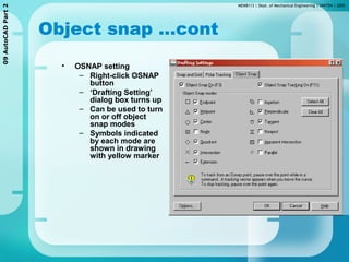
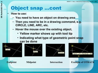
Block & insert ... cont
• To use/paste the block in drawing
– [pd menu] > Insert > Block.. Or [Icon
Insert Block]
– command:insert {enter}
Insert icon
Select block
Insertion point Scale Rotation](https://image.slidesharecdn.com/osnapdhruvit-150130114751-conversion-gate01/85/object-snap-9-320.jpg)
![MEMB113 | Dept. of Mechanical Engineering | UNITEN | 200509AutoCADPart2
Rectangle
• To draw a rectangular object
– [pd menu] > Draw > Rectangle or [Icon
Rectangle] or Command:rectangle or rectang
Rectangle shape
Rectangle – with 0.25 chamfer
Rectangle – with 0.25 fillet
2nd point1st point
Rectangle icon](https://image.slidesharecdn.com/osnapdhruvit-150130114751-conversion-gate01/85/object-snap-10-320.jpg)
![MEMB113 | Dept. of Mechanical Engineering | UNITEN | 200509AutoCADPart2
Polygon
• To draw many- & equal- side closed object e.g hexagon,
pentagon etc.
– [pd menu] > Draw > Polygon or [Icon Polygon] or
Command: polygon
Center - Inscribed
Center - Circumscribed Edge
1st point
2nd point
1st point
2nd point
1st point
2nd point
Examples of polygon drawn
Polygon icon](https://image.slidesharecdn.com/osnapdhruvit-150130114751-conversion-gate01/85/object-snap-11-320.jpg)
![MEMB113 | Dept. of Mechanical Engineering | UNITEN | 200509AutoCADPart2
Offset
• To create copy of existing object at a certain distance
– Concentric circles and squares, parallel lines and
curves
– [pd menu] > Modify > Offset or [Icon Offset]
– Specify the distance
– Select the object
– Click on the side to place the object
Before After
Offset icon
Before After
Before After](https://image.slidesharecdn.com/osnapdhruvit-150130114751-conversion-gate01/85/object-snap-12-320.jpg)
![MEMB113 | Dept. of Mechanical Engineering | UNITEN | 200509AutoCADPart2
Trim
• To remove a certain part of an object based on other object(s)
– [pd menu] > Modify > Trim or [Icon Trim]
Cutting edge
Part to be removed
Before After
Cutting edgeBefore After
Part to be removed
Cutting edge
Part to be removed
Before After
Cutting edge
Part to be removed
Cutting edge
Part to be removed
Before After
Before After](https://image.slidesharecdn.com/osnapdhruvit-150130114751-conversion-gate01/85/object-snap-13-320.jpg)
![MEMB113 | Dept. of Mechanical Engineering | UNITEN | 200509AutoCADPart2
Extend
• To extend an object to another selected object
– [pd menu] > Modify > Extend or [Icon Extend] or
– command: extend
– Steps
• Active the command
• Click an object to be the boundary object
• The the object to be extended
• The object should extend to the boundary object
Boundary object
Before After Before After
Object to extend
Boundary object
Object to extend](https://image.slidesharecdn.com/osnapdhruvit-150130114751-conversion-gate01/85/object-snap-14-320.jpg)
![MEMB113 | Dept. of Mechanical Engineering | UNITEN | 200509AutoCADPart2
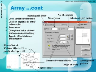
Array
• Creates multiple copies with a certain
pattern and distance
• 2 types: rectangular and polar
Rectangular array
– [pd menu] > Modify > Array…
– [icon Array]
– Array Window will be displayed
AfterBefore
Array icon](https://image.slidesharecdn.com/osnapdhruvit-150130114751-conversion-gate01/85/object-snap-15-320.jpg)
![MEMB113 | Dept. of Mechanical Engineering | UNITEN | 200509AutoCADPart2
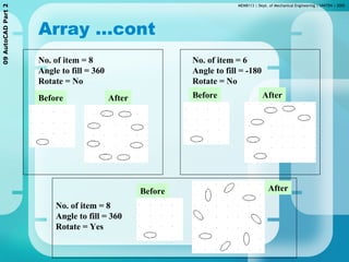
Array …cont
– Click on Polar Array
– Select object(s)
– Specify center point
– Select method
• No.of item & angle to
fill
• No.of item & angle
between item
• Angle to fill & angle
between item
– Specify the required
value
– Click on ‘rotate item as
copied’ check box if
required
Polar array
– [pd menu] > Modify > Array…
– [icon Array]](https://image.slidesharecdn.com/osnapdhruvit-150130114751-conversion-gate01/85/object-snap-17-320.jpg)


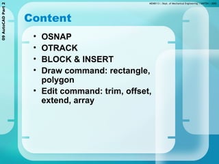
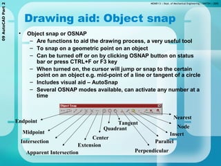
The document discusses various drawing aids and commands in AutoCAD including object snaps, blocks and inserts, and editing tools like offset, trim, extend, and array. Object snaps allow precise placement of drawing elements by snapping to geometric points on existing objects. Blocks allow grouping objects that can then be inserted multiple times. Common drawing tools like rectangle and polygon are covered as well as editing tools to modify objects.