Download to read offline

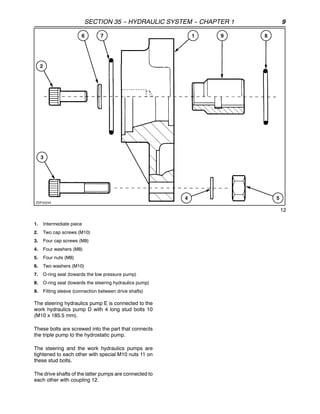
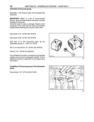
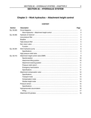
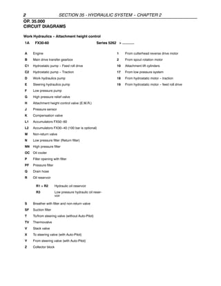
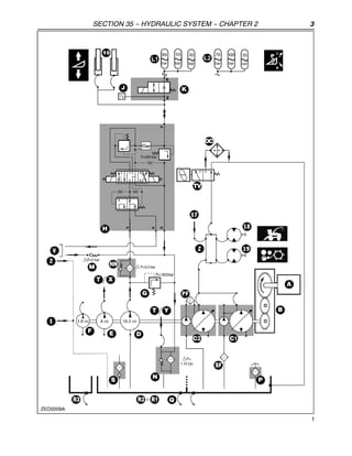
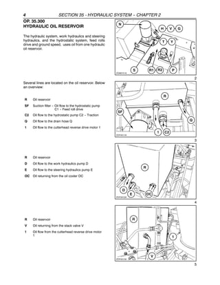

This document provides information on the hydraulic system for attachment height control on agricultural equipment. It includes circuit diagrams, component specifications, and descriptions of the operation of the work hydraulics pump, attachment height control valve, attachment compensation valve, and transport and compensation modes. Torque specifications are also provided for reassembling the hydraulic pump group.


