SlideShare a Scribd company logo
1 of 27
Download to read offline
Copyright © 2006 CNH America LLC.
All rights reserved.
Printed in U.S.A.
Issued March, 2006
CNH America LLC.
245 E NORTH AVENUE
CAROL STREAM, IL 60188 U.S.A. Bur 6-81170
W110 and W130 Wheel Loader
Service Manual
6-81160
Table of Contents
Description Section No. Form No.
General Tab 1
Section Index - General 6-81180
Standard Torque Specifications 1001 6-80470
Fluids and Lubricants 1002 6-81190
Metric Conversion Chart 1003 6-80690
Engines Tab 2
Section Index - Engines 6-81200
Engine and Radiator Removal and Installation 2000 6-81210
Stall Tests 2002 6-81220
For Engine Repair, See the Engine Service Manual 6-80940
Fuel System Tab 3
Section Index - Fuel System 6-81230
For Fuel System Repair, See the Engine Service Manual 6-80940
Electrical Tab 4
Section Index - Electrical 6-81240
Removal and Installation of Starter and Alternator 4001 6-81250
Electrical Specifications and Troubleshooting 4002 6-81260
Batteries 4003 6-81270
Instrument Cluster and Digital Display 4005 6-81280
Bur 6-81170 Issued 3-06 Printed in U.S.A.
Steering Tab 5
Section Index - Steering 6-81290
Removal and Installation of Steering Components 5001 6-81300
Steering Specifications, Pressure Checks, and Troubleshooting 5002 6-81310
Steering Control Valve 5003 6-81320
Auxiliary Steering Priority Valve 5004 6-81330
Steering Cylinders 5005 6-81340
Center Pivot 5006 6-81350
Auxiliary Steering Motor and Pump 5007 6-81360
Power Train Tab 6
Section Index - Power Train 6-81370
Removal and Installation of Power Train Components 6001 6-81380
Transmission Specifications, Pressure Checks, and Troubleshooting 6002 6-81390
Transmission 6003 6-81400
Front Axle 6004 6-81410
Rear Axle 6004 6-81420
Drive Shafts, Center Bearing, and Universal Joints 6005 6-81430
Wheels and Tires 6006 6-81440
Transmission Control Valve 6007 6-81450
Brakes Tab 7
Section Index - Brakes 6-81460
Removal and Installation of Brake Components 7001 6-81470
Hydraulic Brake Troubleshooting 7002 6-81480
Brake Accumulators 7004 6-81490
Parking Brake 7008 6-81500
Hydraulics Tab 8
Section Index - Hydraulics 6-81510
Removal and Installation of Hydraulic Components 8001 6-81520
Hydraulic Specifications, Troubleshooting, and Pressure Checks 8002 6-81530
Cleaning the Hydraulic System 8003 6-81540
Loader Control Valve 8005 6-81550
Cylinders 8006 6-81560
Coupler Solenoid Locking Valve 8007 6-81570
Pilot Pressure Accumulator and Ride Control Accumulator 8013 6-81580
Ride Control Valve 8014 6-81590
W110 and W130 Wheel Loader
Service Manual
6-81160
Table of Contents
Description Section No. Form No.
Copyright © 2006 CNH America LLC.
All rights reserved.
Printed in U.S.A.
Issued March, 2006
CNH America LLC.
245 E NORTH AVENUE
CAROL STREAM, IL 60188 U.S.A. Bur 6-81170
NOTE: CNH America LLC reserves the right to make improvements in design or
changes in specifications at any time without incurring any obligation to install
them on units previously sold.
Mounted Equipment Tab 9
Section Index - Mounted Equipment 6-81600
Pedal and Levers 9001 6-81610
Air Conditioning Troubleshooting and System Checks For Systems with HFC-134a
Refrigerant 9002 6-81620
Air Conditioner System Service 9003 6-81630
Removal and Installation of Air Conditioning and Heater Components 9004 6-81640
Loader 9006 6-81650
ROPS Cab and ROPS Canopy 9007 6-81660
Cab Glass Installation 9010 6-81670
Electrical Schematic Foldouts and Hydraulic Schematic Foldouts In Rear Pocket 6-81680
W110 and W130 Wheel Loader
Service Manual
6-81160
Table of Contents
Description Section No. Form No.
Copyright © 2006 CNH America LLC.
All rights reserved.
Printed in U.S.A.
Issued March, 2006
CNH America LLC.
245 E NORTH AVENUE
CAROL STREAM, IL 60188 U.S.A. Bur 6-81180
SECTION INDEX
GENERAL
Standard Torque Specifications. . . . . . . . . . . . . . . . . . . . . . . . . . . . . . . . . . . . . . . . . . . . . . . . . . . . . . . . . . . . . .1001
Fluids and Lubricants . . . . . . . . . . . . . . . . . . . . . . . . . . . . . . . . . . . . . . . . . . . . . . . . . . . . . . . . . . . . . . . . . . . . .1002
Metric Conversion Chart . . . . . . . . . . . . . . . . . . . . . . . . . . . . . . . . . . . . . . . . . . . . . . . . . . . . . . . . . . . . . . . . . . .1003
Section Title Section Number
Section
1001
1001
Copyright © 2006 CNH America LLC.
All rights reserved.
Printed in U.S.A.
Issued January, 2006
CNH America LLC.
245 E NORTH AVENUE
CAROL STREAM, IL 60188 U.S.A. Bur 6-80470
GENERAL TORQUE SPECIFICATIONS
1001-3
Bur 6-80470 Issued 1-06 Printed in U.S.A.
TORQUE SPECIFICATIONS - DECIMAL HARDWARE
Use the torques in this chart when special torques
are not given. These torques apply to fasteners with
both UNC and UNF threads as received from
suppliers dry, or when lubricated with engine oil. Not
applicable if special graphities, Molydisulfide
greases, or other extreme pressure lubricants are
used.
Grade 5 Bolts, Nuts, and Studs
Size
Pound-
Inches
Newton
metres
1/4 inch 108 to 132 12 to 15
5/16 inch 204 to 252 23 to 28
3/8 inch 420 to 504 48 to 57
Size
Pound-
Feet
Newton
metres
7/16 inch 54 to 64 73 to 87
1/2 inch 80 to 96 109 to 130
9/16 inch 110 to 132 149 to 179
5/8 inch 150 to 180 203 to 244
3/4 inch 270 to 324 366 to 439
7/8 inch 400 to 480 542 to 651
1.0 inch 580 to 696 787 to 944
1-1/8 inch 800 to 880 1085 to 1193
1-1/4 inch 1120 to 1240 1519 to 1681
1-3/8 inch 1460 to 1680 1980 to 2278
1-1/2 inch 1940 to 2200 2631 to 2983
Grade 8 Bolts, Nuts, and Studs
Size
Pound-
Inches
Newton
metres
1/4 inch 144 to 180 16 to 20
5/16 inch 288 to 348 33 to 39
3/8 inch 540 to 648 61 to 73
Size
Pound-
Feet
Newton
metres
7/16 inch 70 to 84 95 to 114
1/2 inch 110 to 132 149 to 179
9/16 inch 160 to 192 217 to 260
5/8 inch 220 to 264 298 to 358
3/4 inch 380 to 456 515 to 618
7/8 inch 600 to 720 814 to 976
1.0 inch 900 to 1080 1220 to 1465
1-1/8 inch 1280 to 1440 1736 to 1953
1-1/4 inch 1820 to 2000 2468 to 2712
1-3/8 inch 2380 to 2720 3227 to 3688
1-1/2 inch 3160 to 3560 4285 to 4827
NOTE: Use thick nuts with Grade 8 bolts.
1001-4
Bur 6-80470 Issued 1-06 Printed in U.S.A.
TORQUE SPECIFICATIONS - METRIC HARDWARE
Use the following torques when specifications are not
given.
These values apply to fasteners with coarse threads
as received from supplier, plated or unplated, or
when lubricated with engine oil. These values do not
apply if graphite or Molydisulfide grease or oil is
used.
Grade 12.9 Bolts, Nuts, and Studs
Usually the torque values specified for grade 10.9
fasteners can be used satisfactorily on grade 12.9
fasteners.
Grade 8.8 Bolts, Nuts, and Studs
Size
Pound-
Inches
Newton
metres
M4 24 to 36 3 to 4
M5 60 to 72 7 to 8
M6 96 to 108 11 to 12
M8 228 to 276 26 to 31
M10 456 to 540 52 to 61
Size
Pound-
Feet
Newton
metres
M12 66 to 79 90 to 107
M14 106 to 127 144 to 172
M16 160 to 200 217 to 271
M20 320 to 380 434 to 515
M24 500 to 600 675 to 815
M30 920 to 1100 1250 to 1500
M36 1600 to 1950 2175 to 2600
8.8
Grade 10.9 Bolts, Nuts, and Studs
Size
Pound-
Inches
Newton
metres
M4 36 to 48 4 to 5
M5 84 to 96 9 to 11
M6 132 to 156 15 to 18
M8 324 to 384 37 to 43
Size
Pound-
Feet
Newton
metres
M10 54 to 64 73 to 87
M12 93 to 112 125 to 150
M14 149 to 179 200 to 245
M16 230 to 280 310 to 380
M20 450 to 540 610 to 730
M24 780 to 940 1050 to 1275
M30 1470 to 1770 2000 to 2400
M36 2580 to 3090 3500 to 4200
10.9
12.9
1001-5
Bur 6-80470 Issued 1-06 Printed in U.S.A.
TORQUE SPECIFICATIONS - STEEL HYDRAULIC FITTINGS
37 Degree Flare Fitting
Tube OD
Hose ID
Thread
Size
Pound-
Inches
Newton
metres
1/4 inch
6.4 mm
7/16-20 72 to 144 8 to 16
5/16 inch
7.9 mm
1/2-20 96 to 192 11 to 22
3/8 inch
9.5 mm
9/16-18 120 to 300 14 to 34
1/2 inch
12.7 mm
3/4-16 180 to 504 20 to 57
5/8 inch
15.9 mm
7/8-14 300 to 696 34 to 79
Tube OD
Hose ID
Thread
Size
Pound-
Feet
Newton
metres
3/4 inch
19.0 mm
1-1/16-12 40 to 80 54 to 108
7/8 inch
22.2 mm
1-3/16-12 60 to 100 81 to 135
1.0 inch
25.4 mm
1-5/16-12 75 to 117 102 to 158
1-1/4 inch
31.8 mm
1-5/8-12 125 to 165 169 to 223
1-1/2 inch
38.1 mm
1-7/8-12 210 to 250 285 to 338
Split Flange Mounting Bolts
Size
Pound-
Inches
Newton
metres
5/16-18 180 to 240 20 to 27
3/8-16 240 to 300 27 to 34
7/16-14 420 to 540 47 to 61
Size
Pound-
Feet
Newton
metres
1/2-13 55 to 65 74 to 88
5/8-11 140 to 150 190 to 203
Straight Threads with O-ring
Tube OD
Hose ID
Thread
Size
Pound-
Inches
Newton
metres
1/4 inch
6.4 mm
7/16-20 144 to 228 16 to 26
5/16 inch
7.9 mm
1/2-20 192 to 300 22 to 34
3/8 inch
9.5 mm
9/16-18 300 to 480 34 to 54
1/2 inch
12.7 mm
3/4-16 540 to 804 57 to 91
Tube OD
Hose ID
Thread
Size
Pound-
Feet
Newton
metres
5/8 inch
15.9 mm
7/8-14 58 to 92 79 to 124
3/4 inch
19.0 mm
1-1/16-12 80 to 128 108 to 174
7/8 inch
22.2 mm
1-3/16-12 100 to 160 136 to 216
1.0 inch
25.4 mm
1-5/16-12 117 to 187 159 to 253
1-1/4 inch
31.8 mm
1-5/8-12 165 to 264 224 to 357
1-1/2 inch
38.1 mm
1-7/8-12 250 to 400 339 to 542
Section
2000
2000
Copyright © 2006 CNH America LLC.
All rights reserved.
Printed in U.S.A.
Issued March, 2006
CNH America LLC.
245 E NORTH AVENUE
CAROL STREAM, IL 60188 U.S.A. Bur 6-81210
ENGINE AND RADIATOR REMOVAL AND INSTALLATION
2000-3
Bur 6-81210 Issued 3-06 Printed in U.S.A.
ENGINE
Removal
STEP 1
Park machine on a level surface and lower bucket to
floor. Stop engine. Actuate brake pedal several times
to discharge brake accumulators. Move loader
control lever back and forth at least 30 times to
release any pressure from hydraulic circuit.
STEP 2
BD00M030
Put articulation lock in LOCKED position.
STEP 3
Slowly loosen the filler cap for hydraulic reservoir to
release air pressure in hydraulic reservoir.
STEP 4
Put master disconnect switch in OFF position.
STEP 5
Disconnect battery cable from LH battery negative
post. Put a plastic cap over the negative post.
STEP 6
Disconnect battery cable from RH battery positive
post. Put a plastic cap over the positive post.
STEP 7
BD03J111
Open the engine compartment side panel, attach a
lifting eye to the hole in the lower portion of the panel.
STEP 8
BD03J110
Attach lifting straps to the hinge side of the hood,
attach suitable lifting equipment to the straps and
take up slack in the straps.
STEP 9
BD03J112
Disconnect the gas cylinders from the side panel and
hood. Remove hinge pins, remove panel from
machine.
2000-4
Bur 6-81210 Issued 3-06 Printed in U.S.A.
STEP 10
Repeat steps 7 through 9 for the other side panel.
STEP 11
Attach lifting straps to the center hood section.
STEP 12
Connect lifting equipment to the lifting straps. Take
up all slack in strap connected to hood.
STEP 13
BD03J115
Remove two nuts and bolts and four washers
securing the rear of the hood.
STEP 14
BD03J116
Remove the two front bolts and washers securing the
front of the hood.
STEP 15
Carefully raise and remove hood from loader. Lower
hood onto suitable platform and disconnect lifting
equipment.
STEP 16
BC03J056
Remove the four rear grill mounting bolts, remove the
grill. Remove the six rear grill frame mounting bolts
and nuts, remove the frame.
STEP 17
BD03J103
Tag and disconnect engine wiring harness connector
from air filter restriction switch.
2000-5
Bur 6-81210 Issued 3-06 Printed in U.S.A.
STEP 18
BS02J036
Loosen clamp (1) on air cleaner intake hose (2) and
remove intake hose.
STEP 19
Loosen clamps (3 and 5) on crankcase hose (6) and
turbocharger intake hose (8). Disconnect hose (6)
from breather pipe. Disconnect hose (8) with tube (7)
attached from turbocharger.
STEP 20
Support air cleaner assembly (12) and remove two
lock nuts (9), bolts (11), four washers (10). Remove
air cleaner (12) and associated parts as an
assembly.
STEP 21
BC03J132
Remove four bolts (1) and washers (2) securing drive
belt guard (3) to the frame.
1. CLAMP 7. TUBE
2. INTAKE HOSE 8. HOSE
3. CLAMP 9. LOCK NUT
4. HOSE 10. WASHER
5. CLAMP 11. BOLT
6. HOSE 12. AIR CLEANER
2
1
19
3
5
6
5
7
1
12
3
10
9
11
10
8
1. BOLT
2. WASHER
3. DRIVE BELT GUARD
3
1
2
2 1
2000-6
Bur 6-81210 Issued 3-06 Printed in U.S.A.
STEP 22
BC03J131
Remove clamp (1) securing exhaust tube elbow (10)
to muffler (8).
STEP 23
At front of engine, remove two bolts (2) and washers
(3) securing muffler front mounting bracket (6).
STEP 24
Support muffler (8) and brackets (6 and 7) and
remove two bolts (4) and washers (5) at rear of
engine. Remove muffler and brackets as an
assembly from engine.
STEP 25
Loosen clamp (9) and remove exhaust tube elbow
(10) from turbocharger.
STEP 26
BS02J048
Loosen two clamps (1). Remove tube (2) and hose
(3) as an assembly.
STEP 27
Loosen two clamps (5). Remove tube (6) and hose
(7) as an assembly.
STEP 28
BD03J096
Disconnect grounding strap from left side of engine.
1. CLAMP 6. FRONT BRACKET
2. BOLT 7. REAR BRACKET
3. WASHER 8. MUFFLER
4. BOLT 9. CLAMP
5. WASHER 10. EXHAUST TUBE ELBOW
8
6
2
9
10
1
8
7
4
3
5
1. CLAMP 5. CLAMP
2. TUBE 6. TUBE
3. HOSE 7. HOSE
4. CLAMP 8. CLAMP
8
7
6
5
2
3
4
1
5
1
2000-7
Bur 6-81210 Issued 3-06 Printed in U.S.A.
STEP 29
BS02J056
Remove acorn nut (1), nut (2), and washer (3)
securing cover (4) to starter. Remove cover.
STEP 30
Remove nut and washer securing cables to starter
B+ stud (5). Identify, tag, and disconnect both cables.
STEP 31
BS02J055
Identify and tag rear chassis harness wire connected
to starter solenoid terminal. Disconnect rear chassis
harness wire from terminal.
STEP 32
BD03J098
Identify, tag, and disconnect engine harness from
alternator.
STEP 33
Identify, tag, and disconnect connector from engine
coolant temperature sender. Remove bolt and
washer securing cable clamp to engine.
STEP 34
If wheel loader is equipped with air conditioning,
identify, tag, and disconnect connector from air
conditioner compressor clutch. Identify. tag, and
disconnect connector from air conditioning high
pressure switch.
STEP 35
Support air conditioning compressor and remove
bolts securing compressor. Remove compressor and
place on battery cover.
1. ACORN NUT 4. COVER
2. NUT 5. B+ STUD
3. WASHER
5
4
3
2 1
2000-8
Bur 6-81210 Issued 3-06 Printed in U.S.A.
STEP 36
BD03J144
Remove bolts and bracket securing fuel line to rear of
engine.
STEP 37
BD03J145
Remove bolts, nuts and clamps securing wiring
harness to rear of engine.
STEP 38
If equipped, identify, tag, and disconnect wire from
grid heater.
STEP 39
If equipped, identify, tag, and disconnect connector
from fuel filter heater.
STEP 40
If equipped, identify, tag, and disconnect connector
from fuel filter temperature switch.
STEP 41
BD03J089
Disconnect injection pump fuel solenoid and oil
pressure sending unit.
STEP 42
BD03J090
STEP 43
Connect a vacuum pump to hydraulic reservoir. If a
vacuum pump is not available, drain the hydraulic oil
(hydraulic reservoir holds 68.5 liters (18 gallons) of
oil). Turn on vacuum pump (if available). Tag,
disconnect, and plug hoses connected to brake
pump. Plug hoses securely and cap fittings. Turn off
vacuum pump.
2000-9
Bur 6-81210 Issued 3-06 Printed in U.S.A.
STEP 44
BD03J142
Remove bracket mounting hydraulic brake pump
lines and fuel line from bell housing.
STEP 45
BD00M031
Put a 37.8 liter (10 gallon) container below radiator
drain. Remove cap and drain coolant into container.
Install cap after coolant has drained.
STEP 46
BS02J069
Loosen two clamps. Disconnect and remove bottom
hose.
STEP 47
BS02J068
Loosen two clamps (1) securing bleed line hose (2).
Disconnect bleed line hose (2) from fittings.
1. CLAMP 5. HOSE
2. BLEED LINE HOSE 6. PIPE
3. CLAMP 7. TIE STRAP
4. CLAMP 8. HOSE
3
1
6
2
8
1
4
5
4
7
7
2000-10
Bur 6-81210 Issued 3-06 Printed in U.S.A.
STEP 48
Loosen clamps (3 and 4). Disconnect and remove
hose (5) from engine and pipe (6). Disconnect and
remove pipe (6) with bleed line hose (2) attached
from hose (8). If necessary, cut, remove, and discard
tie straps (7) to separate bleed line hose (2) from
pipe (6).
STEP 49
BD00M031
Put a 18.9 liter (5 gallon) container below engine oil
drain. Remove cap and drain engine oil into
container. Install cap after oil has drained.
STEP 50
BS02J065
Disconnect hose from elbow installed in engine oil
pan. Put a plug in hose and a cap on fitting.
STEP 51
BS02J070
Remove nut (1) and washer (2) securing ball joint (3)
to throttle lever (4).
STEP 52
Remove two nuts (5) and washers (6), U-bolt (7), and
clamp (8) securing throttle cable (9) to support
bracket (10). Position throttle cable away from
engine.
STEP 53
BS02J072
1. NUT 6. WASHER
2. WASHER 7. U-BOLT
3. BALL JOINT 8. CLAMP
4. THROTTLE LEVER 9. THROTTLE CABLE
5. NUT 10. SUPPORT BRACKET
1. BOLT 3. FUEL SUPPLY HOSE
2. CLAMP 4. FUEL RETURN HOSE
10
3
2
1
5
6
8
4
7
9
1
2
3
4
2000-11
Bur 6-81210 Issued 3-06 Printed in U.S.A.
Remove bolt (1) and washer securing clamp (2)
holding in-line fuel filter to engine block. Tag and
disconnect fuel supply hose (3) from priming pump.
Plug hose and cap fitting. Tag and disconnect fuel
return hose (4) from fuel injection pump. Plug hose
and cap fitting.
STEP 54
BD01D200
At front of engine, remove six bolts securing drive
shaft to engine coupling. Use a pry bar to move drive
shaft away from engine coupling.
STEP 55
Connect lifting equipment to engine lifting brackets.
Take up all slack in lifting equipment.
STEP 56
BS02J073
Remove nut (1), washer (2), bolt (3), and washer (4)
securing engine and mounting brackets to chassis.
STEP 57
Slowly raise engine from rear chassis. Check and be
sure all harness connections, hoses, and throttle
cable have been disconnected and are positioned
out of the way. Remove engine from machine.
1. NUT 6. ENGINE MOUNT
2. WASHER 7. BOLT
3. BOLT 8. WASHER
4. WASHER 9. MOUNTING BRACKET
5. WASHER
3
4
6
9
8
7
6
2
1
5
2000-12
Bur 6-81210 Issued 3-06 Printed in U.S.A.
Installation
STEP 58
BS02J073
If engine mounting brackets (9) were removed,
position bracket on engine and secure using bolts (7)
and washers (8). Torque bolts to 118 to 130 Nm
(87 to 98 pound-feet). If necessary, install new
engine mount (6) in mounting bracket. Repeat this
step to install remaining engine mounting brackets
and engine mounts as necessary.
STEP 59
Connect suitable lifting equipment to engine lifting
brackets. Slowly raise engine and move into position
over rear chassis. Be sure all harness connections
and hoses are out of the way then lower engine. Put
washer (5) between front engine mount (6) and
chassis. Install washers (4 and 5), bolt (3), washer
(2), and nut (1) in engine front mounts. Lower engine
into position.
STEP 60
Torque bolts (3) to a torque of 244 to 298 Nm
(180 to 220 pound-feet).
STEP 61
Disconnect lifting equipment from engine lifting
brackets.
STEP 62
BD01D200
At front of engine, position drive shaft on engine
coupling. Put Loctite 242 on threads of six bolts.
Install six bolts and tighten to a torque of 53 to 62 Nm
(39 to 46 pound-feet).
STEP 63
BD03J142
Install bracket mounting hydraulic brake pump lines
and fuel line to bell housing.
STEP 64
Turn on vacuum pump connected to hydraulic
reservoir. Remove caps from brake pump fittings and
plugs from brake pump hoses. Connect hoses to
brake pump following tags installed during removal.
Remove and discard tags. Turn off and disconnect
vacuum pump from hydraulic reservoir.
1. NUT 6. ENGINE MOUNT
2. WASHER 7. BOLT
3. BOLT 8. WASHER
4. WASHER 9. MOUNTING BRACKET
5. WASHER
3
4
6
9
8
7
6
2
1
5
141
140
2000-13
Bur 6-81210 Issued 3-06 Printed in U.S.A.
STEP 65
BS02J072
Remove plug from fuel return hose (4) and cap from
fuel injection pump fitting. Connect fuel return hose
to fuel injection pump. Remove plug from fuel supply
hose (3) and cap from priming pump fitting. Connect
fuel supply hose to priming pump. Position clamp (2)
holding in-line fuel filter and secure to engine block
using washer and bolt (1).
STEP 66
BS02J070
Route throttle cable (9) up and over towards fuel
injection pump. Put clamp (8), throttle cable (9), and
U-bolt (7) on support bracket (10) and secure using
two washers (6) and nuts (5).
STEP 67
Install ball joint (3) on throttle lever (4) and secure
using washer (2) and nut (1).
STEP 68
BS02J065
Remove plug from oil drain hose and cap from fitting
installed in engine oil pan. Connect hose to fitting
and tighten.
1. BOLT 3. FUEL SUPPLY HOSE
2. CLAMP 4. FUEL RETURN HOSE
1. NUT 6. WASHER
2. WASHER 7. U-BOLT
3. BALL JOINT 8. CLAMP
4. THROTTLE LEVER 9. THROTTLE CABLE
5. NUT 10. SUPPORT BRACKET
1
2
3
4
10
3
2
1
5
6
8
4
7
9
Thank you very much for
your reading. Please Click
Here. Then Get COMPLETE
MANUAL. NO WAITING
NOTE:
If there is no response to
click on the link above,
please download the PDF
document first and then
click on it.
2000-14
Bur 6-81210 Issued 3-06 Printed in U.S.A.
STEP 69
BS02J068
Put clamp (3) on hose (8). Connect pipe (6) to hose
(8). Position clamp (3) and tighten to a torque of 10.1
to 11.3 Nm (90 to 100 lb-inch). Put clamps (4) on
hose (5). Connect hose (5) to pipe (6) and engine
coolant outlet. Position clamps (4) and tighten to a
torque of 10.1 to 11.3 Nm (90 to 100 lb-inch).
STEP 70
Put hose clamps (1) on bleed line hose (2) and
connect hose to fittings. Position clamps (1) and
tighten to a torque of 10.1 to 11.3 Nm (90 to 100
lb-inch). Install three tie straps (7) to secure bleed
line hose (2) to pipe (6).
STEP 71
BS02J069
Put clamps on hose. Connect hose between bottom
pipe and engine coolant inlet. Position clamps and
tighten to a torque of 10.1 to 11.3 Nm
(90 to 100 lb-inch).
STEP 72
If equipped, position and support air conditioning
compressor on mounting bracket. Secure using bolts
washers.
STEP 73
If wheel loader is equipped with air conditioning,
connect connector to air conditioning compressor
clutch following tag installed during removal. Connect
connector to air conditioning high pressure switch
following tag installed during removal. Remove and
discard tags.
STEP 74
Install drive belt, take up slack in drive belt and
tighten bolts.
1. CLAMP 5. HOSE
2. BLEED LINE HOSE 6. PIPE
3. CLAMP 7. TIE STRAP
4. CLAMP 8. HOSE
3
1
6
2
8
1
4
5
4
7
7
105
105
106
2000-15
Bur 6-81210 Issued 3-06 Printed in U.S.A.
STEP 75
BD03J089
Connect injection pump fuel solenoid and oil
pressure sending unit.
STEP 76
If equipped, connect connector to fuel filter
temperature switch following tag installed during
removal. Remove and discard tag.
STEP 77
If equipped, connect connector to fuel filter heater
following tag installed during removal. Remove and
discard tag.
STEP 78
If equipped, connect wire to grid heater following tag
installed during removal. Remove and discard tag.
STEP 79
Connect connector to engine coolant temperature
sender following tag installed during removal.
Remove and discard tag.
STEP 80
BD03J145
Position clamp holding engine harness on flywheel
housing cover.
STEP 81
BD03J098
Connect wires to alternator.
STEP 82
BS02J055
Connect harness wire to starter solenoid terminal
following tag installed during removal. Remove and
discard tag.
2000-16
Bur 6-81210 Issued 3-06 Printed in U.S.A.
STEP 83
BS02J056
Connect cables to starter B+ stud (5) following tags
installed during removal. Install nut and washer to
secure cables. Remove and discard tags from
cables.
STEP 84
Put cover (4) on starter. Install washer (3), nut (2),
and acorn nut (1) to secure cover (4).
STEP 85
BD03J096
Connect grounding strap from left side of engine.
STEP 86
BS02J048
Install tube (6) and hose (7) as an assembly. Tighten
two clamps (5) to a torque of 10.1 to 11.3 Nm (90 to
100 lbs-inch).
STEP 87
Install tube (2) and hose (3) as an assembly. Tighten
two clamps (1) to a torque of 10.1 to 11.3 Nm (90 to
100 lbs-inch).
1. ACORN NUT 4. COVER
2. NUT 5. B+ STUD
3. WASHER
5
4
3
2 1
1. CLAMP 5. CLAMP
2. TUBE 6. TUBE
3. HOSE 7. HOSE
4. CLAMP 8. CLAMP
8
7
6
5
2
3
4
1
5
1
2000-17
Bur 6-81210 Issued 3-06 Printed in U.S.A.
STEP 88
BC03J131
Put clamp (9) on exhaust tube elbow (10). Install
exhaust tube elbow and clamp on turbocharger. Do
not tighten clamp at this time.
STEP 89
Install and support muffler (8) and brackets (6 and 7)
on engine while connecting muffler to exhaust tube
elbow (10). Install two washers (5) and bolts (4)
finger tight.
STEP 90
At front of engine, install two washers (3) and bolts
(2) to secure muffler front mounting bracket (6).
Tighten bolts (2) to a torque of 118 to 133 Nm (87 to
98 pound-feet). Tighten bolts (4) to a torque of 68 to
77 Nm (50 to 56 pound-feet).
STEP 91
Install clamp (1). Tighten clamp (1) to a torque of 20
to 25 Nm (15 to 18 pound-feet). Tighten clamp (9) to
a torque of 4.8 to 5.2 Nm (42.5 to 46 pound-feet).
STEP 92
BC03J132
Position drive belt guard (3) and secure using four
washers (2) and bolts (1) to the frame.
1. CLAMP 6. FRONT BRACKET
2. BOLT 7. REAR BRACKET
3. WASHER 8. MUFFLER
4. BOLT 9. CLAMP
5. WASHER 10. EXHAUST TUBE ELBOW
8
6
2
9
10
1
8
7
4
3
5
1. BOLT
2. WASHER
3. DRIVE BELT GUARD
3
1
2
2 1
2000-18
Bur 6-81210 Issued 3-06 Printed in U.S.A.
STEP 93
BS02J036
Position air cleaner assembly (12) and support as an
assembly. Secure using two washers (10), bolts (11)
and lock nuts (9).
STEP 94
Connect turbocharger intake hose (8) attached to
tube (7) to turbocharger and crankcase hose (6) to
breather pipe. Position clamps (3 and 5) and tighten.
Tighten clamps (3) to a torque of 10.1 to 11.3 Nm (90
to 100 lb-inch).
STEP 95
Connect air cleaner intake hose (2) between cooling
frame and air cleaner inlet. Position clamp (1) and
tighten to a torque of 3.6 to 4.5 Nm (32.4 to 39.6
lb-inch).
STEP 96
Remove plastic cap installed over the positive post
during removal. Connect battery cable to RH battery
positive post.
STEP 97
Remove plastic cap installed over the negative post
during removal. Connect battery cable to LH battery
negative post.
STEP 98
BD03J103
Connect engine wiring harness connector to air filter
restriction switch following tag installed during
removal. Remove and discard tag.
STEP 99
BC03J056
Install the frame and secure with six mounting bolts
and nuts. Install the grill and secure with four
mounting bolts.
STEP 100
Carefully raise and position hood onto loader.
1. CLAMP 7. TUBE
2. INTAKE HOSE 8. HOSE
3. CLAMP 9. LOCK NUT
4. HOSE 10. WASHER
5. CLAMP 11. BOLT
6. HOSE 12. AIR CLEANER
2
1
4
3
5
6
5
7
1
12
3
10
9
11
10
8
2000-19
Bur 6-81210 Issued 3-06 Printed in U.S.A.
STEP 101
BD03J116
Install the two front bolts and washers securing the
front of the hood.
STEP 102
BD03J115
Install two nuts and bolts and four washers securing
the rear of the hood.
STEP 103
Place engine compartment side panel into position.
STEP 104
BD03J112
Install hinge pins, connect the gas cylinders to the
side panel and hood.
STEP 105
Repeat steps 103 and 104 for the other side panel.
STEP 106
BD00M031
Check and make sure that drain caps are tight.
STEP 107
Install a new oil filter on engine. Fill engine with 10.5
liters (11 quarts) of New Holland AMBRA engine oil
(SAE 15W-40).
STEP 108
If hydraulic reservoir was drained, fill reservoir with
68.5 liters (18 gallons) of New Holland AMBRA
Hydrosystem 46 fluid.
STEP 109
Fill engine coolant system with a solution of 50%
Ethylene Glycol and 50% water. Cooling system
capacity is 34.1 liters (9 gallons). Install the radiator
cap. Fill the coolant reservoir up to the FULL mark on
the reservoir.
STEP 110
Put master disconnect switch in ON position.
WARNING: Hot coolant can spray out if radiator cap
is removed. To remove radiator cap: Let system cool,
turn to first notch, then wait until all pressure is
released. Scalding can result from fast removal of
radiator cap.
STEP 111
Start engine and run the engine at low idle. Run the
engine at operating temperature for approximately
five minutes to completely mix the Ethylene Glycol
and water. When the coolant is at operating
temperature, stop the engine. When engine has
cooled, check the coolant level at the reservoir.
STEP 112
Lower and close hood side panels.
STEP 113
Put articulation lock in OPERATING position.

More Related Content

What's hot

Manual de serviço cbx750 f freio
Manual de serviço cbx750 f freioManual de serviço cbx750 f freio
Manual de serviço cbx750 f freioThiago Huari
 
New holland ts115 a tractor service repair manual
New holland ts115 a tractor service repair manualNew holland ts115 a tractor service repair manual
New holland ts115 a tractor service repair manualfujsjefkksekmm
 
Manaul de serviço ms cbx250 (2006) 00 x6b-kpf-003 01. informações
Manaul de serviço ms cbx250 (2006)   00 x6b-kpf-003 01. informaçõesManaul de serviço ms cbx250 (2006)   00 x6b-kpf-003 01. informações
Manaul de serviço ms cbx250 (2006) 00 x6b-kpf-003 01. informaçõesThiago Huari
 
Gear transmission system
Gear transmission systemGear transmission system
Gear transmission systemUDITMODI5
 
John Deere X350 Manual
John Deere X350 ManualJohn Deere X350 Manual
John Deere X350 ManualMelissaWood12
 
Manaul de serviço ms cbx250 (2001) motor
Manaul de serviço ms cbx250 (2001) motorManaul de serviço ms cbx250 (2001) motor
Manaul de serviço ms cbx250 (2001) motorThiago Huari
 
Manaul de serviço ms cbx250 (2001) roda traseira
Manaul de serviço ms cbx250 (2001) roda traseiraManaul de serviço ms cbx250 (2001) roda traseira
Manaul de serviço ms cbx250 (2001) roda traseiraThiago Huari
 
Manual de serviço shadow 750 00 x6b-meg-001 roda-dianteira
Manual de serviço shadow 750   00 x6b-meg-001 roda-dianteiraManual de serviço shadow 750   00 x6b-meg-001 roda-dianteira
Manual de serviço shadow 750 00 x6b-meg-001 roda-dianteiraThiago Huari
 
Manual Nx400 Falcon
Manual Nx400 FalconManual Nx400 Falcon
Manual Nx400 FalconDigossound
 
Manual de serviço ms nx 4 falcon - 00 x6b-mcg-002 supl-nx4-falcon
Manual de serviço ms nx 4 falcon - 00 x6b-mcg-002 supl-nx4-falconManual de serviço ms nx 4 falcon - 00 x6b-mcg-002 supl-nx4-falcon
Manual de serviço ms nx 4 falcon - 00 x6b-mcg-002 supl-nx4-falconThiago Huari
 
Massey ferguson mf 6713 r tractor (eco4 tier 2 3 ; br) parts catalogue manual
Massey ferguson mf 6713 r tractor (eco4  tier 2  3 ; br) parts catalogue manualMassey ferguson mf 6713 r tractor (eco4  tier 2  3 ; br) parts catalogue manual
Massey ferguson mf 6713 r tractor (eco4 tier 2 3 ; br) parts catalogue manualfjskkksmemm
 
Manaul de serviço ms cbx250 (2006) 00 x6b-kpf-003 09. embreagem
Manaul de serviço ms cbx250 (2006)   00 x6b-kpf-003 09. embreagemManaul de serviço ms cbx250 (2006)   00 x6b-kpf-003 09. embreagem
Manaul de serviço ms cbx250 (2006) 00 x6b-kpf-003 09. embreagemThiago Huari
 
Manual serviço biz125 ks es 00 x6b-kss-001 alternador
Manual serviço biz125 ks es   00 x6b-kss-001 alternadorManual serviço biz125 ks es   00 x6b-kss-001 alternador
Manual serviço biz125 ks es 00 x6b-kss-001 alternadorThiago Huari
 
Tabela de conversões e medidas (cruzetas)
Tabela de conversões e medidas (cruzetas)Tabela de conversões e medidas (cruzetas)
Tabela de conversões e medidas (cruzetas)cardans
 
Montagem transmissao cbx 250 twister
Montagem transmissao cbx 250 twisterMontagem transmissao cbx 250 twister
Montagem transmissao cbx 250 twisterDarlan Diego
 
Massey Ferguson MF 9240 parts catalog
Massey Ferguson MF 9240 parts catalog Massey Ferguson MF 9240 parts catalog
Massey Ferguson MF 9240 parts catalog PartCatalogs Net
 

What's hot (20)

Manual de serviço cbx750 f freio
Manual de serviço cbx750 f freioManual de serviço cbx750 f freio
Manual de serviço cbx750 f freio
 
New holland ts115 a tractor service repair manual
New holland ts115 a tractor service repair manualNew holland ts115 a tractor service repair manual
New holland ts115 a tractor service repair manual
 
Manaul de serviço ms cbx250 (2006) 00 x6b-kpf-003 01. informações
Manaul de serviço ms cbx250 (2006)   00 x6b-kpf-003 01. informaçõesManaul de serviço ms cbx250 (2006)   00 x6b-kpf-003 01. informações
Manaul de serviço ms cbx250 (2006) 00 x6b-kpf-003 01. informações
 
Catalogo TL New Holland - Sistema el+®trico
Catalogo TL New Holland - Sistema el+®tricoCatalogo TL New Holland - Sistema el+®trico
Catalogo TL New Holland - Sistema el+®trico
 
CATALOGO DE PEÇAS MASSEY FERGUNSO 290
CATALOGO DE PEÇAS MASSEY FERGUNSO 290CATALOGO DE PEÇAS MASSEY FERGUNSO 290
CATALOGO DE PEÇAS MASSEY FERGUNSO 290
 
Referencia practica mercedes clk 320 w208 1999
Referencia practica mercedes clk 320 w208 1999Referencia practica mercedes clk 320 w208 1999
Referencia practica mercedes clk 320 w208 1999
 
Gear transmission system
Gear transmission systemGear transmission system
Gear transmission system
 
John Deere X350 Manual
John Deere X350 ManualJohn Deere X350 Manual
John Deere X350 Manual
 
Manaul de serviço ms cbx250 (2001) motor
Manaul de serviço ms cbx250 (2001) motorManaul de serviço ms cbx250 (2001) motor
Manaul de serviço ms cbx250 (2001) motor
 
Manaul de serviço ms cbx250 (2001) roda traseira
Manaul de serviço ms cbx250 (2001) roda traseiraManaul de serviço ms cbx250 (2001) roda traseira
Manaul de serviço ms cbx250 (2001) roda traseira
 
Manual de serviço shadow 750 00 x6b-meg-001 roda-dianteira
Manual de serviço shadow 750   00 x6b-meg-001 roda-dianteiraManual de serviço shadow 750   00 x6b-meg-001 roda-dianteira
Manual de serviço shadow 750 00 x6b-meg-001 roda-dianteira
 
Manual Nx400 Falcon
Manual Nx400 FalconManual Nx400 Falcon
Manual Nx400 Falcon
 
Manual de serviço ms nx 4 falcon - 00 x6b-mcg-002 supl-nx4-falcon
Manual de serviço ms nx 4 falcon - 00 x6b-mcg-002 supl-nx4-falconManual de serviço ms nx 4 falcon - 00 x6b-mcg-002 supl-nx4-falcon
Manual de serviço ms nx 4 falcon - 00 x6b-mcg-002 supl-nx4-falcon
 
Massey ferguson mf 6713 r tractor (eco4 tier 2 3 ; br) parts catalogue manual
Massey ferguson mf 6713 r tractor (eco4  tier 2  3 ; br) parts catalogue manualMassey ferguson mf 6713 r tractor (eco4  tier 2  3 ; br) parts catalogue manual
Massey ferguson mf 6713 r tractor (eco4 tier 2 3 ; br) parts catalogue manual
 
Manaul de serviço ms cbx250 (2006) 00 x6b-kpf-003 09. embreagem
Manaul de serviço ms cbx250 (2006)   00 x6b-kpf-003 09. embreagemManaul de serviço ms cbx250 (2006)   00 x6b-kpf-003 09. embreagem
Manaul de serviço ms cbx250 (2006) 00 x6b-kpf-003 09. embreagem
 
Manual serviço biz125 ks es 00 x6b-kss-001 alternador
Manual serviço biz125 ks es   00 x6b-kss-001 alternadorManual serviço biz125 ks es   00 x6b-kss-001 alternador
Manual serviço biz125 ks es 00 x6b-kss-001 alternador
 
Tabela de conversões e medidas (cruzetas)
Tabela de conversões e medidas (cruzetas)Tabela de conversões e medidas (cruzetas)
Tabela de conversões e medidas (cruzetas)
 
Montagem transmissao cbx 250 twister
Montagem transmissao cbx 250 twisterMontagem transmissao cbx 250 twister
Montagem transmissao cbx 250 twister
 
Massey Ferguson MF 9240 parts catalog
Massey Ferguson MF 9240 parts catalog Massey Ferguson MF 9240 parts catalog
Massey Ferguson MF 9240 parts catalog
 
Braking system
Braking systemBraking system
Braking system
 

Similar to New holland w130 wheel loader service repair manual

New Holland LW110B Wheel Loader Service Repair Manual.pdf
New Holland LW110B Wheel Loader Service Repair Manual.pdfNew Holland LW110B Wheel Loader Service Repair Manual.pdf
New Holland LW110B Wheel Loader Service Repair Manual.pdfcheng576587ce
 
New holland lw110 b wheel loader service repair manual
New holland lw110 b wheel loader service repair manualNew holland lw110 b wheel loader service repair manual
New holland lw110 b wheel loader service repair manualfjskkddmmmse
 
New Holland LW110B Wheel Loader Service Repair Manual.pdf
New Holland LW110B Wheel Loader Service Repair Manual.pdfNew Holland LW110B Wheel Loader Service Repair Manual.pdf
New Holland LW110B Wheel Loader Service Repair Manual.pdff8seujdjkddm
 
New Holland LW110B Wheel Loader Service Repair Manual.pdf
New Holland LW110B Wheel Loader Service Repair Manual.pdfNew Holland LW110B Wheel Loader Service Repair Manual.pdf
New Holland LW110B Wheel Loader Service Repair Manual.pdffujekmd8dikd
 
New Holland LW110B Wheel Loader Service Repair Manual.pdf
New Holland LW110B Wheel Loader Service Repair Manual.pdfNew Holland LW110B Wheel Loader Service Repair Manual.pdf
New Holland LW110B Wheel Loader Service Repair Manual.pdffusjekkdkdme3
 
New Holland LW110B Wheel Loader Service Repair Manual.pdf
New Holland LW110B Wheel Loader Service Repair Manual.pdfNew Holland LW110B Wheel Loader Service Repair Manual.pdf
New Holland LW110B Wheel Loader Service Repair Manual.pdfufjjskekdkdmdm3e
 
New holland lw110 b wheel loader service repair manual
New holland lw110 b wheel loader service repair manualNew holland lw110 b wheel loader service repair manual
New holland lw110 b wheel loader service repair manualujfjdjkskemme
 

Similar to New holland w130 wheel loader service repair manual (7)

New Holland LW110B Wheel Loader Service Repair Manual.pdf
New Holland LW110B Wheel Loader Service Repair Manual.pdfNew Holland LW110B Wheel Loader Service Repair Manual.pdf
New Holland LW110B Wheel Loader Service Repair Manual.pdf
 
New holland lw110 b wheel loader service repair manual
New holland lw110 b wheel loader service repair manualNew holland lw110 b wheel loader service repair manual
New holland lw110 b wheel loader service repair manual
 
New Holland LW110B Wheel Loader Service Repair Manual.pdf
New Holland LW110B Wheel Loader Service Repair Manual.pdfNew Holland LW110B Wheel Loader Service Repair Manual.pdf
New Holland LW110B Wheel Loader Service Repair Manual.pdf
 
New Holland LW110B Wheel Loader Service Repair Manual.pdf
New Holland LW110B Wheel Loader Service Repair Manual.pdfNew Holland LW110B Wheel Loader Service Repair Manual.pdf
New Holland LW110B Wheel Loader Service Repair Manual.pdf
 
New Holland LW110B Wheel Loader Service Repair Manual.pdf
New Holland LW110B Wheel Loader Service Repair Manual.pdfNew Holland LW110B Wheel Loader Service Repair Manual.pdf
New Holland LW110B Wheel Loader Service Repair Manual.pdf
 
New Holland LW110B Wheel Loader Service Repair Manual.pdf
New Holland LW110B Wheel Loader Service Repair Manual.pdfNew Holland LW110B Wheel Loader Service Repair Manual.pdf
New Holland LW110B Wheel Loader Service Repair Manual.pdf
 
New holland lw110 b wheel loader service repair manual
New holland lw110 b wheel loader service repair manualNew holland lw110 b wheel loader service repair manual
New holland lw110 b wheel loader service repair manual
 

More from iekkdmmem

Jcb tm320 tier3 telescopic wheeled loader service repair manual
Jcb tm320 tier3 telescopic wheeled loader service repair manualJcb tm320 tier3 telescopic wheeled loader service repair manual
Jcb tm320 tier3 telescopic wheeled loader service repair manualiekkdmmem
 
Jcb tm310 wm tier3 telescopic wheeled loader service repair manual
Jcb tm310 wm tier3 telescopic wheeled loader service repair manualJcb tm310 wm tier3 telescopic wheeled loader service repair manual
Jcb tm310 wm tier3 telescopic wheeled loader service repair manualiekkdmmem
 
Jcb tm310 s tier3 telescopic wheeled loader service repair manual
Jcb tm310 s tier3 telescopic wheeled loader service repair manualJcb tm310 s tier3 telescopic wheeled loader service repair manual
Jcb tm310 s tier3 telescopic wheeled loader service repair manualiekkdmmem
 
Jcb tm310 tier3 telescopic wheeled loader service repair manual
Jcb tm310 tier3 telescopic wheeled loader service repair manualJcb tm310 tier3 telescopic wheeled loader service repair manual
Jcb tm310 tier3 telescopic wheeled loader service repair manualiekkdmmem
 
Jcb sd70 pt axles service repair manual
Jcb sd70  pt axles service repair manualJcb sd70  pt axles service repair manual
Jcb sd70 pt axles service repair manualiekkdmmem
 
Jcb sd55 3 piece axles service repair manual
Jcb sd55 3 piece axles service repair manualJcb sd55 3 piece axles service repair manual
Jcb sd55 3 piece axles service repair manualiekkdmmem
 
Jcb pd55 axles service repair manual
Jcb pd55 axles service repair manualJcb pd55 axles service repair manual
Jcb pd55 axles service repair manualiekkdmmem
 
Jcb pd40 axles service repair manual
Jcb pd40 axles service repair manualJcb pd40 axles service repair manual
Jcb pd40 axles service repair manualiekkdmmem
 
Jcb jz140 tier 3 isuzu tracked excavator service repair manual from 1789429 t...
Jcb jz140 tier 3 isuzu tracked excavator service repair manual from 1789429 t...Jcb jz140 tier 3 isuzu tracked excavator service repair manual from 1789429 t...
Jcb jz140 tier 3 isuzu tracked excavator service repair manual from 1789429 t...iekkdmmem
 
Jcb jz140 tier 3 isuzu tracked excavator service repair manual from 1390000 t...
Jcb jz140 tier 3 isuzu tracked excavator service repair manual from 1390000 t...Jcb jz140 tier 3 isuzu tracked excavator service repair manual from 1390000 t...
Jcb jz140 tier 3 isuzu tracked excavator service repair manual from 1390000 t...iekkdmmem
 
Jcb js290 tier iii auto tracked excavator service repair manual sn 01421200...
Jcb js290   tier iii auto tracked excavator service repair manual sn 01421200...Jcb js290   tier iii auto tracked excavator service repair manual sn 01421200...
Jcb js290 tier iii auto tracked excavator service repair manual sn 01421200...iekkdmmem
 
Iveco nef45 am1 service repair manual
Iveco nef45 am1 service repair manualIveco nef45 am1 service repair manual
Iveco nef45 am1 service repair manualiekkdmmem
 
Hyundai r170 w 9 wheel excavator service repair manual
Hyundai r170 w 9 wheel excavator service repair manualHyundai r170 w 9 wheel excavator service repair manual
Hyundai r170 w 9 wheel excavator service repair manualiekkdmmem
 
Hyundai r160 lc 7a crawler excavator service repair manual
Hyundai r160 lc 7a crawler excavator service repair manualHyundai r160 lc 7a crawler excavator service repair manual
Hyundai r160 lc 7a crawler excavator service repair manualiekkdmmem
 
Hyundai r140 w 7a wheel excavator service repair manual
Hyundai r140 w 7a wheel excavator service repair manualHyundai r140 w 7a wheel excavator service repair manual
Hyundai r140 w 7a wheel excavator service repair manualiekkdmmem
 
Hyundai r55 w 7 wheel excavator service repair manual
Hyundai r55 w 7 wheel excavator service repair manualHyundai r55 w 7 wheel excavator service repair manual
Hyundai r55 w 7 wheel excavator service repair manualiekkdmmem
 
Hyundai r36 n 7 mini excavator service repair manual
Hyundai r36 n 7 mini excavator service repair manualHyundai r36 n 7 mini excavator service repair manual
Hyundai r36 n 7 mini excavator service repair manualiekkdmmem
 
Hyundai hb100 backhoe loader service repair manual
Hyundai hb100 backhoe loader service repair manualHyundai hb100 backhoe loader service repair manual
Hyundai hb100 backhoe loader service repair manualiekkdmmem
 
Fiat kobelco sl55 bh skid steer loader service repair manual
Fiat kobelco sl55 bh skid steer loader service repair manualFiat kobelco sl55 bh skid steer loader service repair manual
Fiat kobelco sl55 bh skid steer loader service repair manualiekkdmmem
 
New holland tt75 tier3 engine, 2 wd tractor service repair manual
New holland tt75 tier3 engine, 2 wd tractor service repair manualNew holland tt75 tier3 engine, 2 wd tractor service repair manual
New holland tt75 tier3 engine, 2 wd tractor service repair manualiekkdmmem
 

More from iekkdmmem (20)

Jcb tm320 tier3 telescopic wheeled loader service repair manual
Jcb tm320 tier3 telescopic wheeled loader service repair manualJcb tm320 tier3 telescopic wheeled loader service repair manual
Jcb tm320 tier3 telescopic wheeled loader service repair manual
 
Jcb tm310 wm tier3 telescopic wheeled loader service repair manual
Jcb tm310 wm tier3 telescopic wheeled loader service repair manualJcb tm310 wm tier3 telescopic wheeled loader service repair manual
Jcb tm310 wm tier3 telescopic wheeled loader service repair manual
 
Jcb tm310 s tier3 telescopic wheeled loader service repair manual
Jcb tm310 s tier3 telescopic wheeled loader service repair manualJcb tm310 s tier3 telescopic wheeled loader service repair manual
Jcb tm310 s tier3 telescopic wheeled loader service repair manual
 
Jcb tm310 tier3 telescopic wheeled loader service repair manual
Jcb tm310 tier3 telescopic wheeled loader service repair manualJcb tm310 tier3 telescopic wheeled loader service repair manual
Jcb tm310 tier3 telescopic wheeled loader service repair manual
 
Jcb sd70 pt axles service repair manual
Jcb sd70  pt axles service repair manualJcb sd70  pt axles service repair manual
Jcb sd70 pt axles service repair manual
 
Jcb sd55 3 piece axles service repair manual
Jcb sd55 3 piece axles service repair manualJcb sd55 3 piece axles service repair manual
Jcb sd55 3 piece axles service repair manual
 
Jcb pd55 axles service repair manual
Jcb pd55 axles service repair manualJcb pd55 axles service repair manual
Jcb pd55 axles service repair manual
 
Jcb pd40 axles service repair manual
Jcb pd40 axles service repair manualJcb pd40 axles service repair manual
Jcb pd40 axles service repair manual
 
Jcb jz140 tier 3 isuzu tracked excavator service repair manual from 1789429 t...
Jcb jz140 tier 3 isuzu tracked excavator service repair manual from 1789429 t...Jcb jz140 tier 3 isuzu tracked excavator service repair manual from 1789429 t...
Jcb jz140 tier 3 isuzu tracked excavator service repair manual from 1789429 t...
 
Jcb jz140 tier 3 isuzu tracked excavator service repair manual from 1390000 t...
Jcb jz140 tier 3 isuzu tracked excavator service repair manual from 1390000 t...Jcb jz140 tier 3 isuzu tracked excavator service repair manual from 1390000 t...
Jcb jz140 tier 3 isuzu tracked excavator service repair manual from 1390000 t...
 
Jcb js290 tier iii auto tracked excavator service repair manual sn 01421200...
Jcb js290   tier iii auto tracked excavator service repair manual sn 01421200...Jcb js290   tier iii auto tracked excavator service repair manual sn 01421200...
Jcb js290 tier iii auto tracked excavator service repair manual sn 01421200...
 
Iveco nef45 am1 service repair manual
Iveco nef45 am1 service repair manualIveco nef45 am1 service repair manual
Iveco nef45 am1 service repair manual
 
Hyundai r170 w 9 wheel excavator service repair manual
Hyundai r170 w 9 wheel excavator service repair manualHyundai r170 w 9 wheel excavator service repair manual
Hyundai r170 w 9 wheel excavator service repair manual
 
Hyundai r160 lc 7a crawler excavator service repair manual
Hyundai r160 lc 7a crawler excavator service repair manualHyundai r160 lc 7a crawler excavator service repair manual
Hyundai r160 lc 7a crawler excavator service repair manual
 
Hyundai r140 w 7a wheel excavator service repair manual
Hyundai r140 w 7a wheel excavator service repair manualHyundai r140 w 7a wheel excavator service repair manual
Hyundai r140 w 7a wheel excavator service repair manual
 
Hyundai r55 w 7 wheel excavator service repair manual
Hyundai r55 w 7 wheel excavator service repair manualHyundai r55 w 7 wheel excavator service repair manual
Hyundai r55 w 7 wheel excavator service repair manual
 
Hyundai r36 n 7 mini excavator service repair manual
Hyundai r36 n 7 mini excavator service repair manualHyundai r36 n 7 mini excavator service repair manual
Hyundai r36 n 7 mini excavator service repair manual
 
Hyundai hb100 backhoe loader service repair manual
Hyundai hb100 backhoe loader service repair manualHyundai hb100 backhoe loader service repair manual
Hyundai hb100 backhoe loader service repair manual
 
Fiat kobelco sl55 bh skid steer loader service repair manual
Fiat kobelco sl55 bh skid steer loader service repair manualFiat kobelco sl55 bh skid steer loader service repair manual
Fiat kobelco sl55 bh skid steer loader service repair manual
 
New holland tt75 tier3 engine, 2 wd tractor service repair manual
New holland tt75 tier3 engine, 2 wd tractor service repair manualNew holland tt75 tier3 engine, 2 wd tractor service repair manual
New holland tt75 tier3 engine, 2 wd tractor service repair manual
 

Recently uploaded

꧁༒☬ 7042364481 (Call Girl) In Dwarka Delhi Escort Service In Delhi Ncr☬༒꧂
꧁༒☬ 7042364481 (Call Girl) In Dwarka Delhi Escort Service In Delhi Ncr☬༒꧂꧁༒☬ 7042364481 (Call Girl) In Dwarka Delhi Escort Service In Delhi Ncr☬༒꧂
꧁༒☬ 7042364481 (Call Girl) In Dwarka Delhi Escort Service In Delhi Ncr☬༒꧂Hot Call Girls In Sector 58 (Noida)
 
Electronic Vehicle (EV) Industry Challenges
Electronic Vehicle (EV) Industry ChallengesElectronic Vehicle (EV) Industry Challenges
Electronic Vehicle (EV) Industry Challengesmarketingmangosemi
 
ENJOY Call Girls In Okhla Vihar Delhi Call 9654467111
ENJOY Call Girls In Okhla Vihar Delhi Call 9654467111ENJOY Call Girls In Okhla Vihar Delhi Call 9654467111
ENJOY Call Girls In Okhla Vihar Delhi Call 9654467111Sapana Sha
 
Innovating Manufacturing with CNC Technology
Innovating Manufacturing with CNC TechnologyInnovating Manufacturing with CNC Technology
Innovating Manufacturing with CNC Technologyquickpartslimitlessm
 
꧁ ୨⎯Call Girls In Ashok Vihar, New Delhi **✿❀7042364481❀✿**Escorts ServiCes C...
꧁ ୨⎯Call Girls In Ashok Vihar, New Delhi **✿❀7042364481❀✿**Escorts ServiCes C...꧁ ୨⎯Call Girls In Ashok Vihar, New Delhi **✿❀7042364481❀✿**Escorts ServiCes C...
꧁ ୨⎯Call Girls In Ashok Vihar, New Delhi **✿❀7042364481❀✿**Escorts ServiCes C...Hot Call Girls In Sector 58 (Noida)
 
VIP Mumbai Call Girls Thakur village Just Call 9920874524 with A/C Room Cash ...
VIP Mumbai Call Girls Thakur village Just Call 9920874524 with A/C Room Cash ...VIP Mumbai Call Girls Thakur village Just Call 9920874524 with A/C Room Cash ...
VIP Mumbai Call Girls Thakur village Just Call 9920874524 with A/C Room Cash ...Garima Khatri
 
Vip Hot Call Girls 🫤 Mahipalpur ➡️ 9711199171 ➡️ Delhi 🫦 Whatsapp Number
Vip Hot Call Girls 🫤 Mahipalpur ➡️ 9711199171 ➡️ Delhi 🫦 Whatsapp NumberVip Hot Call Girls 🫤 Mahipalpur ➡️ 9711199171 ➡️ Delhi 🫦 Whatsapp Number
Vip Hot Call Girls 🫤 Mahipalpur ➡️ 9711199171 ➡️ Delhi 🫦 Whatsapp Numberkumarajju5765
 
Delhi Call Girls Saket 9711199171 ☎✔👌✔ Full night Service for more than 1 person
Delhi Call Girls Saket 9711199171 ☎✔👌✔ Full night Service for more than 1 personDelhi Call Girls Saket 9711199171 ☎✔👌✔ Full night Service for more than 1 person
Delhi Call Girls Saket 9711199171 ☎✔👌✔ Full night Service for more than 1 personshivangimorya083
 
Beautiful Vip Call Girls Punjabi Bagh 9711199012 Call /Whatsapps
Beautiful Vip  Call Girls Punjabi Bagh 9711199012 Call /WhatsappsBeautiful Vip  Call Girls Punjabi Bagh 9711199012 Call /Whatsapps
Beautiful Vip Call Girls Punjabi Bagh 9711199012 Call /Whatsappssapnasaifi408
 
Transformative journey for Automotive Components Manufacturers- D&V Business ...
Transformative journey for Automotive Components Manufacturers- D&V Business ...Transformative journey for Automotive Components Manufacturers- D&V Business ...
Transformative journey for Automotive Components Manufacturers- D&V Business ...D&V Business Consulting
 
VIP Kolkata Call Girl Kasba 👉 8250192130 Available With Room
VIP Kolkata Call Girl Kasba 👉 8250192130  Available With RoomVIP Kolkata Call Girl Kasba 👉 8250192130  Available With Room
VIP Kolkata Call Girl Kasba 👉 8250192130 Available With Roomdivyansh0kumar0
 
UNIT-IV-STEERING, BRAKES AND SUSPENSION SYSTEMS.pptx
UNIT-IV-STEERING, BRAKES AND SUSPENSION SYSTEMS.pptxUNIT-IV-STEERING, BRAKES AND SUSPENSION SYSTEMS.pptx
UNIT-IV-STEERING, BRAKES AND SUSPENSION SYSTEMS.pptxDineshKumar4165
 
Russian Call Girls Delhi Indirapuram {9711199171} Aarvi Gupta ✌️Independent ...
Russian  Call Girls Delhi Indirapuram {9711199171} Aarvi Gupta ✌️Independent ...Russian  Call Girls Delhi Indirapuram {9711199171} Aarvi Gupta ✌️Independent ...
Russian Call Girls Delhi Indirapuram {9711199171} Aarvi Gupta ✌️Independent ...shivangimorya083
 
John Deere 200lc Excavator Operation And Tests Repair Manual.pdf
John Deere 200lc Excavator Operation And Tests Repair Manual.pdfJohn Deere 200lc Excavator Operation And Tests Repair Manual.pdf
John Deere 200lc Excavator Operation And Tests Repair Manual.pdfExcavator
 
John Deere Tractors 5515 Diagnostic Repair Manual
John Deere Tractors 5515 Diagnostic Repair ManualJohn Deere Tractors 5515 Diagnostic Repair Manual
John Deere Tractors 5515 Diagnostic Repair ManualExcavator
 
(COD) ̄Young Call Girls In Dwarka , New Delhi꧁❤ 7042364481❤꧂ Escorts Service i...
(COD) ̄Young Call Girls In Dwarka , New Delhi꧁❤ 7042364481❤꧂ Escorts Service i...(COD) ̄Young Call Girls In Dwarka , New Delhi꧁❤ 7042364481❤꧂ Escorts Service i...
(COD) ̄Young Call Girls In Dwarka , New Delhi꧁❤ 7042364481❤꧂ Escorts Service i...Hot Call Girls In Sector 58 (Noida)
 
Crash Vehicle Emergency Rescue Slideshow.ppt
Crash Vehicle Emergency Rescue Slideshow.pptCrash Vehicle Emergency Rescue Slideshow.ppt
Crash Vehicle Emergency Rescue Slideshow.pptVlademirGebDubouzet1
 
Delhi Call Girls Saket 9711199171 ☎✔👌✔ Whatsapp Hard And Sexy Vip Call
Delhi Call Girls Saket 9711199171 ☎✔👌✔ Whatsapp Hard And Sexy Vip CallDelhi Call Girls Saket 9711199171 ☎✔👌✔ Whatsapp Hard And Sexy Vip Call
Delhi Call Girls Saket 9711199171 ☎✔👌✔ Whatsapp Hard And Sexy Vip Callshivangimorya083
 

Recently uploaded (20)

꧁༒☬ 7042364481 (Call Girl) In Dwarka Delhi Escort Service In Delhi Ncr☬༒꧂
꧁༒☬ 7042364481 (Call Girl) In Dwarka Delhi Escort Service In Delhi Ncr☬༒꧂꧁༒☬ 7042364481 (Call Girl) In Dwarka Delhi Escort Service In Delhi Ncr☬༒꧂
꧁༒☬ 7042364481 (Call Girl) In Dwarka Delhi Escort Service In Delhi Ncr☬༒꧂
 
Indian Downtown Call Girls # 00971528903066 # Indian Call Girls In Downtown D...
Indian Downtown Call Girls # 00971528903066 # Indian Call Girls In Downtown D...Indian Downtown Call Girls # 00971528903066 # Indian Call Girls In Downtown D...
Indian Downtown Call Girls # 00971528903066 # Indian Call Girls In Downtown D...
 
Electronic Vehicle (EV) Industry Challenges
Electronic Vehicle (EV) Industry ChallengesElectronic Vehicle (EV) Industry Challenges
Electronic Vehicle (EV) Industry Challenges
 
Call Girls In Kirti Nagar 7042364481 Escort Service 24x7 Delhi
Call Girls In Kirti Nagar 7042364481 Escort Service 24x7 DelhiCall Girls In Kirti Nagar 7042364481 Escort Service 24x7 Delhi
Call Girls In Kirti Nagar 7042364481 Escort Service 24x7 Delhi
 
ENJOY Call Girls In Okhla Vihar Delhi Call 9654467111
ENJOY Call Girls In Okhla Vihar Delhi Call 9654467111ENJOY Call Girls In Okhla Vihar Delhi Call 9654467111
ENJOY Call Girls In Okhla Vihar Delhi Call 9654467111
 
Innovating Manufacturing with CNC Technology
Innovating Manufacturing with CNC TechnologyInnovating Manufacturing with CNC Technology
Innovating Manufacturing with CNC Technology
 
꧁ ୨⎯Call Girls In Ashok Vihar, New Delhi **✿❀7042364481❀✿**Escorts ServiCes C...
꧁ ୨⎯Call Girls In Ashok Vihar, New Delhi **✿❀7042364481❀✿**Escorts ServiCes C...꧁ ୨⎯Call Girls In Ashok Vihar, New Delhi **✿❀7042364481❀✿**Escorts ServiCes C...
꧁ ୨⎯Call Girls In Ashok Vihar, New Delhi **✿❀7042364481❀✿**Escorts ServiCes C...
 
VIP Mumbai Call Girls Thakur village Just Call 9920874524 with A/C Room Cash ...
VIP Mumbai Call Girls Thakur village Just Call 9920874524 with A/C Room Cash ...VIP Mumbai Call Girls Thakur village Just Call 9920874524 with A/C Room Cash ...
VIP Mumbai Call Girls Thakur village Just Call 9920874524 with A/C Room Cash ...
 
Vip Hot Call Girls 🫤 Mahipalpur ➡️ 9711199171 ➡️ Delhi 🫦 Whatsapp Number
Vip Hot Call Girls 🫤 Mahipalpur ➡️ 9711199171 ➡️ Delhi 🫦 Whatsapp NumberVip Hot Call Girls 🫤 Mahipalpur ➡️ 9711199171 ➡️ Delhi 🫦 Whatsapp Number
Vip Hot Call Girls 🫤 Mahipalpur ➡️ 9711199171 ➡️ Delhi 🫦 Whatsapp Number
 
Delhi Call Girls Saket 9711199171 ☎✔👌✔ Full night Service for more than 1 person
Delhi Call Girls Saket 9711199171 ☎✔👌✔ Full night Service for more than 1 personDelhi Call Girls Saket 9711199171 ☎✔👌✔ Full night Service for more than 1 person
Delhi Call Girls Saket 9711199171 ☎✔👌✔ Full night Service for more than 1 person
 
Beautiful Vip Call Girls Punjabi Bagh 9711199012 Call /Whatsapps
Beautiful Vip  Call Girls Punjabi Bagh 9711199012 Call /WhatsappsBeautiful Vip  Call Girls Punjabi Bagh 9711199012 Call /Whatsapps
Beautiful Vip Call Girls Punjabi Bagh 9711199012 Call /Whatsapps
 
Transformative journey for Automotive Components Manufacturers- D&V Business ...
Transformative journey for Automotive Components Manufacturers- D&V Business ...Transformative journey for Automotive Components Manufacturers- D&V Business ...
Transformative journey for Automotive Components Manufacturers- D&V Business ...
 
VIP Kolkata Call Girl Kasba 👉 8250192130 Available With Room
VIP Kolkata Call Girl Kasba 👉 8250192130  Available With RoomVIP Kolkata Call Girl Kasba 👉 8250192130  Available With Room
VIP Kolkata Call Girl Kasba 👉 8250192130 Available With Room
 
UNIT-IV-STEERING, BRAKES AND SUSPENSION SYSTEMS.pptx
UNIT-IV-STEERING, BRAKES AND SUSPENSION SYSTEMS.pptxUNIT-IV-STEERING, BRAKES AND SUSPENSION SYSTEMS.pptx
UNIT-IV-STEERING, BRAKES AND SUSPENSION SYSTEMS.pptx
 
Russian Call Girls Delhi Indirapuram {9711199171} Aarvi Gupta ✌️Independent ...
Russian  Call Girls Delhi Indirapuram {9711199171} Aarvi Gupta ✌️Independent ...Russian  Call Girls Delhi Indirapuram {9711199171} Aarvi Gupta ✌️Independent ...
Russian Call Girls Delhi Indirapuram {9711199171} Aarvi Gupta ✌️Independent ...
 
John Deere 200lc Excavator Operation And Tests Repair Manual.pdf
John Deere 200lc Excavator Operation And Tests Repair Manual.pdfJohn Deere 200lc Excavator Operation And Tests Repair Manual.pdf
John Deere 200lc Excavator Operation And Tests Repair Manual.pdf
 
John Deere Tractors 5515 Diagnostic Repair Manual
John Deere Tractors 5515 Diagnostic Repair ManualJohn Deere Tractors 5515 Diagnostic Repair Manual
John Deere Tractors 5515 Diagnostic Repair Manual
 
(COD) ̄Young Call Girls In Dwarka , New Delhi꧁❤ 7042364481❤꧂ Escorts Service i...
(COD) ̄Young Call Girls In Dwarka , New Delhi꧁❤ 7042364481❤꧂ Escorts Service i...(COD) ̄Young Call Girls In Dwarka , New Delhi꧁❤ 7042364481❤꧂ Escorts Service i...
(COD) ̄Young Call Girls In Dwarka , New Delhi꧁❤ 7042364481❤꧂ Escorts Service i...
 
Crash Vehicle Emergency Rescue Slideshow.ppt
Crash Vehicle Emergency Rescue Slideshow.pptCrash Vehicle Emergency Rescue Slideshow.ppt
Crash Vehicle Emergency Rescue Slideshow.ppt
 
Delhi Call Girls Saket 9711199171 ☎✔👌✔ Whatsapp Hard And Sexy Vip Call
Delhi Call Girls Saket 9711199171 ☎✔👌✔ Whatsapp Hard And Sexy Vip CallDelhi Call Girls Saket 9711199171 ☎✔👌✔ Whatsapp Hard And Sexy Vip Call
Delhi Call Girls Saket 9711199171 ☎✔👌✔ Whatsapp Hard And Sexy Vip Call
 

New holland w130 wheel loader service repair manual

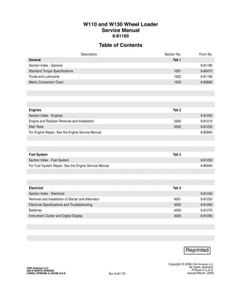
  • 1. Copyright © 2006 CNH America LLC. All rights reserved. Printed in U.S.A. Issued March, 2006 CNH America LLC. 245 E NORTH AVENUE CAROL STREAM, IL 60188 U.S.A. Bur 6-81170 W110 and W130 Wheel Loader Service Manual 6-81160 Table of Contents Description Section No. Form No. General Tab 1 Section Index - General 6-81180 Standard Torque Specifications 1001 6-80470 Fluids and Lubricants 1002 6-81190 Metric Conversion Chart 1003 6-80690 Engines Tab 2 Section Index - Engines 6-81200 Engine and Radiator Removal and Installation 2000 6-81210 Stall Tests 2002 6-81220 For Engine Repair, See the Engine Service Manual 6-80940 Fuel System Tab 3 Section Index - Fuel System 6-81230 For Fuel System Repair, See the Engine Service Manual 6-80940 Electrical Tab 4 Section Index - Electrical 6-81240 Removal and Installation of Starter and Alternator 4001 6-81250 Electrical Specifications and Troubleshooting 4002 6-81260 Batteries 4003 6-81270 Instrument Cluster and Digital Display 4005 6-81280
  • 2. Bur 6-81170 Issued 3-06 Printed in U.S.A. Steering Tab 5 Section Index - Steering 6-81290 Removal and Installation of Steering Components 5001 6-81300 Steering Specifications, Pressure Checks, and Troubleshooting 5002 6-81310 Steering Control Valve 5003 6-81320 Auxiliary Steering Priority Valve 5004 6-81330 Steering Cylinders 5005 6-81340 Center Pivot 5006 6-81350 Auxiliary Steering Motor and Pump 5007 6-81360 Power Train Tab 6 Section Index - Power Train 6-81370 Removal and Installation of Power Train Components 6001 6-81380 Transmission Specifications, Pressure Checks, and Troubleshooting 6002 6-81390 Transmission 6003 6-81400 Front Axle 6004 6-81410 Rear Axle 6004 6-81420 Drive Shafts, Center Bearing, and Universal Joints 6005 6-81430 Wheels and Tires 6006 6-81440 Transmission Control Valve 6007 6-81450 Brakes Tab 7 Section Index - Brakes 6-81460 Removal and Installation of Brake Components 7001 6-81470 Hydraulic Brake Troubleshooting 7002 6-81480 Brake Accumulators 7004 6-81490 Parking Brake 7008 6-81500 Hydraulics Tab 8 Section Index - Hydraulics 6-81510 Removal and Installation of Hydraulic Components 8001 6-81520 Hydraulic Specifications, Troubleshooting, and Pressure Checks 8002 6-81530 Cleaning the Hydraulic System 8003 6-81540 Loader Control Valve 8005 6-81550 Cylinders 8006 6-81560 Coupler Solenoid Locking Valve 8007 6-81570 Pilot Pressure Accumulator and Ride Control Accumulator 8013 6-81580 Ride Control Valve 8014 6-81590 W110 and W130 Wheel Loader Service Manual 6-81160 Table of Contents Description Section No. Form No.
  • 3. Copyright © 2006 CNH America LLC. All rights reserved. Printed in U.S.A. Issued March, 2006 CNH America LLC. 245 E NORTH AVENUE CAROL STREAM, IL 60188 U.S.A. Bur 6-81170 NOTE: CNH America LLC reserves the right to make improvements in design or changes in specifications at any time without incurring any obligation to install them on units previously sold. Mounted Equipment Tab 9 Section Index - Mounted Equipment 6-81600 Pedal and Levers 9001 6-81610 Air Conditioning Troubleshooting and System Checks For Systems with HFC-134a Refrigerant 9002 6-81620 Air Conditioner System Service 9003 6-81630 Removal and Installation of Air Conditioning and Heater Components 9004 6-81640 Loader 9006 6-81650 ROPS Cab and ROPS Canopy 9007 6-81660 Cab Glass Installation 9010 6-81670 Electrical Schematic Foldouts and Hydraulic Schematic Foldouts In Rear Pocket 6-81680 W110 and W130 Wheel Loader Service Manual 6-81160 Table of Contents Description Section No. Form No.
  • 4. Copyright © 2006 CNH America LLC. All rights reserved. Printed in U.S.A. Issued March, 2006 CNH America LLC. 245 E NORTH AVENUE CAROL STREAM, IL 60188 U.S.A. Bur 6-81180 SECTION INDEX GENERAL Standard Torque Specifications. . . . . . . . . . . . . . . . . . . . . . . . . . . . . . . . . . . . . . . . . . . . . . . . . . . . . . . . . . . . . .1001 Fluids and Lubricants . . . . . . . . . . . . . . . . . . . . . . . . . . . . . . . . . . . . . . . . . . . . . . . . . . . . . . . . . . . . . . . . . . . . .1002 Metric Conversion Chart . . . . . . . . . . . . . . . . . . . . . . . . . . . . . . . . . . . . . . . . . . . . . . . . . . . . . . . . . . . . . . . . . . .1003 Section Title Section Number
  • 5. Section 1001 1001 Copyright © 2006 CNH America LLC. All rights reserved. Printed in U.S.A. Issued January, 2006 CNH America LLC. 245 E NORTH AVENUE CAROL STREAM, IL 60188 U.S.A. Bur 6-80470 GENERAL TORQUE SPECIFICATIONS
  • 6. 1001-3 Bur 6-80470 Issued 1-06 Printed in U.S.A. TORQUE SPECIFICATIONS - DECIMAL HARDWARE Use the torques in this chart when special torques are not given. These torques apply to fasteners with both UNC and UNF threads as received from suppliers dry, or when lubricated with engine oil. Not applicable if special graphities, Molydisulfide greases, or other extreme pressure lubricants are used. Grade 5 Bolts, Nuts, and Studs Size Pound- Inches Newton metres 1/4 inch 108 to 132 12 to 15 5/16 inch 204 to 252 23 to 28 3/8 inch 420 to 504 48 to 57 Size Pound- Feet Newton metres 7/16 inch 54 to 64 73 to 87 1/2 inch 80 to 96 109 to 130 9/16 inch 110 to 132 149 to 179 5/8 inch 150 to 180 203 to 244 3/4 inch 270 to 324 366 to 439 7/8 inch 400 to 480 542 to 651 1.0 inch 580 to 696 787 to 944 1-1/8 inch 800 to 880 1085 to 1193 1-1/4 inch 1120 to 1240 1519 to 1681 1-3/8 inch 1460 to 1680 1980 to 2278 1-1/2 inch 1940 to 2200 2631 to 2983 Grade 8 Bolts, Nuts, and Studs Size Pound- Inches Newton metres 1/4 inch 144 to 180 16 to 20 5/16 inch 288 to 348 33 to 39 3/8 inch 540 to 648 61 to 73 Size Pound- Feet Newton metres 7/16 inch 70 to 84 95 to 114 1/2 inch 110 to 132 149 to 179 9/16 inch 160 to 192 217 to 260 5/8 inch 220 to 264 298 to 358 3/4 inch 380 to 456 515 to 618 7/8 inch 600 to 720 814 to 976 1.0 inch 900 to 1080 1220 to 1465 1-1/8 inch 1280 to 1440 1736 to 1953 1-1/4 inch 1820 to 2000 2468 to 2712 1-3/8 inch 2380 to 2720 3227 to 3688 1-1/2 inch 3160 to 3560 4285 to 4827 NOTE: Use thick nuts with Grade 8 bolts.
  • 7. 1001-4 Bur 6-80470 Issued 1-06 Printed in U.S.A. TORQUE SPECIFICATIONS - METRIC HARDWARE Use the following torques when specifications are not given. These values apply to fasteners with coarse threads as received from supplier, plated or unplated, or when lubricated with engine oil. These values do not apply if graphite or Molydisulfide grease or oil is used. Grade 12.9 Bolts, Nuts, and Studs Usually the torque values specified for grade 10.9 fasteners can be used satisfactorily on grade 12.9 fasteners. Grade 8.8 Bolts, Nuts, and Studs Size Pound- Inches Newton metres M4 24 to 36 3 to 4 M5 60 to 72 7 to 8 M6 96 to 108 11 to 12 M8 228 to 276 26 to 31 M10 456 to 540 52 to 61 Size Pound- Feet Newton metres M12 66 to 79 90 to 107 M14 106 to 127 144 to 172 M16 160 to 200 217 to 271 M20 320 to 380 434 to 515 M24 500 to 600 675 to 815 M30 920 to 1100 1250 to 1500 M36 1600 to 1950 2175 to 2600 8.8 Grade 10.9 Bolts, Nuts, and Studs Size Pound- Inches Newton metres M4 36 to 48 4 to 5 M5 84 to 96 9 to 11 M6 132 to 156 15 to 18 M8 324 to 384 37 to 43 Size Pound- Feet Newton metres M10 54 to 64 73 to 87 M12 93 to 112 125 to 150 M14 149 to 179 200 to 245 M16 230 to 280 310 to 380 M20 450 to 540 610 to 730 M24 780 to 940 1050 to 1275 M30 1470 to 1770 2000 to 2400 M36 2580 to 3090 3500 to 4200 10.9 12.9
  • 8. 1001-5 Bur 6-80470 Issued 1-06 Printed in U.S.A. TORQUE SPECIFICATIONS - STEEL HYDRAULIC FITTINGS 37 Degree Flare Fitting Tube OD Hose ID Thread Size Pound- Inches Newton metres 1/4 inch 6.4 mm 7/16-20 72 to 144 8 to 16 5/16 inch 7.9 mm 1/2-20 96 to 192 11 to 22 3/8 inch 9.5 mm 9/16-18 120 to 300 14 to 34 1/2 inch 12.7 mm 3/4-16 180 to 504 20 to 57 5/8 inch 15.9 mm 7/8-14 300 to 696 34 to 79 Tube OD Hose ID Thread Size Pound- Feet Newton metres 3/4 inch 19.0 mm 1-1/16-12 40 to 80 54 to 108 7/8 inch 22.2 mm 1-3/16-12 60 to 100 81 to 135 1.0 inch 25.4 mm 1-5/16-12 75 to 117 102 to 158 1-1/4 inch 31.8 mm 1-5/8-12 125 to 165 169 to 223 1-1/2 inch 38.1 mm 1-7/8-12 210 to 250 285 to 338 Split Flange Mounting Bolts Size Pound- Inches Newton metres 5/16-18 180 to 240 20 to 27 3/8-16 240 to 300 27 to 34 7/16-14 420 to 540 47 to 61 Size Pound- Feet Newton metres 1/2-13 55 to 65 74 to 88 5/8-11 140 to 150 190 to 203 Straight Threads with O-ring Tube OD Hose ID Thread Size Pound- Inches Newton metres 1/4 inch 6.4 mm 7/16-20 144 to 228 16 to 26 5/16 inch 7.9 mm 1/2-20 192 to 300 22 to 34 3/8 inch 9.5 mm 9/16-18 300 to 480 34 to 54 1/2 inch 12.7 mm 3/4-16 540 to 804 57 to 91 Tube OD Hose ID Thread Size Pound- Feet Newton metres 5/8 inch 15.9 mm 7/8-14 58 to 92 79 to 124 3/4 inch 19.0 mm 1-1/16-12 80 to 128 108 to 174 7/8 inch 22.2 mm 1-3/16-12 100 to 160 136 to 216 1.0 inch 25.4 mm 1-5/16-12 117 to 187 159 to 253 1-1/4 inch 31.8 mm 1-5/8-12 165 to 264 224 to 357 1-1/2 inch 38.1 mm 1-7/8-12 250 to 400 339 to 542
  • 9. Section 2000 2000 Copyright © 2006 CNH America LLC. All rights reserved. Printed in U.S.A. Issued March, 2006 CNH America LLC. 245 E NORTH AVENUE CAROL STREAM, IL 60188 U.S.A. Bur 6-81210 ENGINE AND RADIATOR REMOVAL AND INSTALLATION
  • 10. 2000-3 Bur 6-81210 Issued 3-06 Printed in U.S.A. ENGINE Removal STEP 1 Park machine on a level surface and lower bucket to floor. Stop engine. Actuate brake pedal several times to discharge brake accumulators. Move loader control lever back and forth at least 30 times to release any pressure from hydraulic circuit. STEP 2 BD00M030 Put articulation lock in LOCKED position. STEP 3 Slowly loosen the filler cap for hydraulic reservoir to release air pressure in hydraulic reservoir. STEP 4 Put master disconnect switch in OFF position. STEP 5 Disconnect battery cable from LH battery negative post. Put a plastic cap over the negative post. STEP 6 Disconnect battery cable from RH battery positive post. Put a plastic cap over the positive post. STEP 7 BD03J111 Open the engine compartment side panel, attach a lifting eye to the hole in the lower portion of the panel. STEP 8 BD03J110 Attach lifting straps to the hinge side of the hood, attach suitable lifting equipment to the straps and take up slack in the straps. STEP 9 BD03J112 Disconnect the gas cylinders from the side panel and hood. Remove hinge pins, remove panel from machine.
  • 11. 2000-4 Bur 6-81210 Issued 3-06 Printed in U.S.A. STEP 10 Repeat steps 7 through 9 for the other side panel. STEP 11 Attach lifting straps to the center hood section. STEP 12 Connect lifting equipment to the lifting straps. Take up all slack in strap connected to hood. STEP 13 BD03J115 Remove two nuts and bolts and four washers securing the rear of the hood. STEP 14 BD03J116 Remove the two front bolts and washers securing the front of the hood. STEP 15 Carefully raise and remove hood from loader. Lower hood onto suitable platform and disconnect lifting equipment. STEP 16 BC03J056 Remove the four rear grill mounting bolts, remove the grill. Remove the six rear grill frame mounting bolts and nuts, remove the frame. STEP 17 BD03J103 Tag and disconnect engine wiring harness connector from air filter restriction switch.
  • 12. 2000-5 Bur 6-81210 Issued 3-06 Printed in U.S.A. STEP 18 BS02J036 Loosen clamp (1) on air cleaner intake hose (2) and remove intake hose. STEP 19 Loosen clamps (3 and 5) on crankcase hose (6) and turbocharger intake hose (8). Disconnect hose (6) from breather pipe. Disconnect hose (8) with tube (7) attached from turbocharger. STEP 20 Support air cleaner assembly (12) and remove two lock nuts (9), bolts (11), four washers (10). Remove air cleaner (12) and associated parts as an assembly. STEP 21 BC03J132 Remove four bolts (1) and washers (2) securing drive belt guard (3) to the frame. 1. CLAMP 7. TUBE 2. INTAKE HOSE 8. HOSE 3. CLAMP 9. LOCK NUT 4. HOSE 10. WASHER 5. CLAMP 11. BOLT 6. HOSE 12. AIR CLEANER 2 1 19 3 5 6 5 7 1 12 3 10 9 11 10 8 1. BOLT 2. WASHER 3. DRIVE BELT GUARD 3 1 2 2 1
  • 13. 2000-6 Bur 6-81210 Issued 3-06 Printed in U.S.A. STEP 22 BC03J131 Remove clamp (1) securing exhaust tube elbow (10) to muffler (8). STEP 23 At front of engine, remove two bolts (2) and washers (3) securing muffler front mounting bracket (6). STEP 24 Support muffler (8) and brackets (6 and 7) and remove two bolts (4) and washers (5) at rear of engine. Remove muffler and brackets as an assembly from engine. STEP 25 Loosen clamp (9) and remove exhaust tube elbow (10) from turbocharger. STEP 26 BS02J048 Loosen two clamps (1). Remove tube (2) and hose (3) as an assembly. STEP 27 Loosen two clamps (5). Remove tube (6) and hose (7) as an assembly. STEP 28 BD03J096 Disconnect grounding strap from left side of engine. 1. CLAMP 6. FRONT BRACKET 2. BOLT 7. REAR BRACKET 3. WASHER 8. MUFFLER 4. BOLT 9. CLAMP 5. WASHER 10. EXHAUST TUBE ELBOW 8 6 2 9 10 1 8 7 4 3 5 1. CLAMP 5. CLAMP 2. TUBE 6. TUBE 3. HOSE 7. HOSE 4. CLAMP 8. CLAMP 8 7 6 5 2 3 4 1 5 1
  • 14. 2000-7 Bur 6-81210 Issued 3-06 Printed in U.S.A. STEP 29 BS02J056 Remove acorn nut (1), nut (2), and washer (3) securing cover (4) to starter. Remove cover. STEP 30 Remove nut and washer securing cables to starter B+ stud (5). Identify, tag, and disconnect both cables. STEP 31 BS02J055 Identify and tag rear chassis harness wire connected to starter solenoid terminal. Disconnect rear chassis harness wire from terminal. STEP 32 BD03J098 Identify, tag, and disconnect engine harness from alternator. STEP 33 Identify, tag, and disconnect connector from engine coolant temperature sender. Remove bolt and washer securing cable clamp to engine. STEP 34 If wheel loader is equipped with air conditioning, identify, tag, and disconnect connector from air conditioner compressor clutch. Identify. tag, and disconnect connector from air conditioning high pressure switch. STEP 35 Support air conditioning compressor and remove bolts securing compressor. Remove compressor and place on battery cover. 1. ACORN NUT 4. COVER 2. NUT 5. B+ STUD 3. WASHER 5 4 3 2 1
  • 15. 2000-8 Bur 6-81210 Issued 3-06 Printed in U.S.A. STEP 36 BD03J144 Remove bolts and bracket securing fuel line to rear of engine. STEP 37 BD03J145 Remove bolts, nuts and clamps securing wiring harness to rear of engine. STEP 38 If equipped, identify, tag, and disconnect wire from grid heater. STEP 39 If equipped, identify, tag, and disconnect connector from fuel filter heater. STEP 40 If equipped, identify, tag, and disconnect connector from fuel filter temperature switch. STEP 41 BD03J089 Disconnect injection pump fuel solenoid and oil pressure sending unit. STEP 42 BD03J090 STEP 43 Connect a vacuum pump to hydraulic reservoir. If a vacuum pump is not available, drain the hydraulic oil (hydraulic reservoir holds 68.5 liters (18 gallons) of oil). Turn on vacuum pump (if available). Tag, disconnect, and plug hoses connected to brake pump. Plug hoses securely and cap fittings. Turn off vacuum pump.
  • 16. 2000-9 Bur 6-81210 Issued 3-06 Printed in U.S.A. STEP 44 BD03J142 Remove bracket mounting hydraulic brake pump lines and fuel line from bell housing. STEP 45 BD00M031 Put a 37.8 liter (10 gallon) container below radiator drain. Remove cap and drain coolant into container. Install cap after coolant has drained. STEP 46 BS02J069 Loosen two clamps. Disconnect and remove bottom hose. STEP 47 BS02J068 Loosen two clamps (1) securing bleed line hose (2). Disconnect bleed line hose (2) from fittings. 1. CLAMP 5. HOSE 2. BLEED LINE HOSE 6. PIPE 3. CLAMP 7. TIE STRAP 4. CLAMP 8. HOSE 3 1 6 2 8 1 4 5 4 7 7
  • 17. 2000-10 Bur 6-81210 Issued 3-06 Printed in U.S.A. STEP 48 Loosen clamps (3 and 4). Disconnect and remove hose (5) from engine and pipe (6). Disconnect and remove pipe (6) with bleed line hose (2) attached from hose (8). If necessary, cut, remove, and discard tie straps (7) to separate bleed line hose (2) from pipe (6). STEP 49 BD00M031 Put a 18.9 liter (5 gallon) container below engine oil drain. Remove cap and drain engine oil into container. Install cap after oil has drained. STEP 50 BS02J065 Disconnect hose from elbow installed in engine oil pan. Put a plug in hose and a cap on fitting. STEP 51 BS02J070 Remove nut (1) and washer (2) securing ball joint (3) to throttle lever (4). STEP 52 Remove two nuts (5) and washers (6), U-bolt (7), and clamp (8) securing throttle cable (9) to support bracket (10). Position throttle cable away from engine. STEP 53 BS02J072 1. NUT 6. WASHER 2. WASHER 7. U-BOLT 3. BALL JOINT 8. CLAMP 4. THROTTLE LEVER 9. THROTTLE CABLE 5. NUT 10. SUPPORT BRACKET 1. BOLT 3. FUEL SUPPLY HOSE 2. CLAMP 4. FUEL RETURN HOSE 10 3 2 1 5 6 8 4 7 9 1 2 3 4
  • 18. 2000-11 Bur 6-81210 Issued 3-06 Printed in U.S.A. Remove bolt (1) and washer securing clamp (2) holding in-line fuel filter to engine block. Tag and disconnect fuel supply hose (3) from priming pump. Plug hose and cap fitting. Tag and disconnect fuel return hose (4) from fuel injection pump. Plug hose and cap fitting. STEP 54 BD01D200 At front of engine, remove six bolts securing drive shaft to engine coupling. Use a pry bar to move drive shaft away from engine coupling. STEP 55 Connect lifting equipment to engine lifting brackets. Take up all slack in lifting equipment. STEP 56 BS02J073 Remove nut (1), washer (2), bolt (3), and washer (4) securing engine and mounting brackets to chassis. STEP 57 Slowly raise engine from rear chassis. Check and be sure all harness connections, hoses, and throttle cable have been disconnected and are positioned out of the way. Remove engine from machine. 1. NUT 6. ENGINE MOUNT 2. WASHER 7. BOLT 3. BOLT 8. WASHER 4. WASHER 9. MOUNTING BRACKET 5. WASHER 3 4 6 9 8 7 6 2 1 5
  • 19. 2000-12 Bur 6-81210 Issued 3-06 Printed in U.S.A. Installation STEP 58 BS02J073 If engine mounting brackets (9) were removed, position bracket on engine and secure using bolts (7) and washers (8). Torque bolts to 118 to 130 Nm (87 to 98 pound-feet). If necessary, install new engine mount (6) in mounting bracket. Repeat this step to install remaining engine mounting brackets and engine mounts as necessary. STEP 59 Connect suitable lifting equipment to engine lifting brackets. Slowly raise engine and move into position over rear chassis. Be sure all harness connections and hoses are out of the way then lower engine. Put washer (5) between front engine mount (6) and chassis. Install washers (4 and 5), bolt (3), washer (2), and nut (1) in engine front mounts. Lower engine into position. STEP 60 Torque bolts (3) to a torque of 244 to 298 Nm (180 to 220 pound-feet). STEP 61 Disconnect lifting equipment from engine lifting brackets. STEP 62 BD01D200 At front of engine, position drive shaft on engine coupling. Put Loctite 242 on threads of six bolts. Install six bolts and tighten to a torque of 53 to 62 Nm (39 to 46 pound-feet). STEP 63 BD03J142 Install bracket mounting hydraulic brake pump lines and fuel line to bell housing. STEP 64 Turn on vacuum pump connected to hydraulic reservoir. Remove caps from brake pump fittings and plugs from brake pump hoses. Connect hoses to brake pump following tags installed during removal. Remove and discard tags. Turn off and disconnect vacuum pump from hydraulic reservoir. 1. NUT 6. ENGINE MOUNT 2. WASHER 7. BOLT 3. BOLT 8. WASHER 4. WASHER 9. MOUNTING BRACKET 5. WASHER 3 4 6 9 8 7 6 2 1 5 141 140
  • 20. 2000-13 Bur 6-81210 Issued 3-06 Printed in U.S.A. STEP 65 BS02J072 Remove plug from fuel return hose (4) and cap from fuel injection pump fitting. Connect fuel return hose to fuel injection pump. Remove plug from fuel supply hose (3) and cap from priming pump fitting. Connect fuel supply hose to priming pump. Position clamp (2) holding in-line fuel filter and secure to engine block using washer and bolt (1). STEP 66 BS02J070 Route throttle cable (9) up and over towards fuel injection pump. Put clamp (8), throttle cable (9), and U-bolt (7) on support bracket (10) and secure using two washers (6) and nuts (5). STEP 67 Install ball joint (3) on throttle lever (4) and secure using washer (2) and nut (1). STEP 68 BS02J065 Remove plug from oil drain hose and cap from fitting installed in engine oil pan. Connect hose to fitting and tighten. 1. BOLT 3. FUEL SUPPLY HOSE 2. CLAMP 4. FUEL RETURN HOSE 1. NUT 6. WASHER 2. WASHER 7. U-BOLT 3. BALL JOINT 8. CLAMP 4. THROTTLE LEVER 9. THROTTLE CABLE 5. NUT 10. SUPPORT BRACKET 1 2 3 4 10 3 2 1 5 6 8 4 7 9
  • 21. Thank you very much for your reading. Please Click Here. Then Get COMPLETE MANUAL. NO WAITING NOTE: If there is no response to click on the link above, please download the PDF document first and then click on it.
  • 22. 2000-14 Bur 6-81210 Issued 3-06 Printed in U.S.A. STEP 69 BS02J068 Put clamp (3) on hose (8). Connect pipe (6) to hose (8). Position clamp (3) and tighten to a torque of 10.1 to 11.3 Nm (90 to 100 lb-inch). Put clamps (4) on hose (5). Connect hose (5) to pipe (6) and engine coolant outlet. Position clamps (4) and tighten to a torque of 10.1 to 11.3 Nm (90 to 100 lb-inch). STEP 70 Put hose clamps (1) on bleed line hose (2) and connect hose to fittings. Position clamps (1) and tighten to a torque of 10.1 to 11.3 Nm (90 to 100 lb-inch). Install three tie straps (7) to secure bleed line hose (2) to pipe (6). STEP 71 BS02J069 Put clamps on hose. Connect hose between bottom pipe and engine coolant inlet. Position clamps and tighten to a torque of 10.1 to 11.3 Nm (90 to 100 lb-inch). STEP 72 If equipped, position and support air conditioning compressor on mounting bracket. Secure using bolts washers. STEP 73 If wheel loader is equipped with air conditioning, connect connector to air conditioning compressor clutch following tag installed during removal. Connect connector to air conditioning high pressure switch following tag installed during removal. Remove and discard tags. STEP 74 Install drive belt, take up slack in drive belt and tighten bolts. 1. CLAMP 5. HOSE 2. BLEED LINE HOSE 6. PIPE 3. CLAMP 7. TIE STRAP 4. CLAMP 8. HOSE 3 1 6 2 8 1 4 5 4 7 7 105 105 106
  • 23. 2000-15 Bur 6-81210 Issued 3-06 Printed in U.S.A. STEP 75 BD03J089 Connect injection pump fuel solenoid and oil pressure sending unit. STEP 76 If equipped, connect connector to fuel filter temperature switch following tag installed during removal. Remove and discard tag. STEP 77 If equipped, connect connector to fuel filter heater following tag installed during removal. Remove and discard tag. STEP 78 If equipped, connect wire to grid heater following tag installed during removal. Remove and discard tag. STEP 79 Connect connector to engine coolant temperature sender following tag installed during removal. Remove and discard tag. STEP 80 BD03J145 Position clamp holding engine harness on flywheel housing cover. STEP 81 BD03J098 Connect wires to alternator. STEP 82 BS02J055 Connect harness wire to starter solenoid terminal following tag installed during removal. Remove and discard tag.
  • 24. 2000-16 Bur 6-81210 Issued 3-06 Printed in U.S.A. STEP 83 BS02J056 Connect cables to starter B+ stud (5) following tags installed during removal. Install nut and washer to secure cables. Remove and discard tags from cables. STEP 84 Put cover (4) on starter. Install washer (3), nut (2), and acorn nut (1) to secure cover (4). STEP 85 BD03J096 Connect grounding strap from left side of engine. STEP 86 BS02J048 Install tube (6) and hose (7) as an assembly. Tighten two clamps (5) to a torque of 10.1 to 11.3 Nm (90 to 100 lbs-inch). STEP 87 Install tube (2) and hose (3) as an assembly. Tighten two clamps (1) to a torque of 10.1 to 11.3 Nm (90 to 100 lbs-inch). 1. ACORN NUT 4. COVER 2. NUT 5. B+ STUD 3. WASHER 5 4 3 2 1 1. CLAMP 5. CLAMP 2. TUBE 6. TUBE 3. HOSE 7. HOSE 4. CLAMP 8. CLAMP 8 7 6 5 2 3 4 1 5 1
  • 25. 2000-17 Bur 6-81210 Issued 3-06 Printed in U.S.A. STEP 88 BC03J131 Put clamp (9) on exhaust tube elbow (10). Install exhaust tube elbow and clamp on turbocharger. Do not tighten clamp at this time. STEP 89 Install and support muffler (8) and brackets (6 and 7) on engine while connecting muffler to exhaust tube elbow (10). Install two washers (5) and bolts (4) finger tight. STEP 90 At front of engine, install two washers (3) and bolts (2) to secure muffler front mounting bracket (6). Tighten bolts (2) to a torque of 118 to 133 Nm (87 to 98 pound-feet). Tighten bolts (4) to a torque of 68 to 77 Nm (50 to 56 pound-feet). STEP 91 Install clamp (1). Tighten clamp (1) to a torque of 20 to 25 Nm (15 to 18 pound-feet). Tighten clamp (9) to a torque of 4.8 to 5.2 Nm (42.5 to 46 pound-feet). STEP 92 BC03J132 Position drive belt guard (3) and secure using four washers (2) and bolts (1) to the frame. 1. CLAMP 6. FRONT BRACKET 2. BOLT 7. REAR BRACKET 3. WASHER 8. MUFFLER 4. BOLT 9. CLAMP 5. WASHER 10. EXHAUST TUBE ELBOW 8 6 2 9 10 1 8 7 4 3 5 1. BOLT 2. WASHER 3. DRIVE BELT GUARD 3 1 2 2 1
  • 26. 2000-18 Bur 6-81210 Issued 3-06 Printed in U.S.A. STEP 93 BS02J036 Position air cleaner assembly (12) and support as an assembly. Secure using two washers (10), bolts (11) and lock nuts (9). STEP 94 Connect turbocharger intake hose (8) attached to tube (7) to turbocharger and crankcase hose (6) to breather pipe. Position clamps (3 and 5) and tighten. Tighten clamps (3) to a torque of 10.1 to 11.3 Nm (90 to 100 lb-inch). STEP 95 Connect air cleaner intake hose (2) between cooling frame and air cleaner inlet. Position clamp (1) and tighten to a torque of 3.6 to 4.5 Nm (32.4 to 39.6 lb-inch). STEP 96 Remove plastic cap installed over the positive post during removal. Connect battery cable to RH battery positive post. STEP 97 Remove plastic cap installed over the negative post during removal. Connect battery cable to LH battery negative post. STEP 98 BD03J103 Connect engine wiring harness connector to air filter restriction switch following tag installed during removal. Remove and discard tag. STEP 99 BC03J056 Install the frame and secure with six mounting bolts and nuts. Install the grill and secure with four mounting bolts. STEP 100 Carefully raise and position hood onto loader. 1. CLAMP 7. TUBE 2. INTAKE HOSE 8. HOSE 3. CLAMP 9. LOCK NUT 4. HOSE 10. WASHER 5. CLAMP 11. BOLT 6. HOSE 12. AIR CLEANER 2 1 4 3 5 6 5 7 1 12 3 10 9 11 10 8
  • 27. 2000-19 Bur 6-81210 Issued 3-06 Printed in U.S.A. STEP 101 BD03J116 Install the two front bolts and washers securing the front of the hood. STEP 102 BD03J115 Install two nuts and bolts and four washers securing the rear of the hood. STEP 103 Place engine compartment side panel into position. STEP 104 BD03J112 Install hinge pins, connect the gas cylinders to the side panel and hood. STEP 105 Repeat steps 103 and 104 for the other side panel. STEP 106 BD00M031 Check and make sure that drain caps are tight. STEP 107 Install a new oil filter on engine. Fill engine with 10.5 liters (11 quarts) of New Holland AMBRA engine oil (SAE 15W-40). STEP 108 If hydraulic reservoir was drained, fill reservoir with 68.5 liters (18 gallons) of New Holland AMBRA Hydrosystem 46 fluid. STEP 109 Fill engine coolant system with a solution of 50% Ethylene Glycol and 50% water. Cooling system capacity is 34.1 liters (9 gallons). Install the radiator cap. Fill the coolant reservoir up to the FULL mark on the reservoir. STEP 110 Put master disconnect switch in ON position. WARNING: Hot coolant can spray out if radiator cap is removed. To remove radiator cap: Let system cool, turn to first notch, then wait until all pressure is released. Scalding can result from fast removal of radiator cap. STEP 111 Start engine and run the engine at low idle. Run the engine at operating temperature for approximately five minutes to completely mix the Ethylene Glycol and water. When the coolant is at operating temperature, stop the engine. When engine has cooled, check the coolant level at the reservoir. STEP 112 Lower and close hood side panels. STEP 113 Put articulation lock in OPERATING position.