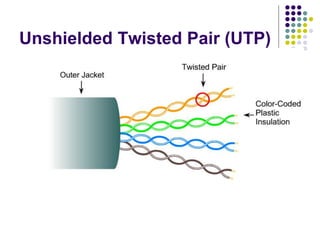
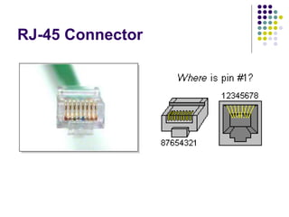
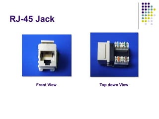
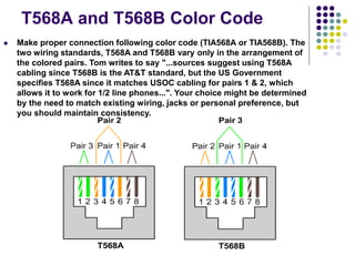
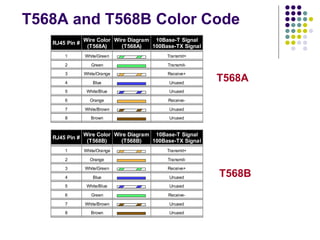
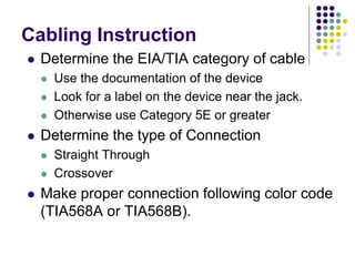
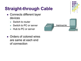
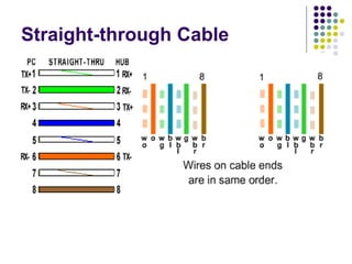
Cabling LAN
Imranul Hasan
Greenwich University, UK
Unshielded Twisted Pair (UTP)
RJ-45 Connector
RJ-45 Jack
Front View Top down View
T568A and T568B Color Code
 Make proper connection following color code (TIA568A or TIA568B). The
two wiring standards, T568A and T568B vary only in the arrangement of
the colored pairs. Tom writes to say "...sources suggest using T568A
cabling since T568B is the AT&T standard, but the US Government
specifies T568A since it matches USOC cabling for pairs 1 & 2, which
allows it to work for 1/2 line phones...". Your choice might be determined
by the need to match existing wiring, jacks or personal preference, but
you should maintain consistency.
T568A and T568B Color Code
RJ45 Pin #
Wire Color
(T568A)
Wire Diagram
(T568A)
10Base-T Signal
100Base-TX Signal
1 White/Green Transmit+
2 Green Transmit-
3 White/Orange Receive+
4 Blue Unused
5 White/Blue Unused
6 Orange Receive-
7 White/Brown Unused
8 Brown Unused
RJ45 Pin #
Wire Color
(T568B)
Wire Diagram
(T568B)
10Base-T Signal
100Base-TX Signal
1 White/Orange Transmit+
2 Orange Transmit-
3 White/Green Receive+
4 Blue Unused
5 White/Blue Unused
6 Green Receive-
7 White/Brown Unused
8 Brown Unused
T568A
T568B
Cabling Instruction
 Determine the EIA/TIA category of cable
 Use the documentation of the device
 Look for a label on the device near the jack.
 Otherwise use Category 5E or greater
 Determine the type of Connection
 Straight Through
 Crossover
 Make proper connection following color code
(TIA568A or TIA568B).
Straight-through Cable
 Connects different layer
devices
 Switch to router
 Switch to PC or server
 Hub to PC or server
 Orders of colored wires
are same at each end
of connection
Straight-through Cable
Crossover Cable
 Connects Similar
Devices
 Switch to switch
 Switch to hub
 Hub to hub
 Router to router
 PC to PC
 Router to PC
Crossover Cable (10Base-
T/100Base-TX)
Crossover Cable (1000Base-T)
RJ45 Pin #
(END 1)
Wire
Color
Diagram End
#1
RJ45 Pin #
(END 2)
Wire
Color
Diagram End
#2
1 White/Orange 1 White/Green
2 Orange 2 Green
3 White/Green 3 White/Orange
4 Blue 4 White/Brown
5 White/Blue 5 Brown
6 Green 6 Orange
7 White/Brown 7 Blue
8 Brown 8 White/Blue
Note: The cross over cable layout is suitable for 1000Base-T operation, all 4
pairs are crossed.
 Strip off about 2 inches of the cable sheath.
 Untwist the pairs - don't untwist them beyond what you have exposed, the
more untwisted cable you have the worse the problems you can run into.
 Align the colored wires according to the diagrams above.
 Trim all the wires to the same length, about 1/2" to 3/4" left exposed from the
sheath.
 Insert the wires into the RJ45 end - make sure each wire is fully inserted to the
front of the RJ45 end and in the correct order. The sheath of the cable should
extend into the RJ45 end by about 1/2" and will be held in place by the crimp.
 Crimp the RJ45 end with the crimper tool
 Verify the wires ended up the right order and that the wires extend to the front
of the RJ45 end and make good contact with the metal contacts in the RJ45
end.
 Cut the cable to length - make sure it is more than long enough for your needs.
Remember, an end to end connection should not extend more than 100m
(~328ft). Try to keep cables short, the longer the cable becomes the more it
may affect performance, usually noticable as a gradual decrease in speed and
increase in latency.
 Repeat the above steps for the second RJ45 end.
 If a cable tester is available, use it to verify the proper connectivity of the cable.
How to wire Ethernet Cables
Thank You!!

Network Cabling

  • 1.
  • 2.
  • 3.
  • 4.
    RJ-45 Jack Front ViewTop down View
  • 5.
    T568A and T568BColor Code  Make proper connection following color code (TIA568A or TIA568B). The two wiring standards, T568A and T568B vary only in the arrangement of the colored pairs. Tom writes to say "...sources suggest using T568A cabling since T568B is the AT&T standard, but the US Government specifies T568A since it matches USOC cabling for pairs 1 & 2, which allows it to work for 1/2 line phones...". Your choice might be determined by the need to match existing wiring, jacks or personal preference, but you should maintain consistency.
  • 6.
    T568A and T568BColor Code RJ45 Pin # Wire Color (T568A) Wire Diagram (T568A) 10Base-T Signal 100Base-TX Signal 1 White/Green Transmit+ 2 Green Transmit- 3 White/Orange Receive+ 4 Blue Unused 5 White/Blue Unused 6 Orange Receive- 7 White/Brown Unused 8 Brown Unused RJ45 Pin # Wire Color (T568B) Wire Diagram (T568B) 10Base-T Signal 100Base-TX Signal 1 White/Orange Transmit+ 2 Orange Transmit- 3 White/Green Receive+ 4 Blue Unused 5 White/Blue Unused 6 Green Receive- 7 White/Brown Unused 8 Brown Unused T568A T568B
  • 7.
    Cabling Instruction  Determinethe EIA/TIA category of cable  Use the documentation of the device  Look for a label on the device near the jack.  Otherwise use Category 5E or greater  Determine the type of Connection  Straight Through  Crossover  Make proper connection following color code (TIA568A or TIA568B).
  • 8.
    Straight-through Cable  Connectsdifferent layer devices  Switch to router  Switch to PC or server  Hub to PC or server  Orders of colored wires are same at each end of connection
  • 9.
  • 10.
    Crossover Cable  ConnectsSimilar Devices  Switch to switch  Switch to hub  Hub to hub  Router to router  PC to PC  Router to PC
  • 11.
  • 12.
    Crossover Cable (1000Base-T) RJ45Pin # (END 1) Wire Color Diagram End #1 RJ45 Pin # (END 2) Wire Color Diagram End #2 1 White/Orange 1 White/Green 2 Orange 2 Green 3 White/Green 3 White/Orange 4 Blue 4 White/Brown 5 White/Blue 5 Brown 6 Green 6 Orange 7 White/Brown 7 Blue 8 Brown 8 White/Blue Note: The cross over cable layout is suitable for 1000Base-T operation, all 4 pairs are crossed.
  • 13.
     Strip offabout 2 inches of the cable sheath.  Untwist the pairs - don't untwist them beyond what you have exposed, the more untwisted cable you have the worse the problems you can run into.  Align the colored wires according to the diagrams above.  Trim all the wires to the same length, about 1/2" to 3/4" left exposed from the sheath.  Insert the wires into the RJ45 end - make sure each wire is fully inserted to the front of the RJ45 end and in the correct order. The sheath of the cable should extend into the RJ45 end by about 1/2" and will be held in place by the crimp.  Crimp the RJ45 end with the crimper tool  Verify the wires ended up the right order and that the wires extend to the front of the RJ45 end and make good contact with the metal contacts in the RJ45 end.  Cut the cable to length - make sure it is more than long enough for your needs. Remember, an end to end connection should not extend more than 100m (~328ft). Try to keep cables short, the longer the cable becomes the more it may affect performance, usually noticable as a gradual decrease in speed and increase in latency.  Repeat the above steps for the second RJ45 end.  If a cable tester is available, use it to verify the proper connectivity of the cable. How to wire Ethernet Cables
  • 14.