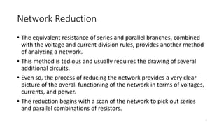
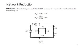
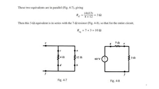
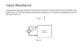
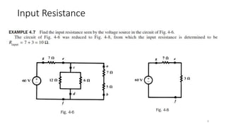
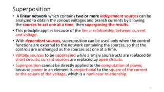
Network Analysis Techniques
Network Reduction
Input Resistance
Superposition
1
Network Reduction
• The equivalent resistance of series and parallel branches, combined
with the voltage and current division rules, provides another method
of analyzing a network.
• This method is tedious and usually requires the drawing of several
additional circuits.
• Even so, the process of reducing the network provides a very clear
picture of the overall functioning of the network in terms of voltages,
currents, and power.
• The reduction begins with a scan of the network to pick out series
and parallel combinations of resistors.
2
Network Reduction
3
4
5
6
Input Resistance
7
Input Resistance
8
Output Resistance
• A voltage source applied to a passive network results in voltages
between all nodes of the network.
• An external resistor connected between two nodes will draw current
from the network and in general will reduce the voltage between
those nodes.
• This is due to the voltage across the output resistance (see the
Thévenin equivalent circuit).
• The output resistance is found by dividing the open-circuited voltage
to the short-circuited current between the desired terminals.
9
Output Resistance
10
Superposition
• A linear network which contains two or more independent sources can be
analyzed to obtain the various voltages and branch currents by allowing
the sources to act one at a time, then superposing the results.
• This principle applies because of the linear relationship between current
and voltage.
• With dependent sources, superposition can be used only when the control
functions are external to the network containing the sources, so that the
controls are unchanged as the sources act one at a time.
• Voltage sources to be suppressed while a single source acts are replaced by
short circuits; current sources are replaced by open circuits.
• Superposition cannot be directly applied to the computation of power,
because power in an element is proportional to the square of the current
or the square of the voltage, which is a nonlinear relationship.
11
12
13

Network Analysis Techniques_NetworkReduction.pptx

  • 1.
    Network Analysis Techniques NetworkReduction Input Resistance Superposition 1
  • 2.
    Network Reduction • Theequivalent resistance of series and parallel branches, combined with the voltage and current division rules, provides another method of analyzing a network. • This method is tedious and usually requires the drawing of several additional circuits. • Even so, the process of reducing the network provides a very clear picture of the overall functioning of the network in terms of voltages, currents, and power. • The reduction begins with a scan of the network to pick out series and parallel combinations of resistors. 2
  • 3.
  • 4.
  • 5.
  • 6.
  • 7.
  • 8.
  • 9.
    Output Resistance • Avoltage source applied to a passive network results in voltages between all nodes of the network. • An external resistor connected between two nodes will draw current from the network and in general will reduce the voltage between those nodes. • This is due to the voltage across the output resistance (see the Thévenin equivalent circuit). • The output resistance is found by dividing the open-circuited voltage to the short-circuited current between the desired terminals. 9
  • 10.
  • 11.
    Superposition • A linearnetwork which contains two or more independent sources can be analyzed to obtain the various voltages and branch currents by allowing the sources to act one at a time, then superposing the results. • This principle applies because of the linear relationship between current and voltage. • With dependent sources, superposition can be used only when the control functions are external to the network containing the sources, so that the controls are unchanged as the sources act one at a time. • Voltage sources to be suppressed while a single source acts are replaced by short circuits; current sources are replaced by open circuits. • Superposition cannot be directly applied to the computation of power, because power in an element is proportional to the square of the current or the square of the voltage, which is a nonlinear relationship. 11
  • 12.
  • 13.