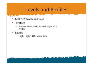
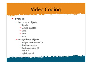
Levels and Profiles
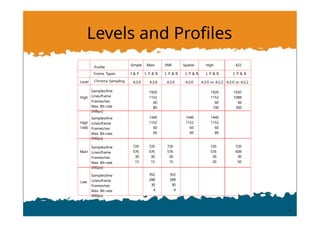
Profile
SimpleMain SNR Spatial High 422
Frame Types I & P I, P & B I, P & B I, P & B I, P & B I, P & B
Level Chroma Sampling 4:2:0 4:2:0 4:2:0 4:2:0 4:2:0 or 4:2:2 4:2:0 or 4:2:2
High
Samples/line
Lines/frame
Frames/sec
Max Bit-rate
(MBps)
1920
1152
60
80
1920
1152
60
100
1920
1088
60
300
High
1440
Samples/line
Lines/frame
Frames/sec
Max Bit-rate
(MBps)
1440
1152
60
60
1440
1152
60
60
1440
1152
60
80
Main
Samples/line
Lines/frame
Frames/sec
Max Bit-rate
(MBps)
720
576
30
15
720
576
30
15
720
576
30
15
720
576
30
20
720
608
30
50
Low
Samples/line
Lines/frame
Frames/sec
Max Bit-rate
(MBps)
352
288
30
4
352
288
30
4
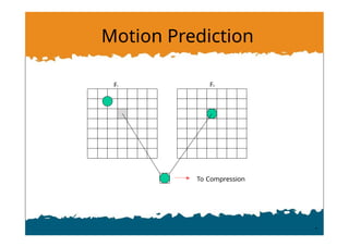
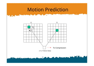
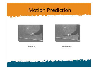
7.
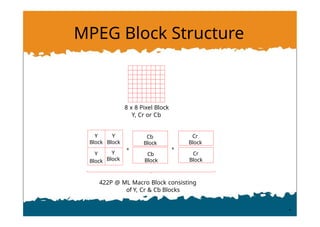
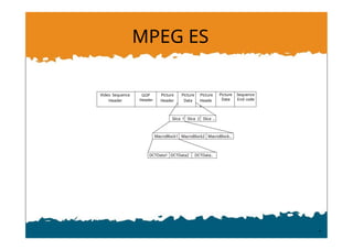
MPEG Block Structure
++
8 x 8 Pixel Block
Y, Cr or Cb
422P @ ML Macro Block consisting
of Y, Cr & Cb Blocks
Y
Block
Y
Block
Y
Block
Y
Block
Cb
Block
Cb
Block
Cr
Block
Cr
Block
8.
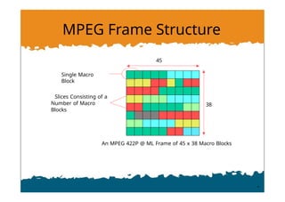
MPEG Frame Structure
AnMPEG 422P @ ML Frame of 45 x 38 Macro Blocks
Slices Consisting of a
Number of Macro
Blocks
Single Macro
Block
45
38
9.
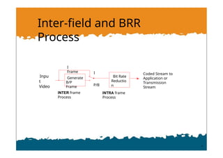
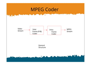
Inter-field and BRR
Process
CodedStream to
Application or
Transmission
Stream
INTRA frame
Process
INTER frame
Process
Inpu
t
Video
Generate
B/P
Frame
Bit Rate
Reductio
n
I
Frame I
P/B
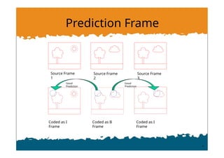
Frame Types
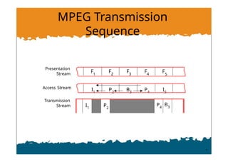
• IFrame
– Intra frame compression
• P Frame
– Forward Prediction frame
• Typically 30% Size of I frame
• B Frame
– Bi-directional Prediction
• May refer to I or P frames before or after the coding
frame
• Typically 50% the size of P frame (I.e 15% size of I
frame)
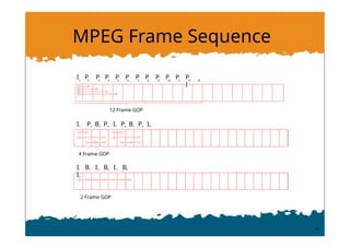
13.
MPEG Frame Sequence
I12 3 4
P P P 5
P 6
P 7
P 8
P 9
P 10
P 11
P 12
P
I
13
12 Frame GOP
I1 P2 B3 P4 I5 P6 B7 P8 I9
4 Frame GOP
I1 B2 I3 B4 I5 B6
I7
2 Frame GOP
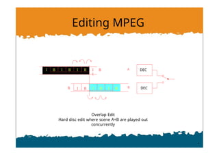
Editing MPEG
Overlap Edit
Harddisc edit where scene A+B are played out
concurrently
I
B
I
B
I B I B
I
I
B
I
B
I B
A
B
B
DEC
DEC
29.
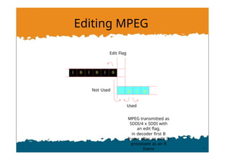
Editing MPEG
Edit Flag
Used
MPEGtransmitted as
SDDI/4 x SDDI with
an edit flag,
in decoder first B
frame after an edit is
processed as an R
frame
I B I B I B
Not Used I B I B
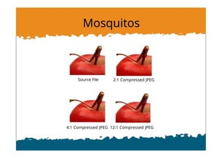
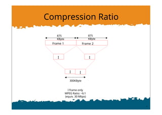
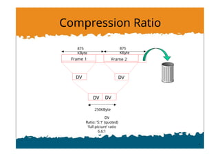
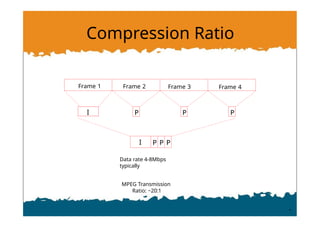
Compression Ratio
I PP P
I P P P
Data rate 4-8Mbps
typically
MPEG Transmission
Ratio: ~20:1
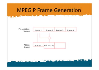
Frame 1 Frame 2 Frame 3 Frame 4
38.
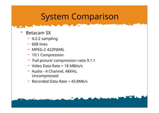
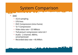
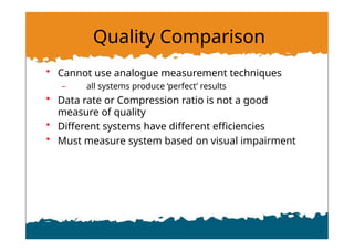
Quality Comparison
• Cannotuse analogue measurement techniques
– all systems produce ‘perfect’ results
• Data rate or Compression ratio is not a good
measure of quality
• Different systems have different efficiencies
• Must measure system based on visual impairment
39.
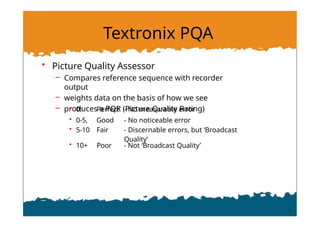
Textronix PQA
• PictureQuality Assessor
– Compares reference sequence with recorder
output
– weights data on the basis of how we see
– produces a PQR (Picture Quality Rating)
• 0: Perfect - No measurable error
• 0-5, Good - No noticeable error
• 5-10 Fair - Discernable errors, but ‘Broadcast
Quality’
• 10+ Poor - Not ‘Broadcast Quality’
40.
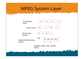
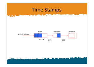
MPEG System Layer
Fr1
Fr 2
Fr 3
Fr 4
'Access Units'
'Elementary
Stream'
'Presentation
Units'
B 1 I 2 I 4
B 3
B 1
I 2
B 3
I 4
HD HD
Data Data
Variable Length <64k (Except
Video)
PES
Packetised Elementary
Stream
41.
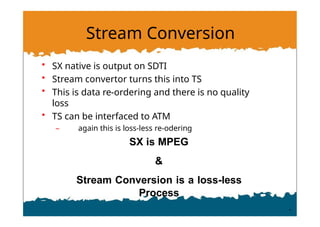
Stream Conversion
• SXnative is output on SDTI
• Stream convertor turns this into TS
• This is data re-ordering and there is no quality
loss
• TS can be interfaced to ATM
– again this is loss-less re-odering
SX is MPEG
&
Stream Conversion is a loss-less
Process
42.
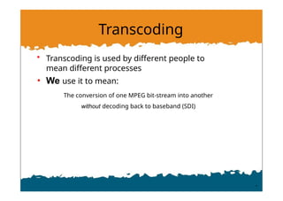
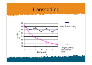
Transcoding
• Transcoding isused by different people to
mean different processes
• We use it to mean:
The conversion of one MPEG bit-stream into another
without decoding back to baseband (SDI)
43.
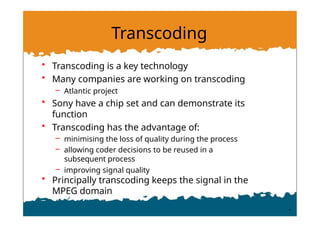
Transcoding
• Transcoding isa key technology
• Many companies are working on transcoding
– Atlantic project
• Sony have a chip set and can demonstrate its
function
• Transcoding has the advantage of:
– minimising the loss of quality during the process
– allowing coder decisions to be reused in a
subsequent process
– improving signal quality
• Principally transcoding keeps the signal in the
MPEG domain
44.
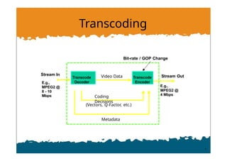
Transcoding
Stream In
E.g.,
MPEG2 @
8- 10
Mbps
E.g.,
MPEG2 @
4 Mbps
Transcode
Decoder
Video Data
Bit-rate / GOP Change
Coding
Decisions
Transcode
Encoder
Stream Out
(Vectors, Q-Factor, etc.)
Metadata
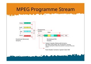
MPEG Programme Stream
Video
Audi
o
PacketisedElemental
Streams
Dat
a
M
U
X
Programme
Stream
PH SH PH SH
Multiplexed PES
Packets
System Header (Optional) Contains:
eg.*Max Data Rate, No of Streams Timing
*can be used by RX to determine whether to attempt to decode
stream
Pack Header Contains: System Clock Ref
Pack
Clock
49.
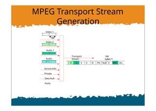
MPEG Transport Stream
Generation
ServiceInfo
Private
Data Null
Packs
Transport
Stream
V A V V SI PD Null V PMT etc.
188
bytes
Video 1
188
Video 2
Audio 1
Audio
2
50.
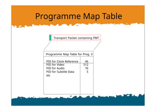
Programme Map Table
ProgrammeMap Table for Prog. 3
PID for Clock Reference 46
PID for Video 512
PID for Audio 76
PID for Subtitle Data 5
etc
Transport Packet containing PMT
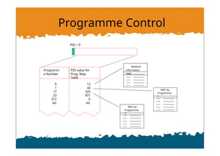
51.
Programme Control
PID =0
Programm
e Number
0
1
17
23
312
etc
12
43
325
871
6
etc
PID value for
Prog. Map
Table
Network
Information
Table
PMT for
Programme
1
PMT for
Programme
2
52.
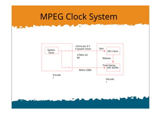
MPEG Clock System
System
Clock
DECClock
Encode
r
Sync
Decode
r
>Once per 0.7
S System Clock
27MHz 42
Bit Release
Time Stamp
DEC Buffer
90kHz 33Bit
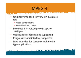
MPEG-4
• Originally intendedfor very low data rate
for:
– Video conferencing
– Portable video phones
• Low data limit raised (now 5Kbps to
10Mbps)
• Wide range of resolutions supported
• Progressive and interlace supported
• Now intended for complex multimedia
type applications
56.
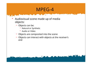
MPEG-4
• Audiovisual scenemade up of media
objects:
– Objects can be:
• Natural or Synthetic
• Audio or Video
– Objects are composited into the scene
– Objects can interact with objects at the receiver’s
end
57.
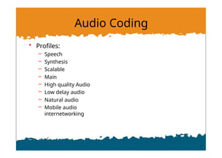
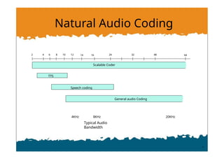
Audio Coding
• Profiles:
–Speech
– Synthesis
– Scalable
– Main
– High quality Audio
– Low delay audio
– Natural audio
– Mobile audio
internetworking
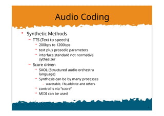
Audio Coding
• SyntheticMethods
– TTS (Text to speech)
• 200bps to 1200bps
• text plus prosodic parameters
• interface standard not normative
sythesizer
– Score driven
• SAOL (Structured audio orchestra
language)
• Synthesis can be by many processes
– wavetable, FM,additive and others
• control is via “score”
• MIDI can be used