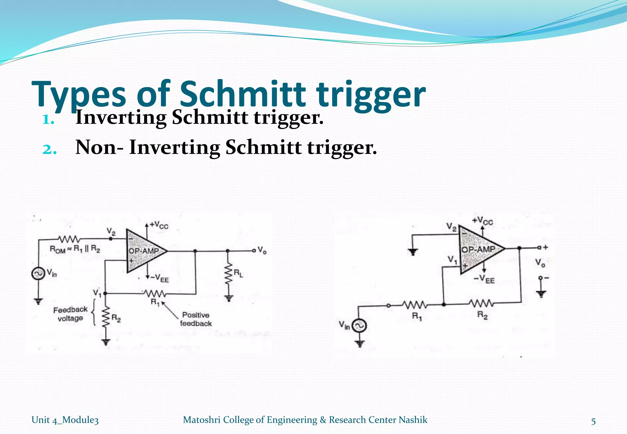
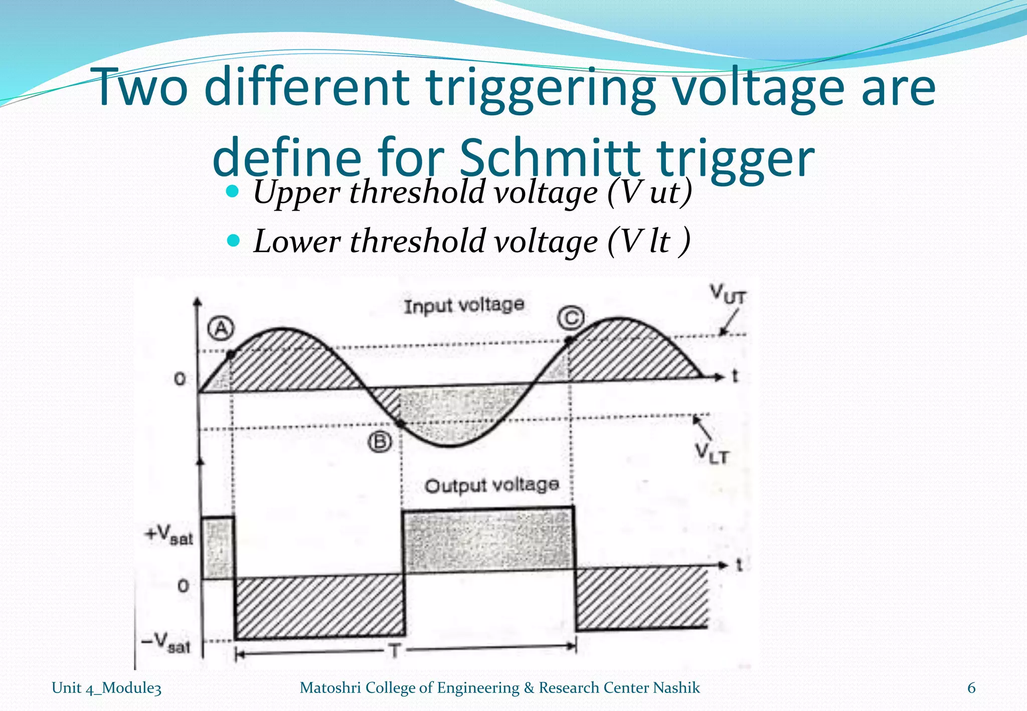
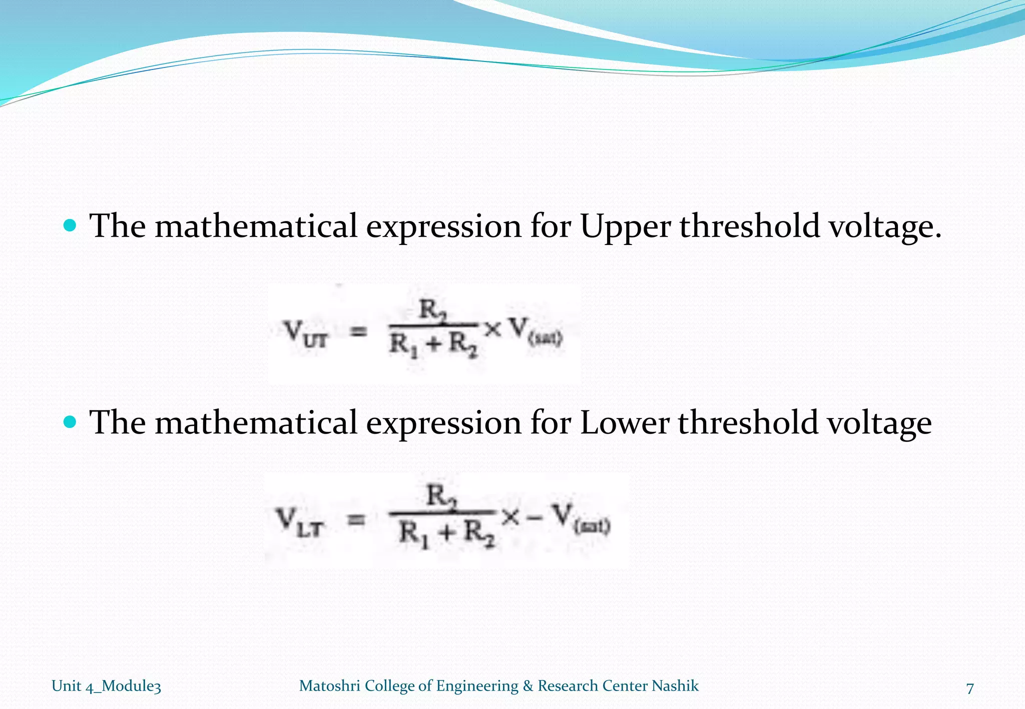
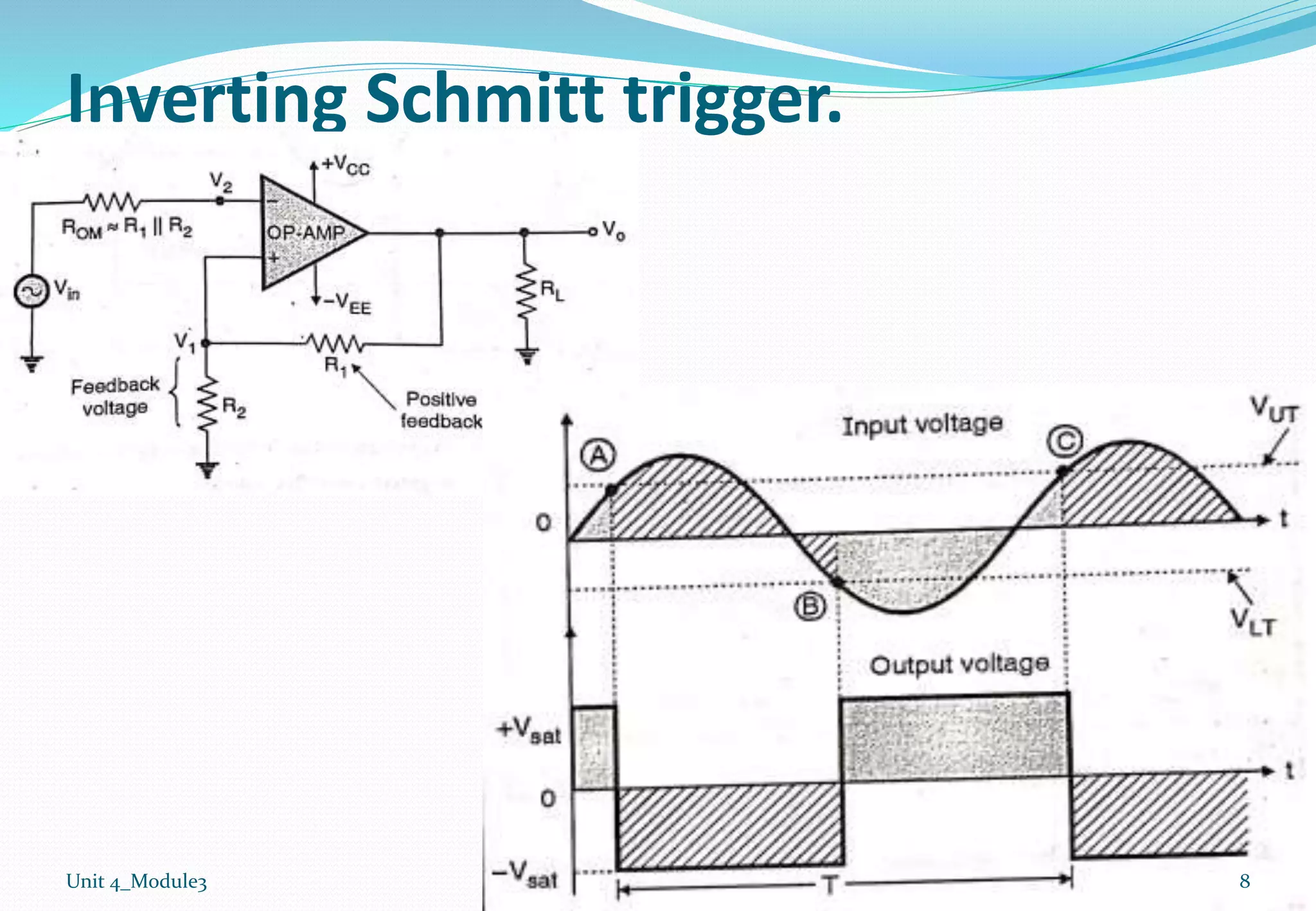
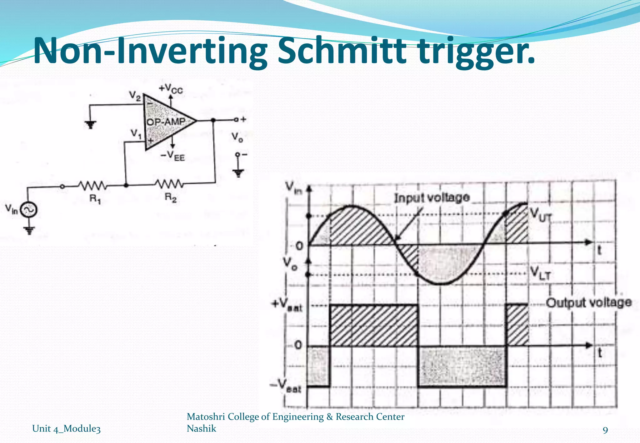
By
Mr. C.R.Shinde
Electrical Engineering Department
Matoshri College of Engineering & Research centre, Nashik
Unit 04: Operational Amplifier Applications.
Unit 4_Module3
1. Introduction to Op-Amp
2. Op-Amp as zero crossing detector (ZCD) and comparator.
3. Op-Amp as Schmitt trigger.
4. Op-Amp as V-I and I-V converters.
5. Op-Amp as Instrumentation amplifier.
6. Waveform generation using Op-Amp - sine, square, saw
tooth and triangular generator.
2
Matoshri College of Engineering & Research Center Nashik
Op-Amp as Schmitt trigger
Unit 4_Module3 3
Matoshri College of Engineering & Research Center Nashik
Schmitt trigger
 Schmitt trigger is basically a “comparator”.
 In comparator no feedback is being used.
 When comparator used positive feedback is known as
“Schmitt trigger”.
Unit 4_Module3 4
Matoshri College of Engineering & Research Center Nashik
Types of Schmitt trigger
1. Inverting Schmitt trigger.
2. Non- Inverting Schmitt trigger.
Unit 4_Module3 5
Matoshri College of Engineering & Research Center Nashik
Two different triggering voltage are
define for Schmitt trigger
 Upper threshold voltage (V ut)
 Lower threshold voltage (V lt )
Unit 4_Module3 6
Matoshri College of Engineering & Research Center Nashik
 The mathematical expression for Upper threshold voltage.
 The mathematical expression for Lower threshold voltage
Unit 4_Module3 7
Matoshri College of Engineering & Research Center Nashik
Inverting Schmitt trigger.
Unit 4_Module3 8
Non-Inverting Schmitt trigger.
Unit 4_Module3 9
Matoshri College of Engineering & Research Center
Nashik
PARAMETERS COMPARATOR SCHMITT TRIGGER
Use of feedback Feedback is not used Positive feedback is used
Trigger Level At zero volt or at the Vref. The upper and lower level
trigger have distinct values.
Output voltage The output voltage can be
+Vsat or –Vsat.
The output voltage can be
+Vsat or –Vsat.
Configurations Non-Inverting or Inverting
Comparator
Non- Inverting & Inverting
Schmiit trigger.
Application ZCD, Window Detector ,
Schmitt trigger
To convert any shape
waveform to square shape
Unit 4_Module3 Matoshri College of Engineering & Research Center Nashik 10
Thank you
Mr. C. R. Shinde
Electrical Engineering Department
Matoshri College of Engineering & Research centre, Nashik
If you have any query, ask me anytime on…… … .. . . .
cshinde58@gmail.com
chandrakant.shinde@matoshri.edu.in
9970031353
Unit 4_Module3 11
Matoshri College of Engineering & Research Center
Nashik

Module3: opamp as a Schmitt trigger

  • 1.
    By Mr. C.R.Shinde Electrical EngineeringDepartment Matoshri College of Engineering & Research centre, Nashik
  • 2.
    Unit 04: OperationalAmplifier Applications. Unit 4_Module3 1. Introduction to Op-Amp 2. Op-Amp as zero crossing detector (ZCD) and comparator. 3. Op-Amp as Schmitt trigger. 4. Op-Amp as V-I and I-V converters. 5. Op-Amp as Instrumentation amplifier. 6. Waveform generation using Op-Amp - sine, square, saw tooth and triangular generator. 2 Matoshri College of Engineering & Research Center Nashik
  • 3.
    Op-Amp as Schmitttrigger Unit 4_Module3 3 Matoshri College of Engineering & Research Center Nashik
  • 4.
    Schmitt trigger  Schmitttrigger is basically a “comparator”.  In comparator no feedback is being used.  When comparator used positive feedback is known as “Schmitt trigger”. Unit 4_Module3 4 Matoshri College of Engineering & Research Center Nashik
  • 5.
    Types of Schmitttrigger 1. Inverting Schmitt trigger. 2. Non- Inverting Schmitt trigger. Unit 4_Module3 5 Matoshri College of Engineering & Research Center Nashik
  • 6.
    Two different triggeringvoltage are define for Schmitt trigger  Upper threshold voltage (V ut)  Lower threshold voltage (V lt ) Unit 4_Module3 6 Matoshri College of Engineering & Research Center Nashik
  • 7.
     The mathematicalexpression for Upper threshold voltage.  The mathematical expression for Lower threshold voltage Unit 4_Module3 7 Matoshri College of Engineering & Research Center Nashik
  • 8.
  • 9.
    Non-Inverting Schmitt trigger. Unit4_Module3 9 Matoshri College of Engineering & Research Center Nashik
  • 10.
    PARAMETERS COMPARATOR SCHMITTTRIGGER Use of feedback Feedback is not used Positive feedback is used Trigger Level At zero volt or at the Vref. The upper and lower level trigger have distinct values. Output voltage The output voltage can be +Vsat or –Vsat. The output voltage can be +Vsat or –Vsat. Configurations Non-Inverting or Inverting Comparator Non- Inverting & Inverting Schmiit trigger. Application ZCD, Window Detector , Schmitt trigger To convert any shape waveform to square shape Unit 4_Module3 Matoshri College of Engineering & Research Center Nashik 10
  • 11.
    Thank you Mr. C.R. Shinde Electrical Engineering Department Matoshri College of Engineering & Research centre, Nashik If you have any query, ask me anytime on…… … .. . . . cshinde58@gmail.com chandrakant.shinde@matoshri.edu.in 9970031353 Unit 4_Module3 11 Matoshri College of Engineering & Research Center Nashik