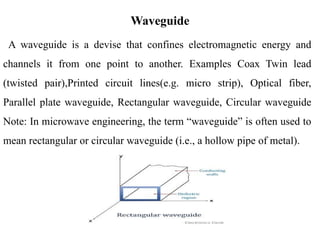
A waveguide isa devise that confines electromagnetic energy and
channels it from one point to another. Examples Coax Twin lead
(twisted pair),Printed circuit lines(e.g. micro strip), Optical fiber,
Parallel plate waveguide, Rectangular waveguide, Circular waveguide
Note: In microwave engineering, the term “waveguide” is often used to
mean rectangular or circular waveguide (i.e., a hollow pipe of metal).
Waveguide
3.
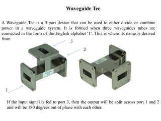
A Waveguide Teeis a 3-port device that can be used to either divide or combine
power in a waveguide system. It is formed when three waveguides tubes are
connected in the form of the English alphabet 'T'. This is where its name is derived
from.
If the input signal is fed to port 3, then the output will be split across port 1 and 2
and will be 180 degrees out of phase with each other.
Waveguide Tee
1
3
2
4.
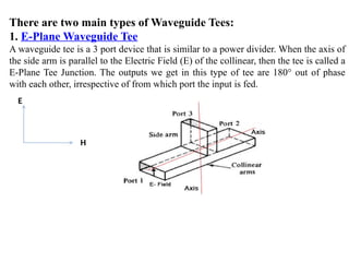
There are twomain types of Waveguide Tees:
1. E-Plane Waveguide Tee
A waveguide tee is a 3 port device that is similar to a power divider. When the axis of
the side arm is parallel to the Electric Field (E) of the collinear, then the tee is called a
E-Plane Tee Junction. The outputs we get in this type of tee are 180° out of phase
with each other, irrespective of from which port the input is fed.
E
H
5.
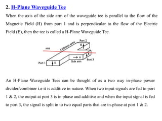
2. H-Plane WaveguideTee
When the axis of the side arm of the waveguide tee is parallel to the flow of the
Magnetic Field (H) from port 1 and is perpendicular to the flow of the Electric
Field (E), then the tee is called a H-Plane Waveguide Tee.
An H-Plane Waveguide Tees can be thought of as a two way in-phase power
divider/combiner i.e it is additive in nature. When two input signals are fed to port
1 & 2, the output at port 3 is in phase and additive and when the input signal is fed
to port 3, the signal is split in to two equal parts that are in-phase at port 1 & 2.
6.
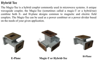
The Magic-Tee isa hybrid coupler commonly used in microwave systems. A unique
waveguide coupler, the Magic-Tee (sometimes called a magic-T or a hybrid-tee)
combine both E- and H-plane designs common to magnetic and electric field
couplers. The Magic-Tee can be used as a power combiner or a power divider based
on the needs of your given application.
Hybrid Tee
E-Plane
H-Plane
Magic-T or Hybrid-Tee
7.
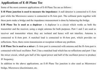
Applications of E-HPlane Tee
Some of the most common applications of E-H Plane Tee are as follows :
E-H Plane junction is used to measure the impedance: A null detector is connected to E-Arm
port while the Microwave source is connected to H-Arm port. The collinear ports together with
these ports make a bridge and the impedance measurement is done by balancing the bridge.
E-H Plane Tee is used as a duplexer : A duplexer is a circuit which works as both the
transmitter and the receiver, using a single antenna for both purposes. Port 1 and 2 are used as
receiver and transmitter where they are isolated and hence will not interfere. Antenna is
connected to E-Arm port. A matched load is connected to H-Arm port, which provides no
reflections. Now, there exists transmission or reception without any problem.
E-H Plane Tee is used as a mixer : E-Arm port is connected with antenna and the H-Arm port is
connected with local oscillator. Port 2 has a matched load which has no reflections and port 1 has
the mixer circuit, which gets half of the signal power and half of the oscillator power to produce
IF frequency.
In addition to the above applications, an E-H Plane Tee junction is also used as Microwave
bridge, Microwave discriminator, etc.
8.
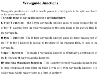
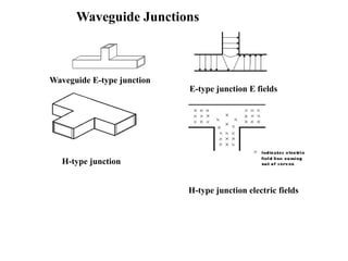
Waveguide Junctions
Waveguide junctionsare used to enable power in a waveguide to be split, combined
or for some extracted.
The main types of waveguide junction are listed below:
E-Type T Junction: The E-type waveguide junction gains its name because the top
of the "T" extends from the main waveguide in the same plane as the electric field in
the waveguide.
H-type T Junction: The H-type waveguide junction gains its name because top of
the "T" in the T junction is parallel to the plane of the magnetic field, H lines in the
waveguide.
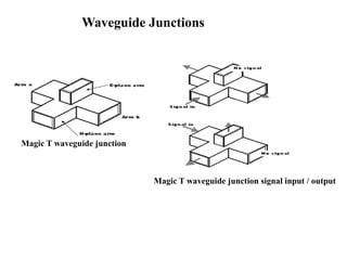
Magic T Junction: The magic T waveguide junction is effectively a combination of
the E-type and H-type waveguide junctions.
Hybrid Ring Waveguide Junction: This is another form of waveguide junction that
is more complicated than either the basic E-type or H-type waveguide junction. It is
widely used within radar system as a form of duplexer
Magic T waveguidejunction
Magic T waveguide junction signal input / output
Waveguide Junctions
11.
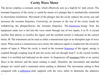
Cavity Wave Meter
Thedevice employs a resonant cavity, which effectively acts as a high-Q LC tank circuit. The
resonant frequency of the cavity is varied by means of a plunger that is mechanically connected
to micrometer mechanism. Movement of the plunger into the cavity reduces the cavity size and
increases the resonant frequency. Conversely, an increase in the size of the cavity (made by
withdrawing the plunger)lowers the resonant frequency. The microwave energy from the
equipment under test is fed into the wave meter through one of two inputs, A or D. A crystal
rectifier then detects or rectifies the signal, and the rectified current is indicated on the current
meter, M. The instrument can be used as either a transmission type or an absorption type of wave
meter. When used as a transmission wave meter, the unknown signal is coupled into the circuit by
means of input A. When the cavity is tuned to the resonant frequency of the signal, energy is
coupled through coupling loop B into the cavity and out through loop C to the crystal rectifier
where it is rectified and indicated on the meter. At frequencies off resonance little or no current
flows in the detector and the meter reading is small. Therefore, the micrometer and attached
plunger are varied until a maximum meter reading is obtained. The micrometer setting is then
compared with a calibration chart supplied with the wave meter to determine the unknown
12.
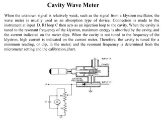
Cavity Wave Meter
Whenthe unknown signal is relatively weak, such as the signal from a klystron oscillator, the
wave meter is usually used as an absorption type of device. Connection is made to the
instrument at input D. Rf loop C then acts as an injection loop to the cavity. When the cavity is
tuned to the resonant frequency of the klystron, maximum energy is absorbed by the cavity, and
the current indicated on the meter dips. When the cavity is not tuned to the frequency of the
klystron, high current is indicated on the current meter. Therefore, the cavity is tuned for a
minimum reading, or dip, in the meter; and the resonant frequency is determined from the
micrometer setting and the calibration chart.
13.
Directional Couplers, Isolatorsand Circulators
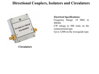
Waveguide circulators are devices with three ports developed to create isolation between
transmitted and received signals. These are commonly used for electronically steered antenna
(AESA) arrays, telecommunications applications, and satellite communications etc.
A waveguide isolator is a modified circulator having one port terminated with a matched
impedance. Both the devices are typically used for preventing high powered transmitter outputs
interfering with sensitive receiver circuitry. It efficiently does so by separating received signals at
the input of the antenna from the transmitter’s signals.
Most of the circulators that are based on passive ferromagnetic technologies are coaxial or
waveguide packaged devices. These types of circulators work best in their frequency range of
operation by providing very high isolation. As compared to cavity duplexers being used for in-
building telecommunications installations and base stations.
Both of these are used in the applications ranging from hundreds of megahertz to tens of
gigahertz, it makes them perfect for operations in radar and communication bands. Many factors
limit the frequency bandwidth of operation of a circulator like the geometry of the magnetic
material used, the impedance matching network of the circulator, and the design of the
transmission line along with manufacturing techniques and the types of ferrite.
The performance of waveguide circulators and isolators is measured on the parameters of
isolation, bandwidth, and insertion loss etc. Other important factors that should be considered are
power handling, size, interconnect technology, and temperature range.
14.
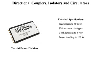
Coaxial Power Dividers
ElectricalSpecifications:
Frequencies to 40 GHz
Various connector types
Configurations to 8 way
Power handling to 100 W
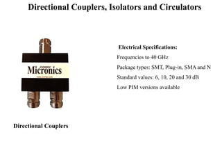
Directional Couplers, Isolators and Circulators
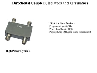
High Power Hybrids
ElectricalSpecifications:
Frequencies to 40 GHz
Power handling to 1KW
Package types: SMT, drop-in and connectorized
Directional Couplers, Isolators and Circulators
17.
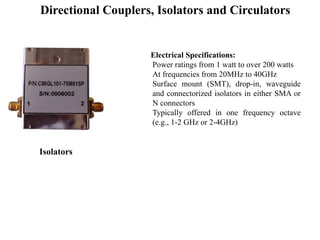
Isolators
Electrical Specifications:
Power ratingsfrom 1 watt to over 200 watts
At frequencies from 20MHz to 40GHz
Surface mount (SMT), drop-in, waveguide
and connectorized isolators in either SMA or
N connectors
Typically offered in one frequency octave
(e.g., 1-2 GHz or 2-4GHz)
Directional Couplers, Isolators and Circulators