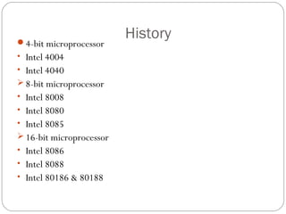
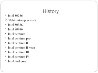
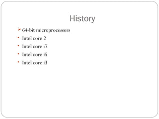
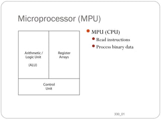
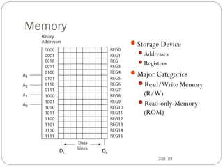
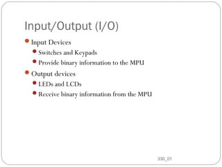
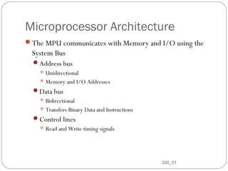
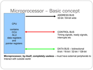
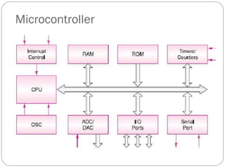
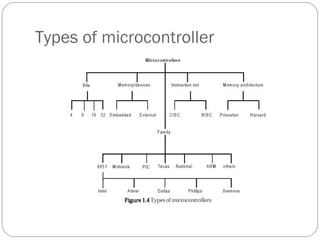
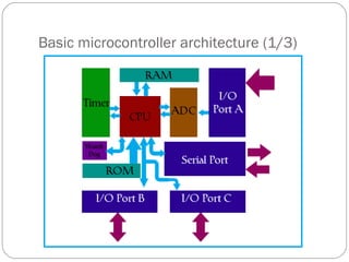
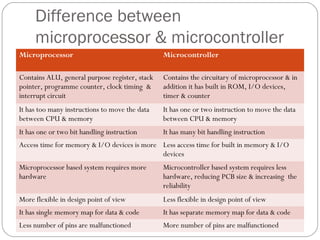
Presented by
Nitesh Kumar Singh
BME 7th
sem
Microprocessor and Microcontroller
Microprocessor
Introduction
The microprocessor also known as the central processing
unit, is the brain of all computers and many household and
electronic devices. Multiple microprocessors, working
together, are the "hearts" of datacenters, super-computers,
communications products, and other digital devices.
History
Fairchild Semiconductors (founded in 1957) invented the first IC
in 1959.
In 1968, Robert Noyce, Gordan Moore, Andrew Grove
resigned from Fairchild Semiconductors.
They founded their own company Intel (Integrated Electronics).
The first microprocessor invented was of 4-bit, after that 8-
bit,16-bit,.32-bit & 64-bit are founded
History
4-bit microprocessor
• Intel 4004
• Intel 4040
 8-bit microprocessor
• Intel 8008
• Intel 8080
• Intel 8085
 16-bit microprocessor
• Intel 8086
• Intel 8088
• Intel 80186 & 80188
History
• Intel 80286
 32-bit microprocessor
• Intel 80386
• Intel 80486
• Intel pentium
• Intel pentium pro
• Intel pentium II
• Intel pentium II xeon
• Intel pentium III
• Intel pentium IV
• Intel dual core
History
 64-bit microprocessors
• Intel core 2
• Intel core i7
• Intel core i5
• Intel core i3
Microprocessor (MPU)
MPU (CPU)
Read instructions
Process binary data
330_01
8
Memory
Storage Device
Addresses
Registers
Major Categories
Read/Write Memory
(R/W)
Read-only-Memory
(ROM)
330_01
9
D7 D0
Input/Output (I/O)
Input Devices
Switches and Keypads
Provide binary information to the MPU
Output devices
LEDs and LCDs
Receive binary information from the MPU
330_01
10
Microprocessor Architecture
The MPU communicates with Memory and I/O using the
System Bus
Address bus
Unidirectional
Memory and I/O Addresses
Data bus
Bidirectional
Transfers Binary Data and Instructions
Control lines
Read and Write timing signals
330_01
11
Microprocessor – Basic concept
CPU
contains
CCU
ALU
data registers
and
pointer registers
ADDRESS BUS
32-bit / 64-bit wide
CONTROL BUS
Timing signals, ready signals,
interrupts etc
DATA BUS – bidirectional
8-bit / 16-bit / 32-bit / 128-bit
Microprocessor, by-itself, completely useless – must have external peripherals to
Interact with outside world
Microcontroller
Micro controller
A self-contained system in which a processor, support, memory,
and input/output (I/O) are all contained in a single package.
A small computer system on a single IC
14
History of Microcontroller
First used in 1975(Intel 8048)
The introduction of EEPROM in 1993, allowed
microcontrollers to be electrically erased
The same year, Atmel introduced the first microcontroller using
Flash memory.
Microcontroller
Types of microcontroller
Basic Features of Microcontroller
Processor reset
Device clocking
Central processor
Program and Variable Memory (RAM)
I/O pins
Instruction cycle timers
More Sophisticated Features
Built-in monitor/debugger program
Interrupt capability
Analog I/O (PWM and variable dc I/O
Serial I/O (synchronous, a synchronous)
Parallel I/O (including direct interface to a master processor
External memory interface
Basic microcontroller architecture (1/3)
Basic microcontroller architecture (2/3)
Memory
RAM
ROM
Store data and code
CPU
Mathematical and logical operation
Memory units are called Register
Basic microcontroller architecture (3/3)
• BUS
– Group of 8,16 or more wires
– Three type, address bus, data bus and control bus
• Input-output unit
– port A, port B, port C … …
– Input, output and bidirectional ports
• Serial communication
• Timer unit
• Watchdog
– Automatic reset to prevent stall
• Analog to Digital Converter (ADC)
Processor Architecture
CISC
Large amount of instructions each carrying out a different
permutation of the same operation
Functionality of the instructions is more dependent upon
the processor’s designer.
RISC
Fundamental set of instructions
More control for users to design their own operations
Von Neumann Architecture
Processor Architecture
Princeton (Van Neumann) architecture
Common memory for program and data
Simple chip design
Execution of an instruction can take multiple
cycles
Processor Architecture
Princeton architecture example
Mov acc, reg
Cycle 1 Read instruction
Cycle 2 Read data out of
Ram and put into
Acc
Processor Architecture
Harvard architecture
Separate memory space program and data
Instructions are executed in one cycle
Easier timing of loops and delays
Harvard Architecture
Processor Architecture
Harvard architecture example
Mov acc, reg
Cycle 1 Execute previous
instruction
Read “move acc, reg”
Cycle 2 Execute “move acc,
reg” instruction
Block diagram of Microcontroller
Memory
The memory in a computer system stores the data and
instructions of the programs.
Adress
decoder Storage
Area
Adress
bus
Data
bus
Other signals
(Vcc,Gnd, CS,
etc.)
Microcontrollers Memory Types
Variable Area (RAM)
Control Store (ROM)
Program Counter Stack
I/O Space (Hardware interface Registers)
I/O Space
- Memory Mapped I/O Versus Programmed I/O
Programmed I/O
Special instructions such as IN and OUT are used to transfer
data between a CPU register and an external device.
Memory Mapped I/O
Standard instructions are used to transfer data between a CPU
register and an external device.
I/O ports appear as memory addresses.
Interrupts
 Instruction support for interrupts
 Internal CPU handling of interrupts
 Interruptible instructions
36
Instruction support for interrupts
Processors provide two instructions, enable priority
interrupt (EPI) and for disable priority interrupt (DPI).
These are atomic instructions that are used for many
purposes, such as buffering, within interrupt handlers, and
for parameter passing.
Internal CPU handling of interrupts
38
Step 1: finish the currently executing macroinstruction. Step 2: save the contents of the
program counter to the interrupt return location. Step 3: load the address held in the
interrupt handler location into the program counter. Resume the fetch and execute
sequence.
Single interrupt support
Internal CPU handling of interrupts
Step 1: complete the currently executing instruction. Step 2: save the contents of PC to
interrupt return location i. Step 3: load the address held in interrupt handler location i into the
PC. Resume the fetch-execute cycle.
Multiple interrupt support
Interruptible instructions
In rare instances individuation macroinstruction may need to be
interruptible.
This might be the case where the instruction takes a great deal of
time to complete. E.g. a memory to memory instruction that
moves large amounts of data.
In most cases, such an instruction should be interruptible between
blocks to reduce interrupt latency. However, interrupting this
particular instruction could cause data integrity problems.
Advantages of Microcontroller over
Microprocessor
Pin count down
Design time down, Board layout size down
Upgrade path easier – matching between peripherals for speed
Cost down – bulk purchases
Reliability up
Common software / hardware design environment available
from manufacturer
Issues when using microcontroller
 Two types of memory – speed issues when using
On-chip – fast, easy to access, “almost like a register”, limited amount of on-chip
memory available
Off-chip – slower
Use on-chip memory in a “cache” mode (copy off-chip data to on-chip when
processing data, then copy back)
 External components still there
E.g. Video CODECs – need to use DMA – Direct Memory Access – so that the
controller can get on with the “processing” and let something else worry about
moving data in and out of the chip
 Real time environment
Event driven – can’t WAIT for a device to become ready, can’t POLL to see if
device is ready, interrupt handling is key
 All these resources are “power hungry” and compete for resources (data busses
etc) – special features
Difference between
microprocessor & microcontroller
Microprocessor Microcontroller
Contains ALU, general purpose register, stack
pointer, programme counter, clock timing &
interrupt circuit
Contains the circuitary of microprocessor & in
addition it has built in ROM, I/O devices,
timer & counter
It has too many instructions to move the data
between CPU & memory
It has one or two instruction to move the data
between CPU & memory
It has one or two bit handling instruction It has many bit handling instruction
Access time for memory & I/O devices is more Less access time for built in memory & I/O
devices
Microprocessor based system requires more
hardware
Microcontroller based system requires less
hardware, reducing PCB size & increasing the
reliability
More flexible in design point of view Less flexible in design point of view
It has single memory map for data & code It has separate memory map for data & code
Less number of pins are malfunctioned More number of pins are malfunctioned
Thank you

microprocessormicrocontrollerbysanat-140107013112-phpapp02.pdf

  • 1.
    Presented by Nitesh KumarSingh BME 7th sem Microprocessor and Microcontroller
  • 2.
  • 3.
    Introduction The microprocessor alsoknown as the central processing unit, is the brain of all computers and many household and electronic devices. Multiple microprocessors, working together, are the "hearts" of datacenters, super-computers, communications products, and other digital devices.
  • 4.
    History Fairchild Semiconductors (foundedin 1957) invented the first IC in 1959. In 1968, Robert Noyce, Gordan Moore, Andrew Grove resigned from Fairchild Semiconductors. They founded their own company Intel (Integrated Electronics). The first microprocessor invented was of 4-bit, after that 8- bit,16-bit,.32-bit & 64-bit are founded
  • 5.
    History 4-bit microprocessor • Intel4004 • Intel 4040  8-bit microprocessor • Intel 8008 • Intel 8080 • Intel 8085  16-bit microprocessor • Intel 8086 • Intel 8088 • Intel 80186 & 80188
  • 6.
    History • Intel 80286 32-bit microprocessor • Intel 80386 • Intel 80486 • Intel pentium • Intel pentium pro • Intel pentium II • Intel pentium II xeon • Intel pentium III • Intel pentium IV • Intel dual core
  • 7.
    History  64-bit microprocessors •Intel core 2 • Intel core i7 • Intel core i5 • Intel core i3
  • 8.
    Microprocessor (MPU) MPU (CPU) Readinstructions Process binary data 330_01 8
  • 9.
  • 10.
    Input/Output (I/O) Input Devices Switchesand Keypads Provide binary information to the MPU Output devices LEDs and LCDs Receive binary information from the MPU 330_01 10
  • 11.
    Microprocessor Architecture The MPUcommunicates with Memory and I/O using the System Bus Address bus Unidirectional Memory and I/O Addresses Data bus Bidirectional Transfers Binary Data and Instructions Control lines Read and Write timing signals 330_01 11
  • 12.
    Microprocessor – Basicconcept CPU contains CCU ALU data registers and pointer registers ADDRESS BUS 32-bit / 64-bit wide CONTROL BUS Timing signals, ready signals, interrupts etc DATA BUS – bidirectional 8-bit / 16-bit / 32-bit / 128-bit Microprocessor, by-itself, completely useless – must have external peripherals to Interact with outside world
  • 13.
  • 14.
    Micro controller A self-containedsystem in which a processor, support, memory, and input/output (I/O) are all contained in a single package. A small computer system on a single IC 14
  • 15.
    History of Microcontroller Firstused in 1975(Intel 8048) The introduction of EEPROM in 1993, allowed microcontrollers to be electrically erased The same year, Atmel introduced the first microcontroller using Flash memory.
  • 16.
  • 17.
  • 18.
    Basic Features ofMicrocontroller Processor reset Device clocking Central processor Program and Variable Memory (RAM) I/O pins Instruction cycle timers
  • 19.
    More Sophisticated Features Built-inmonitor/debugger program Interrupt capability Analog I/O (PWM and variable dc I/O Serial I/O (synchronous, a synchronous) Parallel I/O (including direct interface to a master processor External memory interface
  • 20.
  • 21.
    Basic microcontroller architecture(2/3) Memory RAM ROM Store data and code CPU Mathematical and logical operation Memory units are called Register
  • 22.
    Basic microcontroller architecture(3/3) • BUS – Group of 8,16 or more wires – Three type, address bus, data bus and control bus • Input-output unit – port A, port B, port C … … – Input, output and bidirectional ports • Serial communication • Timer unit • Watchdog – Automatic reset to prevent stall • Analog to Digital Converter (ADC)
  • 23.
    Processor Architecture CISC Large amountof instructions each carrying out a different permutation of the same operation Functionality of the instructions is more dependent upon the processor’s designer. RISC Fundamental set of instructions More control for users to design their own operations
  • 24.
  • 25.
    Processor Architecture Princeton (VanNeumann) architecture Common memory for program and data Simple chip design Execution of an instruction can take multiple cycles
  • 26.
    Processor Architecture Princeton architectureexample Mov acc, reg Cycle 1 Read instruction Cycle 2 Read data out of Ram and put into Acc
  • 27.
    Processor Architecture Harvard architecture Separatememory space program and data Instructions are executed in one cycle Easier timing of loops and delays
  • 28.
  • 29.
    Processor Architecture Harvard architectureexample Mov acc, reg Cycle 1 Execute previous instruction Read “move acc, reg” Cycle 2 Execute “move acc, reg” instruction
  • 30.
    Block diagram ofMicrocontroller
  • 31.
    Memory The memory ina computer system stores the data and instructions of the programs. Adress decoder Storage Area Adress bus Data bus Other signals (Vcc,Gnd, CS, etc.)
  • 32.
    Microcontrollers Memory Types VariableArea (RAM) Control Store (ROM) Program Counter Stack I/O Space (Hardware interface Registers)
  • 33.
    I/O Space - MemoryMapped I/O Versus Programmed I/O Programmed I/O Special instructions such as IN and OUT are used to transfer data between a CPU register and an external device. Memory Mapped I/O Standard instructions are used to transfer data between a CPU register and an external device. I/O ports appear as memory addresses.
  • 34.
    Interrupts  Instruction supportfor interrupts  Internal CPU handling of interrupts  Interruptible instructions 36
  • 35.
    Instruction support forinterrupts Processors provide two instructions, enable priority interrupt (EPI) and for disable priority interrupt (DPI). These are atomic instructions that are used for many purposes, such as buffering, within interrupt handlers, and for parameter passing.
  • 36.
    Internal CPU handlingof interrupts 38 Step 1: finish the currently executing macroinstruction. Step 2: save the contents of the program counter to the interrupt return location. Step 3: load the address held in the interrupt handler location into the program counter. Resume the fetch and execute sequence. Single interrupt support
  • 37.
    Internal CPU handlingof interrupts Step 1: complete the currently executing instruction. Step 2: save the contents of PC to interrupt return location i. Step 3: load the address held in interrupt handler location i into the PC. Resume the fetch-execute cycle. Multiple interrupt support
  • 38.
    Interruptible instructions In rareinstances individuation macroinstruction may need to be interruptible. This might be the case where the instruction takes a great deal of time to complete. E.g. a memory to memory instruction that moves large amounts of data. In most cases, such an instruction should be interruptible between blocks to reduce interrupt latency. However, interrupting this particular instruction could cause data integrity problems.
  • 39.
    Advantages of Microcontrollerover Microprocessor Pin count down Design time down, Board layout size down Upgrade path easier – matching between peripherals for speed Cost down – bulk purchases Reliability up Common software / hardware design environment available from manufacturer
  • 40.
    Issues when usingmicrocontroller  Two types of memory – speed issues when using On-chip – fast, easy to access, “almost like a register”, limited amount of on-chip memory available Off-chip – slower Use on-chip memory in a “cache” mode (copy off-chip data to on-chip when processing data, then copy back)  External components still there E.g. Video CODECs – need to use DMA – Direct Memory Access – so that the controller can get on with the “processing” and let something else worry about moving data in and out of the chip  Real time environment Event driven – can’t WAIT for a device to become ready, can’t POLL to see if device is ready, interrupt handling is key  All these resources are “power hungry” and compete for resources (data busses etc) – special features
  • 41.
    Difference between microprocessor &microcontroller Microprocessor Microcontroller Contains ALU, general purpose register, stack pointer, programme counter, clock timing & interrupt circuit Contains the circuitary of microprocessor & in addition it has built in ROM, I/O devices, timer & counter It has too many instructions to move the data between CPU & memory It has one or two instruction to move the data between CPU & memory It has one or two bit handling instruction It has many bit handling instruction Access time for memory & I/O devices is more Less access time for built in memory & I/O devices Microprocessor based system requires more hardware Microcontroller based system requires less hardware, reducing PCB size & increasing the reliability More flexible in design point of view Less flexible in design point of view It has single memory map for data & code It has separate memory map for data & code Less number of pins are malfunctioned More number of pins are malfunctioned
  • 42.