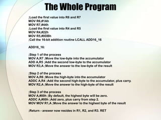
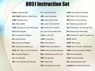
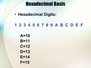
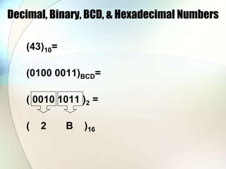
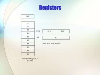
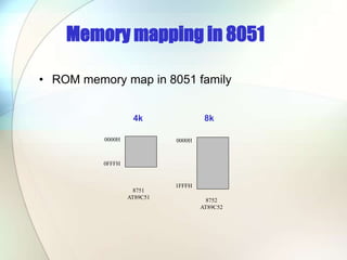
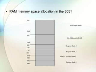
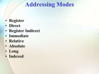
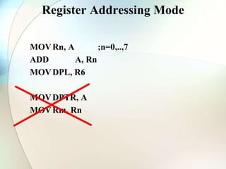
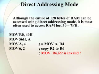
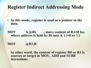
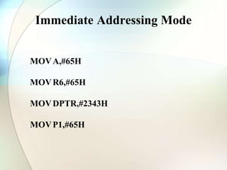
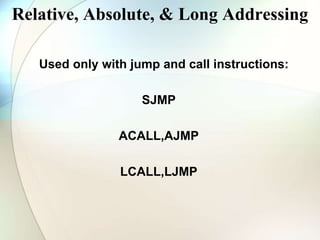
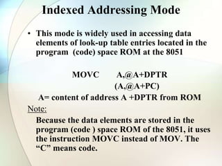
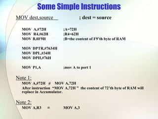
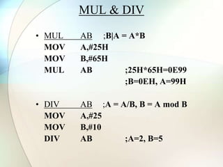
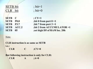
The document discusses numerical bases used in programming such as hexadecimal, binary, and BCD. It provides examples of converting between decimal, binary, hexadecimal and BCD representations of numbers. It also summarizes common registers, memory mapping, addressing modes, and basic instructions of the 8051 microcontroller.

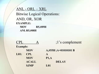
![ADDA, Source ;A=A+SOURCE
ADDA,#6 ;A=A+6
ADDA,R6 ;A=A+R6
ADD A,6 ;A=A+[6] or A=A+R6
ADD A,0F3H ;A=A+[0F3H]
SUBB A, Source ;A=A-SOURCE-C
SUBB A,#6 ;A=A-6
SUBB A,R6 ;A=A+R6](https://image.slidesharecdn.com/microcontroller8051-soft-220827022755-2ae6ea38/85/Microcontroller-8051-soft-ppt-16-320.jpg)
![DEC byte ;byte=byte-1
INC byte ;byte=byte+1
INC R7
DEC A
DEC 40H ; [40]=[40]-1](https://image.slidesharecdn.com/microcontroller8051-soft-220827022755-2ae6ea38/85/Microcontroller-8051-soft-ppt-19-320.jpg)