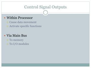
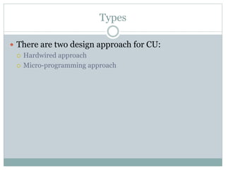
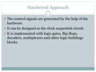
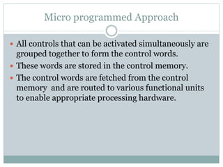
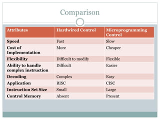
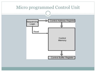
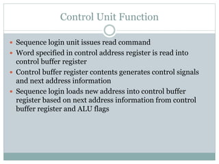
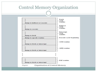
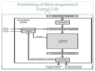
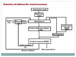
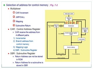
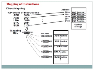
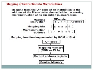
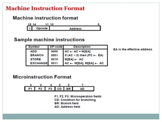
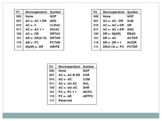
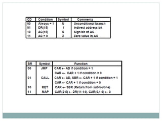
Introduction
Types
Comparison
Control Memory
Address Sequencing
Micro instruction format and Description
Control Unit
Introduction
 CU is the engine that runs the entire computer with
the help of the control signals.
 It perform the correct sequencing of the correct
signals.
 It controls everything with a few control signals that
points within processor and a few control signals to
the system bus.
Introduction
 All the micro-operation are controlled by CU by
performing two basic tasks:
 Sequencing: It causes the processor to step through the series
of micro-operation in proper sequence, based on program
being executed.
 Execution: It causes each micro-operation to be performed.
Control Signal Sources
 Clock
 It helps to synchronize the operation. It causes one micro-
operation to be performed for each clock pulse
 Instruction Register
 Op-code for current instruction
 Determines which micro-instructions are performed
 Flags
 State of CPU
 Results of previous operations
Control Signal Sources
 From Control Bus
 Interrupts / Bus Requests
 Acknowledgements
Control Signal Outputs
 Within Processor
 Cause data movement
 Activate specific functions
 Via Main Bus
 To memory
 To I/O modules
Types
 There are two design approach for CU:
 Hardwired approach
 Micro-programming approach
Hardwired Approach
 The control signals are generated by the help of the
hardware.
 It can be designed as the clock sequential circuit.
 It is implemented with logic gates, flip-flops,
decoders, multiplexers and other logic buildings
blocks.
Micro programmed Approach
 All controls that can be activated simultaneously are
grouped together to form the control words.
 These words are stored in the control memory.
 The control words are fetched from the control
memory and are routed to various functional units
to enable appropriate processing hardware.
Comparison
Attributes Hardwired Control Microprogramming
Control
Speed Fast Slow
Cost of
Implementation
More Cheaper
Flexibility Difficult to modify Flexible
Ability to handle
complex instruction
Difficult Easier
Decoding Complex Easy
Application RISC CISC
Instruction Set Size Small Large
Control Memory Absent Present
Micro programmed Control Unit
Control Unit Function
 Sequence login unit issues read command
 Word specified in control address register is read into
control buffer register
 Control buffer register contents generates control signals
and next address information
 Sequence login loads new address into control buffer
register based on next address information from control
buffer register and ALU flags
Next Address Decision
 Depending on ALU flags and control buffer register
 Get next instruction
 Add 1 to control address register
 Jump to new routine based on jump microinstruction
 Load address field of control buffer register into control address
register
 Jump to machine instruction routine
 Load control address register based on opcode in IR
Control Memory Organization
Functioning of Micro programmed
Control Unit
Selection of address for control memory
Conditional Branching
Mapping of Instructions
Mapping of Instructions to Microroutines
Machine Instruction Format
Micro Programmed Control Unit

Micro Programmed Control Unit

  • 1.
  • 2.
    Introduction  CU isthe engine that runs the entire computer with the help of the control signals.  It perform the correct sequencing of the correct signals.  It controls everything with a few control signals that points within processor and a few control signals to the system bus.
  • 3.
    Introduction  All themicro-operation are controlled by CU by performing two basic tasks:  Sequencing: It causes the processor to step through the series of micro-operation in proper sequence, based on program being executed.  Execution: It causes each micro-operation to be performed.
  • 5.
    Control Signal Sources Clock  It helps to synchronize the operation. It causes one micro- operation to be performed for each clock pulse  Instruction Register  Op-code for current instruction  Determines which micro-instructions are performed  Flags  State of CPU  Results of previous operations
  • 6.
    Control Signal Sources From Control Bus  Interrupts / Bus Requests  Acknowledgements
  • 7.
    Control Signal Outputs Within Processor  Cause data movement  Activate specific functions  Via Main Bus  To memory  To I/O modules
  • 8.
    Types  There aretwo design approach for CU:  Hardwired approach  Micro-programming approach
  • 9.
    Hardwired Approach  Thecontrol signals are generated by the help of the hardware.  It can be designed as the clock sequential circuit.  It is implemented with logic gates, flip-flops, decoders, multiplexers and other logic buildings blocks.
  • 10.
    Micro programmed Approach All controls that can be activated simultaneously are grouped together to form the control words.  These words are stored in the control memory.  The control words are fetched from the control memory and are routed to various functional units to enable appropriate processing hardware.
  • 11.
    Comparison Attributes Hardwired ControlMicroprogramming Control Speed Fast Slow Cost of Implementation More Cheaper Flexibility Difficult to modify Flexible Ability to handle complex instruction Difficult Easier Decoding Complex Easy Application RISC CISC Instruction Set Size Small Large Control Memory Absent Present
  • 12.
  • 13.
    Control Unit Function Sequence login unit issues read command  Word specified in control address register is read into control buffer register  Control buffer register contents generates control signals and next address information  Sequence login loads new address into control buffer register based on next address information from control buffer register and ALU flags
  • 14.
    Next Address Decision Depending on ALU flags and control buffer register  Get next instruction  Add 1 to control address register  Jump to new routine based on jump microinstruction  Load address field of control buffer register into control address register  Jump to machine instruction routine  Load control address register based on opcode in IR
  • 15.
  • 16.
    Functioning of Microprogrammed Control Unit
  • 17.
    Selection of addressfor control memory
  • 19.
  • 20.
  • 21.
    Mapping of Instructionsto Microroutines
  • 22.