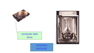
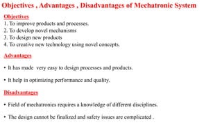
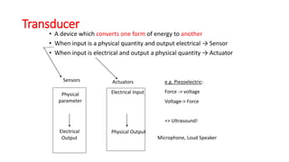
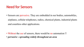
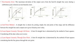
MECHATRONICS
(MEng4204)
for 4th Year
B.Sc. Mechanical Engineering
Part-2
By
Dr. B.K. Singh
Professor
Department of Mechanical Design & Manufacturing Engineering
School of Mechanical, Chemical & Materials Engineering
Adama Science & Technology University
Ethiopia
INTRODUCTION TO MECHATRONICS
• Mechatronics is a japanese word which denotes the combination of “mecha” from
mechanism and
“ tronics” from electronics.
Mechatronics = mechanics+ electronics + computing
DEFINITION
Mechatronics is defined as a multi-disciplinary field of study that implies the
synergistic integration of electronic engineering, electrical engineering , control
engineering and intelligent computer control with mechanical engineering for the
design and manufacture of products and processes
• Synergistic – means various parts
Bird’s Eye View of Mechatronics
Mechatronic system
• The interfacing components present in a mechatronics field
connected to form a system known as mechatronic system.
• The interfacing components are mechanical system, electrical system,
electronic system etc.
System
• A system may be defined as a black box which has an input and an
output. System is concerned only with the relationship between the
input and output and not on the process going on inside the box.
input motor output
Electric power Rotation
Elements of a Mechatronic system
Block diagram of a mechatronic system
Function of Elements in Mechatronic system
 The actuators produce motion or cause some action;
 The sensors detect the state of the system parameters, inputs and outputs;
 Digital devices control the system;
 Conditioning and interfacing circuits provide connection between the control
circuit and the input/output devices;
 Graphical displays provide visual feedback to users.
Development of mechatronics has gone
through three stages
• First level – Introducing time : technologies used in mechatronics system
developed rather independently and individually.
• Second level – Synergistic integration of different technologies started taking
place
Ex: Op to electronics (Integration of optics and electronics)
• Third level- Increased use of computational intelligence in mechatronics product
and system. // Machine Intelligence Quotient (MIQ)
• Possibility of miniaturization of components (in the form of micro actuators and
micro sensors) // micro mechatronics
Levels of Mechatronic Systems’ Integration
First Level
 —
conveyors,
 —
rotary tables,
 —
auxiliary manipulators
Second Level
 Operated power machines (turbines and generators)
 Machine tools and industrial robots with numerical program management
Third Level
Synthesis of new precise, information and measuring high technologies
gives a basis for designing and producing intellectual mechatronic modules
and systems.
Examples of mechatronic systems
• Computers, Disk drives, Photocopiers, Scanners, fax machines, washing
machines, CNC machines, Vacuum cleaners, Televisions, Digital cameras,
CD players, Air conditioning units, Security systems, Automatic gate
control system, Robots, Automated Guided Vehicles (AGV), Automatic
teller machines, Flight control actuators, Landing gear systems etc.
computer disk
drive
WASHING
MACHINE
USA Strategy for Mechatronics
 Understand the existing process
 Simplify the process
 Automate the process
Mechatronics leads to
 Increase labour productivity and reduce labour cost
 Mitigate the effects of labour shortage
 Reduce or eliminate routine manual or clerical tasks
 Improve safety – Worker and system.
 Improve product quality
 Reduce manufacturing lead time
 Accomplish processes that cannot be done manually
Objectives
1. To improve products and processes.
2. To develop novel mechanisms
3. To design new products
4. To creative new technology using novel concepts.
Advantages
• It has made very easy to design processes and products.
• It help in optimizing performance and quality.
Disadvantages
• Field of mechatronics requires a knowledge of different disciplines.
• The design cannot be finalized and safety issues are complicated .
Objectives , Advantages , Disadvantages of Mechatronic System
Mechatronics Applications
• Medical --- Implant devices, assisted surgery.
• Defence --- Under water vehicles, jet engines.
• Automotive ---Climate control, antilock brake, cruise control, air bags,
speedometer display.
• Manufacturing --- Robotics , Machines
• Smart consumer products --- Toys
• Electronic home appliances --- Home security, microwave oven,
washing machine, cameras, sewing machines etc.
MEASUREMENT SYSTEM:
It can be defined as a black box which is used for making measurements. It has the input as the quantity being
measured and the output as a measured value of that quantity.
Example:
Elements of Measurement Systems:
Measurement system consists of the following three elements.
a) Sensor b) Signal conditioner c) Display System
Sensors
Sensor
Input Signal Output Signal
Sensors are electronic devices that measure the physical quantity or produces a signal
relating to the quantity being measured.
 A sensor acquires a physical quantity and converts it into a signal suitable for processing (e.g.
optical, electrical, mechanical)
Physical quantities can be temperature, pressure, light….
Nowadays common sensors convert measurement of physical phenomena into an electrical
signal
Active element of a sensor is called a transducer
Transducer
• A device which converts one form of energy to another
• When input is a physical quantity and output electrical → Sensor
• When input is electrical and output a physical quantity → Actuator
Sensors
Physical
parameter
Electrical
Output
Electrical Input
Physical Output
e.g. Piezoelectric:
Force -> voltage
Voltage-> Force
=> Ultrasound!
Microphone, Loud Speaker
Actuators
Transducers, Sensors and Actuator
• Transducers are electric or electronic devices that transform energy from one form to
another. Transducers are elements that when subject to some physical change
experience a related change.
• Sensor is an element which produces a signal relating to the quantity being measured.
• An actuator accepts energy and produces movement (action).
Commonly Measured Quantities
Stimulus Quantity
Acoustic Wave (amplitude, phase, polarization), Spectrum, Wave
Velocity
Biological & Chemical Fluid Concentrations (Gas or Liquid)
Electric Charge, Voltage, Current, Electric Field (amplitude, phase,
polarization), Conductivity, Permittivity
Magnetic Magnetic Field (amplitude, phase, polarization), Flux,
Permeability
Optical Refractive Index, Reflectivity, Absorption
Thermal Temperature, Flux, Specific Heat, Thermal Conductivity
Mechanical Position, Velocity, Acceleration, Force, Strain, Stress,
Pressure, Torque
Choosing a Sensor
Need for Sensors
• Sensors are pervasive. They are embedded in our bodies, automobiles,
airplanes, cellular telephones, radios, chemical plants, industrial plants
and countless other applications.
• Without the use of sensors, there would be no automation !!
• pervasive --spreading widely throughout an area
b) Signal Conditioner
It receives signal from the sensor and manipulates it into a suitable condition for display. It performs filtering,
amplification or other signal conditioning on the sensor output.
Example
Temperature measurement – Single Conditioner function (Amplifier)
Input – Small E.M.F value (From sensor)
Output – Big E.M.F Value (Amplified).
c) Display System:
A display system displays the data (output) from the signal conditioner by analog or digital.
A digital system is a temporary store such as recorder.
Example:
Display – L.E.D (or) Number on scale by pointer movement
Input – Conditioned Signal (from signal conditioner)
Output – Value of the quantity (Temperature)
Temperature Measurement System
Control System:
It is a black box which is used to control its output in a pre-set value.
OPEN LOOP CONTROL SYSTEM:
 If there is no feedback device to compare the actual value with desired one.
 No control over its input.
CLOSED LOOP CONTROL SYSTEM:
 If there is feedback device to compare the actual value with desired one.
Elements of Closed Loop System:
The elements of closed loop control system are
 Comparison Unit
 Control Unit
 Correction Unit
 Process Unit
 Measurement Device
Example
System of Controlling Room Temperature
Controlled Variable : Room temperature
Reference Variable : Required Room temperature (pre-set value)
Comparison Element : Person compares the measured value with required value
Error Signal : Different between the measured and required temperatures.
Control Unit : Person
Correction Unit : The switch on the fire Process :
Heating by the fire Measuring Device : Thermometer.
System of Controlling Water Level
Controlled variable : Water level in the tank
Reference variable : Initial setting of the float and lever position
Comparison Element : The lever
Error signal : Difference between the actual & initial setting of the lever positions
Control Unit : The pivoted lever
Correction Unit : The flap opening or closing the water supply
Process : The water level in the tank
Measuring device : The floating ball and lever
Automatic Speed Control of Rotating Shaft
Potentiometer - To set the reference value (Voltage to be supplied to differential amplifier)
Differential amplifier - To compare amplify the difference between the reference and feedback values
Tachogenerator - To measure the speed of the rotating shaft and is connected to the rotating shaft
by means of a pair of level gears
SEQUENTIAL CONTROLLERS:
It is used to control the process that are strictly ordered in a time or sequence.
Domestic Washing Machine
Pre Wash Cycle:
Pre-wash cycle may involve the following sequence of operations.
 Opening of valve to fill the drum when a current is supplied.
 Microprocessor is used to operate the switch for opening-closing the valve.
 Closing the valve after receiving the signal from a sensor when the required level of water is filled in the
washing drum.
 Stopping the flow of water after the current is switched off by the microprocessor.
 Switch on the motor to rotate for stipulated time.
 Initiates the operation of pump to empty the water from the drum.
 Pre-wash cycle involves washing the clothes in the d m by cold water.
Main Wash Cycle:
Main wash cycle involves washing the clothes in the drum by hot water and the sequence of operations in main wash
is as follows:
 Cold water is supplied after the Pre-wash cycle is completed.
 Current is supplied in large amount to switch on the heater for heating the cold water.
 Temperature sensor switches off the current after the water is heated to required temperature.
 Microprocessor or cam switch ON the motor to rotate the drum.
 Microprocessor or cam switches on the current to a discharge pump to empty the drum.
Rinse Cycle:
Rinse cycle involves washing out the clothes with cold water a number of times and the sequence of operations in a
Rinse cycle are as follows:
 Opening of valve to allow cold water into the drum when the microprocessor are given signals to supply current
after the main wash cycle is completed.
 Switches off the supply current by the signals from microprocessor
 Operation of motor to rotate the drum
 Operation of pump to empty the drum and respect this sequence a number of times.
Spinning Cycle: Spinning cycle involves removing of water from the clothes and the sequence of operations is
 Switching on the drum motor to rotate it at a higher speed than a rinsing cycle.
Automatic Camera
Engine Management System
PERFORMANCE CHARACTERISTICS
• Static and Dynamic Characteristics
• The Static characteristics are the values given after the steady-
state conditions occur, i.e. the values given when the transducer
has settled down after receiving some input.
Static
Dynamic
PERFORMANCE TERMINOLOGY:
Static Characteristics:
Range and Span:
 The region between the limits within which an input can vary is called the range of a sensor. .
 The difference between the limits (maximum value - minimum value) is known as span of sensor.
 Example a load cell is used to measure force. An input force can vary from 20 to 100N.
 Then the range of load cell is 20 to 100 N. And the span of load cell is 80 N (i.e., 100- 20)
Error:
 The algebraic difference between the indicated value and the true value of the measured parameter is termed as the error of
the device.
 Error = Indicated value — true value
 Example, if the transducer gives a temperature reading of 30°C when the actual temperature is 29° C, then the error is +
1°C. If the actual temperature is 3 1° C, then the error is — 1°C.
Accuracy:
 It is defined as the ability of the instrument to respond to the true value of the measure variable under the reference
conditions.
 For example, a thermocouple has an accuracy of ± 1° C.
 This means that reading given by the thermocouple can be expected to lie within + 1°C (or) — 1°C of the true value.
 Accuracy is also expressed as a percentage of the full range output (or) full scale deflection.
 Example, a thermocouple can be specified as having an accuracy of ±4 % of full range output. Hence if the range of the
thermocouple is 0 to 200°C, then the reading given can be expected to be within + 8°C (or) — 8°C of the true reading.
• Precision: It is defined as the degree of exactness for which the instrument is intended to
perform.
• Resolution: Resolution or Discrimination is the smallest change in the input value that is
required to cause an appreciable change in the output.
• Sensitivity : It is defined as the ratio of the change in output signal to change in the input
quantity. Sensitivity = Output/Input.
If the sensitivity is constant , then the sensor is said to be linear one. If the sensitivity is
variable, then the sensor is said to be non-linear one.
• Noise: A signal generated by internal circuitry or external interference that is superimposed or added to the output
signal.
• Drift: The term drift is an undesirable change or gradual departure in output over a period of time that is unrelated
to change in input, operating conditions or load. Zero drift is used when there is a change in output at zero input.
• Threshold is the minimum value of the input required to cause the pointer to move from zero position.
• Dead band or Dead zone is the largest range of input values for which there is no output. It is caused by factors
such as friction, backlash and hysteresis.
• Backlash may be defined as the maximum distance or angle through which part of a mechanical system can be
moved without causing any motion of next part of the system.
• Stability: The stability of a transducer is its ability to give the same output when used to measure a constant input
over a period of time.
• Dead time: It is the time required by a transducer to begin to respond to a change in input value.
•
a) End Point Method : A straight line is drawn by joining simply the end points of the range and the difference
between the straight line and a output curve gives linearity error value.
b) Least Square Linearity Through All Points : A best fit straight line is determined by the method of least squares.
Considering all the data values are in error.
c) Least Square Linearity Through Zero Point : A best fit straight line is determined by the method of least squares
considering that the line passes through the zero point.
• Non-linearity Error: The maximum deviation of the output curve from the best-fit straight line curve during a
calibration cycle is known as non-linearity error.
Hysteresis Error
• When input increases, output also increases and a calibration curve can be drawn. If input is
decreased from maximum value and if output does not follow the same curve, then there will be
a residual output when input is zero. This phenomenon is called hysteresis.
• The algebraic difference in output for increasing and decreasing values is known as Hysteresis
Error.
Dynamic Characteristics
• The Dynamic characteristics refer to the behaviour between the time that the input value
changes and the time that the value given by the transducer settles down to the steady-state.
• Speed of response: Indicates how fast the sensor (measurement system) reacts to changes in the
input variable. (Step input)
• Rise time: Rise time is the time required for the output to rise from 10% to 95% of the steady
state value.
• Time constant: The time constant is the measure of the inertia of the sensor and so how fast it
will react to changes in its input. The time for the output to change by 63.2% of its maximum
possible change.
• Settling time: Settling time is the time taken by a system to be within a close range of its steady-
state value.
• Frequency Response describe how the ratio of output and input changes with the input
frequency. (sinusoidal input)
• Dynamic error, δ(ω) = M(ω) - 1a measure of the inability of a system or sensor to adequately
reconstruct the amplitude of the input for a particular frequency
• Bandwidth of a system is the range of frequencies for which its dynamic sensitivity is
satisfactory.
• Settling time is the time taken by a system to be within a close range of its steady-state value.
SELECTION OF DISPLACEMENT, POSITION & PROXIMITY SENSOR:
 Size of the displacement (mm)
 Displacement type (Linear or angular)
 Resolution required
 Accuracy Required
 Material of the object
 Cost
DISPLACEMENT SENSORS
 Displacement sensors are contact type sensor
Types of Displacement sensors:
(i) Potentiometer
(ii) Strain gauge
(iii) Capacitive sensors
(iv) Linear variable differential transformer
(i) POTENTIOMETER
PRINCIPLE:
It works on variable resistance transduction principle
Linear or Rotary potentiometer is a variable resistance displacement transducer which uses the
variable resistance transduction principle in which the displacement or rotation is converted into
a potential difference due to the movement of sliding contact over a resistive element
CONSTRUCTION & WORKING:
A resistor with three terminals.
Two end terminal & one middle terminal (wiper)
Two end terminal are connected to external input voltage
One middle and one end terminal as output voltage
The slider determines the magnitude of the potential difference developed
Characteristics:
Resistance element = Precision Drawn wire with a diameter of about 25 to 50 microns, and wad over a cylindrical
or a flat mandrel of ceramic, glass or Anodized Aluminium. 2mm to 500 mm in case of linear pot.
= For high resolution, wire is made by using ceramic (cermet) or conductive plastic film due to low noise levels.
Wipers (Sliders) = Tempered phosphor bronze, beryllium copper or other precious alloys.
Wire Material = Strong, ductile and protected from surface corrosion by enameling or oxidation. Materials are alloys
of copper nickel, Nickel chromium, and silver palladium.
= Resistivity of wire ranges from 0.4 µΩm to 13 µΩm
Resistance range = 20Ω to 200KΩ and for plastic 500Ω to 80KΩ
Accuracy = Higher temperature coefficient of resistance than the wire and so temperature changes have a greater
effect Accuracy.
(ii) STRAIN GAUGE:
 Strain gauges are passive type resistance sensor whose electrical resistance change when it is stretched or
compressed (mechanically strained) under the application of force.
 The electrical resistance is changed due to the change in length (increases) and cross sectional area (decreases) of
the strain gauge.
 This change in resistance is then usually converted into voltage by connecting one, two or four similar gauges
as an arm of a Wheatstone bridge (known as Strain Gauge Bridge) and applying excitation to the bridge. The
bridge output voltage is then a measure of strain, sensed by each strain gauge.
Unbonded Type Strain Gauges:
 In unbonded type, fine wire filaments (resistance wires) are stretched around rigid and electrically
insulated pins on two frames.
 One frame is fixed and the other is movable.
 The frames are held close with a spring loaded mechanism.
 Due to the relative motion between two frames, the resistance wires are strained.
 This strain is then can be detected through measurement of the change in electrical resistance since they
are not cemented with the surfaces, they can be detached and reused.
Bonded Type Strain Gauges:
 Bonded type strain gauges consists of resistance elements arranged in the form of a grid of fine wire,
which is cemented to a thin paper sheet or very thin Bakelite sheet, and covered with a protective sheet
of paper or thin Bakelite.
 The paper sheet is then bonded to the surface to be strained. The gauges have a bonding material which
acts an adhesive material during bonding process of a surface with the gauge element.
Classification of Bonded Type Strain Gauges:
(a) Fine wire gauges
(b) Metal foil gauges
(c) Semiconductor filament type
(a) Fine Wire Gauges:
Wire of 3 to 25 microns diameter is arranged in the form of grid consisting of parallel loops
(b) Metal Foil Gauges:
 A thin foil of metal, deposited as a grid pattern onto a plastic backing material using polyimide.
 Foil pattern is terminated at both ends with large metallic pads
 Entire gauge size 5- 15mm
 Adhesive directly bonded to the gauge usually epoxy
(c) Semiconductor Filament Type:
 The gauges are produced in wafers from silicon or germanium crystals
 Special impurities such as boron is added
 It is mounted on an epoxy resin backing with copper on nickel leads
 Filament about 0.05mm thick 0.25mm wide and 1.25 to 12mm length
(iii) CAPACITIVE SENSORS:
It is used for measuring, displacement, velocity, force etc..
Principle:
It is passive type sensors in which equal and opposite charges are generated on the plates due to
voltage applied across the plate which is separated by dielectric material.
Formula
By Changing the Distance between Two Plates:
The displacement is measured due to the change in capacitance
By Varying the Area of Overlap:
 The displacement causes the area of overlap to vary
 The capacitance is directly proportional to the area of the plates and varies linearly with
changes in the displacement between the plates
By Varying the Dielectric Constant:
 The change in capacitance can be measured due to change in dielectric constant as a result of
displacement.
 When the dielectric material is moved due to the displacement, the material causes the dielectric
constant to vary in the region where the two electrodes are separated that results in a change in
capacitance.
Push Pull Sensor:
 Push pull displacement sensor is used to overcome the non-linearity error.
 The sensor consists of three plates with the upper pair forming one capacitor and the lower pair forming
another capacitor.
 The displacement moves central plate between the two other plates.
 If the central plate moves downwards.
 The plate separation of the upper capacitor increases and the separation of the lower one decreases.
(iv) LINEAR VARIABLE DIFFERENTIAL
TRANSFORMER:
 It consists of three symmetrically spaced coils.
 The centre coil is primary coil and other two
are secondary coil
 Secondary coils are connected in series
opposition and equally positioned with respect
to primary coil
 The output voltage is proportional to the
displacement of the core from null position
PROXIMITY SENSORS
Proximity sensors are non – contact type sensor.
Types of Proximity Sensor:
(i) Eddy current proximity sensor
(ii) Inductive proximity sensor
(iii) Pneumatic proximity sensor
(iv) Proximity switches
(i) EDDY CURRENT PROXIMITY SENSOR:
PRINCIPLE:
 When a coil is supplied with alternating current, an alternating magnetic field is produced
which induces an EMF on it.
 If there is a metal near to this alternating magnetic field, on EMF is induced in it.
 The EMF cause current to flow. This current flow is eddy current.
CONSTRUCTION & WORKING:
 It has two identical coils.
 One reference coil & another sensing coil which senses the magnetic current in the object.
 Eddy current start to flow due to AC(conducting object) close to sensor
 Eddy current produce a magnetic field to oppose the magnetic field generated by sensing coil.
 Due to this opposition reduction flux is created. To detect 0.001mm
(ii) INDUCTIVE PROXIMITY SENSORS:
 It consists of coil wound round a core.
 Metal is close to coil Inductance changes occurs.
 It is suitable for ferrous metals
(iii) PNEUMATIC PROXIMITY SWITCHES:
 It is suitable for sensing non conducting materials
 Air is allowed to escape from the front side of the sensor.
 When there is no object air escapes freely.
 When there is an object, the escaping air is blocked and return backed to system.
 It is used to measure the range 3mm to 12mm
(iv) PROXIMITY SWITCHES:
 It is used in robotics for sensing elements
 It is also used in NC machines, material handling systems and assembly lines.
(a) Micro switch
(b) Reed switch
(c) Photo sensitive switch
(d) Mechanical switch
(a) Micro switch
 It is limit switch operated by levers, rollers & cams
 It is switch which requires physical contact and small force to close the contacts.
 Example a belt conveyor.
(b) Reed Switch:
 It is a non – contact proximity switch that
consists of two magnetic switch contacts
enclosed in a glass tube fined with an inert
gas.
 When magnet is closed switch is operated.
 Used for high speed applications.
(c) Photo Sensitive Devices:
 It is used to sense opaque object.
 Photo detector receives a beam of light produced by the LED.
 Object is passed the beam gets broken or reflected when is detected.
Optical Encoders
It is used to position, velocity, acceleration and direction of movement of rotors.
(i) Incremental Encoders
PRINCIPLE:
 When a beam of light passes through slots in a disc, it is sensed by the light sensor opposite to
the light source.
 When the disk is rotated, a pulsed output is produced by sensor with number of pulses being
proportional to the position of the disc and number of pulses per second determines the velocity
of the disk.
Construction and working
 It consists three components light source,
coded disk and photo detector.
 The disk is made up of plastic or glass.
 The disk consists of opaque and transparent
segment alternatively.
 The wheel is between light and photo detector.
 The photo detector receives the light signal
alternatively which is converted into
electrical signal.
(ii) ABSOLUTE ENCODERS
PRINCIPLE:
The principle of operation is that they provide a unique output corresponds to each rotational position of the shaft.
The output is in the form of binary numbers representing the angular position.
CONSTRUCTION & WORKING:
 The disc has four concentric slots and four photo detectors to detect the light pulse.
 The slots are arranged in such way that they give a binary number.
 It consist opaque and transparent segments. This pattern is called as track.
 The encoders have 8 to 14 slots.
 The number of the track determines the resolution of the encoder.
HALL EFFECT SENSORS:
Principle:
 When a current carrying semiconductor plate is placed in a transverse magnetic field, it experiences a force (Lorentz force).
Due to this action a beam of charged particles are forced to get displaced from its straight path. This is known as Hall Effect.
 A current flowing in a semiconductor plate is like a beam of moving charged particles and thus can be deflected by a
magnetic field.
 The side towards which the moving electron deflected becomes negatively charged and the other side of the plate becomes
positively charged or the electrons moving away from it.
 This charge separation produces an electrical voltage which continues until the Lorentz force on the charged particles from
the electric field balances the forces produced by the magnetic field.
 The result is a traverse potential difference known as Hall voltage.
Construction & Working:
 Current is passed through leads 1 and 2 of the semiconductor plate and the output leads are connected to the element faces 3
and 4.
 These output faces are at same potential when there is no transverse magnetic field passing through the element and
voltage known as Hall voltage appears when a transverse magnetic field is passing through the element.
 This voltage is proportional to the current and the magnetic field.
 The direction of deflection depends on the direction of applied current and the direction of magnetic field.
Fluid Sensors
Fluid Pressure Sensors:
Diaphragm Type:
 In the diaphragm type sensor, when there is a difference in pressure between the two sides then the centre of the
diaphragm becomes displaced.
 Corrugations in the diaphragm result in a greater sensitivity.
 This movement can be monitored by some form of displacement sensor, e.g: a strain gauge.
 A specially designed strain gauge is often used, consisting of four strain gauges with two measuring the strain in a
circumferential direction while two measure strains in a radial direction
 The four strain gauges are then connected to form the arm of a Wheatstone bridge.
 While strain gauges can be stuck on a diaphragm, an alternative is to create a silicon diaphragm with the strain
gauges as specially doped areas of the diaphragm.
Capsule and Bellow Types:
 Capsules are two corrugated diaphragms combined to give greater
accuracy
 Capsules and bellows are made up of stainless steel, phosphor bronze,
and nickel with rubber and nylon
Pressure range 103
to 108
Pa
Tube Pressure Sensor:
 A different form of deformation is obtained using a tube with an elliptical cross section. Increase in pressure in tube causes it
tend to circular cross – section.
 C – Shaped tube is generally known as a Bourdon tube. C opens when pressure in the tube increases
 A helical form gives more sensitivity
 Tubes are made up of stainless steel, phosphor bronze, and nickel with rubber and nylon.
Pressure range 103
to 108
Pa
Piezoelectric Sensors:
 Piezoelectric materials when stretched or compressed generate electric charges with one face of the managerial becoming
positively charged and the opposite face negatively charged.
 As a result a voltage is produced. The net charge q on a surface is proportional to the amount x by which the charges have
been displaced, and since the displacement is proportional to the applied force F.
 q = kx= SF
Where k is a constant and S a constant termed the charge sensitivity
Tactile Sensor:
 It is used on fingertips of robot hands and for touch display screen
 It uses piezoelectric poly-vinylidene fluoride (PVDF) film
 Two layers are separated by sift film
 The lower PVDF film has an alternating voltage applied to it results
in mechanical oscillations
 Intermediate film transmits the vibration to upper film
LIQUID FLOW SENSORS:
Turbine Flow Meter:
 The turbine flow meter and it consists of a multi-bladed rotor which
is supported in the pipe along with the flow occurs.
 The rotor rotation depends upon the fluid flow and the angular
velocity is proportional to the flow rate.
 The rotor rotation is determines the magnetic pick-up, which is
connected to the coil.
 The revolution of the rotor is determined by counting the number of
pulses produced in the magnetic pick up. The accuracy of this
instrument is ± 3%.
Orifice Plate:
 It is a simple disc with a central hole and it is placed in the tube through which the fluid
flows.
 The pressure difference measured between a point equal to the diameter of the tube
upstream and half the diameter of downstream.
 The accuracy of this instrument is ±1.5%.
LIQUID LEVEL MEASUREMENT:
Differential Pressure Sensor:
 In this the differential pressure cell determines the pressure
difference between base of the liquid and atmospheric pressure.
 The differential pressure sensor can be used in either form of open
or closed vessel system.
Float System:
 In this method the level of liquid is measured by movement of a float.
 The movement of float rotates the arm and slider will move across a potentiometer.
 The output result is related to the height of the liquid.
TEMPERATURE SENSORS:
Bimetallic Strips:
 A Bimetallic thermostat consists of two different metal strips bounded
together and they cannot move relative to each other.
 These metals have different coefficients of expansion and when the
temperature changes the composite strips bends into a curved strip, with the
higher coefficient metal on the outside of the curve.
 The basic principle in this is all metals try to change their physical
dimensions at different rates when subjected to same change in temperature.
 This deformation may be used as a temperature- controlled switch, as in the
simple thermostat.
Resistance Temperature Detectors (RTDs):
 The materials used for RTDs are Nickel, Iron, Platinum, Copper, Lead,
Tungsten, Mercury, Silver, etc. The Resistance temperature detectors are simple and
resistive elements in the form of coils of wire.
 The equation which is used to find the linear relationship in RTD is
 The resistance of most metals increases over a limited temperature range and
the relationship between Resistance and Temperature is shown in the side.
Constructional Details of RTDs:
 The platinum, nickel and copper in the form wire are the most commonly used
materials in the RTDs.
 Thin film platinum elements are often made by depositing the metal on a
suitable substrate wire- wound elements involving a platinum wire held by a high
temperature glass adhesive inside a ceramic tube.
Thermistors:
 Thermistor is a semiconductor device that has a negative temperature coefficient of resistance in contrast to positive coefficient
displayed by most metals.
 Thermistors are small pieces of material made from mixtures of metal oxides, such as Iron, cobalt, chromium, Nickel, and
Manganese.
 The shape of the materials is in terms of discs, beads and rods.
 The thermistor is an extremely sensitive device because its resistance changes rapidly with temperature.
 The resistance of conventional metal-oxide thermistors decreases in a very non-linear manner with an increase in temperature.
 The change in resistance per degree change in temperature is considerably larger than that which occurs with metals.
 The resistance-temperature relationship for a thermistor can be described by an equation of the form
 Where Rt, is the resistance at temperature t, with K and β being constant. Thermistors have many advantages when compared
with other temperature sensors.
Rt = Keβ/t
The simple series circuit for measurement of temperature using a thermistor and the variation of resistance with
temperature for a typical thermistor.
The thermistor is an extremely sensitive device because its resistance changes rapidly with temperature.
Thermocouples:
 Thermocouples are based on the See back Effect.
 The thermocouple temperature measurement is based on a creation of an electromotive force (emf).
 "When two dissimilar metals are joined together an e.m.f
will exist between the two points A and B, which is primarily
a function of the junction temperature. The above said to be
principle is See back effect..
 The thermocouple consist of one hot junction and one cold
junction
 Hot junction is inserted where temperature is measured
 Cold junction is maintained at a constant reference
temperature.
System Models and Controllers
Building Block of Mechanical Systems Building Block of Electrical Systems
BUILDING BLOCKS OF ELECTRICAL, MECHANICAL, THERMAL & FLUID SYSTEM:
TYPES OF CONTROL MODES:
(i) The Two – Step Mode:
 The two-step mode in which the controller is essentially just a switch which is activated by the
error signal and supplied just an on-off correcting signal.
 An example of the two-step mode of control is the bimetallic thermoset at that might be used
with a simple temperature control system.
 This is just a switch which is switched on or off according to the temperature then the bimetallic
ship is in an off position and the heater is off.
 If the room temperature falls below the required temperature then the bimetallic strip moves into
an on position and the heater is switched fully on.
 The controller in this case can be in only two positions, on or off.
(ii) The Proportional Mode (P):
 The proportional mode (P) which products a control action that is proportional to the error.
The correcting signal thus becomes bigger the bigger the error.
 Thus as the error is reduced the amount of correction is reduced and the correcting process
slows down.
 The proportional mode, the size of the controller output is proportional to the size of the
error.
Change in controller output = Kp
% Change in controller output from set point = Kp * % change in error K
= 100 / Proportional Band Change in Output (s)
= Kp * E(s)
Transformer function = Change in Output (s) / E(s)
Electronic Proportional Controller
Example for Proportional Controller:
(iii) The Derivative Mode (D):
 The derivative mode (D) which products a control action that is proportional to the rate at which are errors is changing.
 When there is a sudden change in the error signal the controller gives a large correcting signal
 When there is a gradual change only a small corrections signal is produced. Derivative control can be considered to be a form
of anticipatory control in that the existing rate of change of error is measured, a coming larger error is anticipated and
correction applied before the larger error has arrived.
 Derivative mode of control the change in controller output from the set point value is proportional to the rate of change with
time of the error signal
(iv) The Integral Mode (I):
 The integral mode (I) which produces a control action that is proportional to the integral of the error with time.
 Thus a constant error signal will produce an increasing correcting signal.
 The correction continues to increase as long the error persists.
 The integral mode of control is one where the rate of change of the control output I is proportional to the input error signal.
MECHATRONICS Part-2.pdf

MECHATRONICS Part-2.pdf

  • 1.
    MECHATRONICS (MEng4204) for 4th Year B.Sc.Mechanical Engineering Part-2 By Dr. B.K. Singh Professor Department of Mechanical Design & Manufacturing Engineering School of Mechanical, Chemical & Materials Engineering Adama Science & Technology University Ethiopia
  • 2.
    INTRODUCTION TO MECHATRONICS •Mechatronics is a japanese word which denotes the combination of “mecha” from mechanism and “ tronics” from electronics. Mechatronics = mechanics+ electronics + computing DEFINITION Mechatronics is defined as a multi-disciplinary field of study that implies the synergistic integration of electronic engineering, electrical engineering , control engineering and intelligent computer control with mechanical engineering for the design and manufacture of products and processes • Synergistic – means various parts
  • 4.
    Bird’s Eye Viewof Mechatronics
  • 6.
    Mechatronic system • Theinterfacing components present in a mechatronics field connected to form a system known as mechatronic system. • The interfacing components are mechanical system, electrical system, electronic system etc. System • A system may be defined as a black box which has an input and an output. System is concerned only with the relationship between the input and output and not on the process going on inside the box. input motor output Electric power Rotation
  • 7.
    Elements of aMechatronic system
  • 8.
    Block diagram ofa mechatronic system
  • 9.
    Function of Elementsin Mechatronic system  The actuators produce motion or cause some action;  The sensors detect the state of the system parameters, inputs and outputs;  Digital devices control the system;  Conditioning and interfacing circuits provide connection between the control circuit and the input/output devices;  Graphical displays provide visual feedback to users.
  • 10.
    Development of mechatronicshas gone through three stages • First level – Introducing time : technologies used in mechatronics system developed rather independently and individually. • Second level – Synergistic integration of different technologies started taking place Ex: Op to electronics (Integration of optics and electronics) • Third level- Increased use of computational intelligence in mechatronics product and system. // Machine Intelligence Quotient (MIQ) • Possibility of miniaturization of components (in the form of micro actuators and micro sensors) // micro mechatronics
  • 11.
    Levels of MechatronicSystems’ Integration First Level  — conveyors,  — rotary tables,  — auxiliary manipulators
  • 12.
    Second Level  Operatedpower machines (turbines and generators)  Machine tools and industrial robots with numerical program management
  • 13.
    Third Level Synthesis ofnew precise, information and measuring high technologies gives a basis for designing and producing intellectual mechatronic modules and systems.
  • 14.
    Examples of mechatronicsystems • Computers, Disk drives, Photocopiers, Scanners, fax machines, washing machines, CNC machines, Vacuum cleaners, Televisions, Digital cameras, CD players, Air conditioning units, Security systems, Automatic gate control system, Robots, Automated Guided Vehicles (AGV), Automatic teller machines, Flight control actuators, Landing gear systems etc.
  • 15.
  • 16.
    USA Strategy forMechatronics  Understand the existing process  Simplify the process  Automate the process Mechatronics leads to  Increase labour productivity and reduce labour cost  Mitigate the effects of labour shortage  Reduce or eliminate routine manual or clerical tasks  Improve safety – Worker and system.  Improve product quality  Reduce manufacturing lead time  Accomplish processes that cannot be done manually
  • 17.
    Objectives 1. To improveproducts and processes. 2. To develop novel mechanisms 3. To design new products 4. To creative new technology using novel concepts. Advantages • It has made very easy to design processes and products. • It help in optimizing performance and quality. Disadvantages • Field of mechatronics requires a knowledge of different disciplines. • The design cannot be finalized and safety issues are complicated . Objectives , Advantages , Disadvantages of Mechatronic System
  • 18.
    Mechatronics Applications • Medical--- Implant devices, assisted surgery. • Defence --- Under water vehicles, jet engines. • Automotive ---Climate control, antilock brake, cruise control, air bags, speedometer display. • Manufacturing --- Robotics , Machines • Smart consumer products --- Toys • Electronic home appliances --- Home security, microwave oven, washing machine, cameras, sewing machines etc.
  • 19.
    MEASUREMENT SYSTEM: It canbe defined as a black box which is used for making measurements. It has the input as the quantity being measured and the output as a measured value of that quantity. Example: Elements of Measurement Systems: Measurement system consists of the following three elements. a) Sensor b) Signal conditioner c) Display System
  • 20.
    Sensors Sensor Input Signal OutputSignal Sensors are electronic devices that measure the physical quantity or produces a signal relating to the quantity being measured.  A sensor acquires a physical quantity and converts it into a signal suitable for processing (e.g. optical, electrical, mechanical) Physical quantities can be temperature, pressure, light…. Nowadays common sensors convert measurement of physical phenomena into an electrical signal Active element of a sensor is called a transducer
  • 21.
    Transducer • A devicewhich converts one form of energy to another • When input is a physical quantity and output electrical → Sensor • When input is electrical and output a physical quantity → Actuator Sensors Physical parameter Electrical Output Electrical Input Physical Output e.g. Piezoelectric: Force -> voltage Voltage-> Force => Ultrasound! Microphone, Loud Speaker Actuators
  • 22.
    Transducers, Sensors andActuator • Transducers are electric or electronic devices that transform energy from one form to another. Transducers are elements that when subject to some physical change experience a related change. • Sensor is an element which produces a signal relating to the quantity being measured. • An actuator accepts energy and produces movement (action).
  • 23.
    Commonly Measured Quantities StimulusQuantity Acoustic Wave (amplitude, phase, polarization), Spectrum, Wave Velocity Biological & Chemical Fluid Concentrations (Gas or Liquid) Electric Charge, Voltage, Current, Electric Field (amplitude, phase, polarization), Conductivity, Permittivity Magnetic Magnetic Field (amplitude, phase, polarization), Flux, Permeability Optical Refractive Index, Reflectivity, Absorption Thermal Temperature, Flux, Specific Heat, Thermal Conductivity Mechanical Position, Velocity, Acceleration, Force, Strain, Stress, Pressure, Torque
  • 24.
  • 25.
    Need for Sensors •Sensors are pervasive. They are embedded in our bodies, automobiles, airplanes, cellular telephones, radios, chemical plants, industrial plants and countless other applications. • Without the use of sensors, there would be no automation !! • pervasive --spreading widely throughout an area
  • 26.
    b) Signal Conditioner Itreceives signal from the sensor and manipulates it into a suitable condition for display. It performs filtering, amplification or other signal conditioning on the sensor output. Example Temperature measurement – Single Conditioner function (Amplifier) Input – Small E.M.F value (From sensor) Output – Big E.M.F Value (Amplified). c) Display System: A display system displays the data (output) from the signal conditioner by analog or digital. A digital system is a temporary store such as recorder. Example: Display – L.E.D (or) Number on scale by pointer movement Input – Conditioned Signal (from signal conditioner) Output – Value of the quantity (Temperature)
  • 27.
    Temperature Measurement System ControlSystem: It is a black box which is used to control its output in a pre-set value.
  • 28.
    OPEN LOOP CONTROLSYSTEM:  If there is no feedback device to compare the actual value with desired one.  No control over its input. CLOSED LOOP CONTROL SYSTEM:  If there is feedback device to compare the actual value with desired one.
  • 29.
    Elements of ClosedLoop System: The elements of closed loop control system are  Comparison Unit  Control Unit  Correction Unit  Process Unit  Measurement Device
  • 31.
    Example System of ControllingRoom Temperature Controlled Variable : Room temperature Reference Variable : Required Room temperature (pre-set value) Comparison Element : Person compares the measured value with required value Error Signal : Different between the measured and required temperatures. Control Unit : Person Correction Unit : The switch on the fire Process : Heating by the fire Measuring Device : Thermometer.
  • 32.
    System of ControllingWater Level Controlled variable : Water level in the tank Reference variable : Initial setting of the float and lever position Comparison Element : The lever Error signal : Difference between the actual & initial setting of the lever positions Control Unit : The pivoted lever Correction Unit : The flap opening or closing the water supply Process : The water level in the tank Measuring device : The floating ball and lever
  • 33.
    Automatic Speed Controlof Rotating Shaft Potentiometer - To set the reference value (Voltage to be supplied to differential amplifier) Differential amplifier - To compare amplify the difference between the reference and feedback values Tachogenerator - To measure the speed of the rotating shaft and is connected to the rotating shaft by means of a pair of level gears
  • 34.
    SEQUENTIAL CONTROLLERS: It isused to control the process that are strictly ordered in a time or sequence. Domestic Washing Machine
  • 35.
    Pre Wash Cycle: Pre-washcycle may involve the following sequence of operations.  Opening of valve to fill the drum when a current is supplied.  Microprocessor is used to operate the switch for opening-closing the valve.  Closing the valve after receiving the signal from a sensor when the required level of water is filled in the washing drum.  Stopping the flow of water after the current is switched off by the microprocessor.  Switch on the motor to rotate for stipulated time.  Initiates the operation of pump to empty the water from the drum.  Pre-wash cycle involves washing the clothes in the d m by cold water.
  • 36.
    Main Wash Cycle: Mainwash cycle involves washing the clothes in the drum by hot water and the sequence of operations in main wash is as follows:  Cold water is supplied after the Pre-wash cycle is completed.  Current is supplied in large amount to switch on the heater for heating the cold water.  Temperature sensor switches off the current after the water is heated to required temperature.  Microprocessor or cam switch ON the motor to rotate the drum.  Microprocessor or cam switches on the current to a discharge pump to empty the drum. Rinse Cycle: Rinse cycle involves washing out the clothes with cold water a number of times and the sequence of operations in a Rinse cycle are as follows:  Opening of valve to allow cold water into the drum when the microprocessor are given signals to supply current after the main wash cycle is completed.  Switches off the supply current by the signals from microprocessor  Operation of motor to rotate the drum  Operation of pump to empty the drum and respect this sequence a number of times. Spinning Cycle: Spinning cycle involves removing of water from the clothes and the sequence of operations is  Switching on the drum motor to rotate it at a higher speed than a rinsing cycle.
  • 37.
  • 38.
  • 39.
    PERFORMANCE CHARACTERISTICS • Staticand Dynamic Characteristics • The Static characteristics are the values given after the steady- state conditions occur, i.e. the values given when the transducer has settled down after receiving some input. Static Dynamic
  • 40.
    PERFORMANCE TERMINOLOGY: Static Characteristics: Rangeand Span:  The region between the limits within which an input can vary is called the range of a sensor. .  The difference between the limits (maximum value - minimum value) is known as span of sensor.  Example a load cell is used to measure force. An input force can vary from 20 to 100N.  Then the range of load cell is 20 to 100 N. And the span of load cell is 80 N (i.e., 100- 20) Error:  The algebraic difference between the indicated value and the true value of the measured parameter is termed as the error of the device.  Error = Indicated value — true value  Example, if the transducer gives a temperature reading of 30°C when the actual temperature is 29° C, then the error is + 1°C. If the actual temperature is 3 1° C, then the error is — 1°C. Accuracy:  It is defined as the ability of the instrument to respond to the true value of the measure variable under the reference conditions.  For example, a thermocouple has an accuracy of ± 1° C.  This means that reading given by the thermocouple can be expected to lie within + 1°C (or) — 1°C of the true value.  Accuracy is also expressed as a percentage of the full range output (or) full scale deflection.  Example, a thermocouple can be specified as having an accuracy of ±4 % of full range output. Hence if the range of the thermocouple is 0 to 200°C, then the reading given can be expected to be within + 8°C (or) — 8°C of the true reading.
  • 41.
    • Precision: Itis defined as the degree of exactness for which the instrument is intended to perform. • Resolution: Resolution or Discrimination is the smallest change in the input value that is required to cause an appreciable change in the output. • Sensitivity : It is defined as the ratio of the change in output signal to change in the input quantity. Sensitivity = Output/Input. If the sensitivity is constant , then the sensor is said to be linear one. If the sensitivity is variable, then the sensor is said to be non-linear one.
  • 42.
    • Noise: Asignal generated by internal circuitry or external interference that is superimposed or added to the output signal. • Drift: The term drift is an undesirable change or gradual departure in output over a period of time that is unrelated to change in input, operating conditions or load. Zero drift is used when there is a change in output at zero input. • Threshold is the minimum value of the input required to cause the pointer to move from zero position. • Dead band or Dead zone is the largest range of input values for which there is no output. It is caused by factors such as friction, backlash and hysteresis. • Backlash may be defined as the maximum distance or angle through which part of a mechanical system can be moved without causing any motion of next part of the system. • Stability: The stability of a transducer is its ability to give the same output when used to measure a constant input over a period of time. • Dead time: It is the time required by a transducer to begin to respond to a change in input value. •
  • 43.
    a) End PointMethod : A straight line is drawn by joining simply the end points of the range and the difference between the straight line and a output curve gives linearity error value. b) Least Square Linearity Through All Points : A best fit straight line is determined by the method of least squares. Considering all the data values are in error. c) Least Square Linearity Through Zero Point : A best fit straight line is determined by the method of least squares considering that the line passes through the zero point. • Non-linearity Error: The maximum deviation of the output curve from the best-fit straight line curve during a calibration cycle is known as non-linearity error.
  • 44.
    Hysteresis Error • Wheninput increases, output also increases and a calibration curve can be drawn. If input is decreased from maximum value and if output does not follow the same curve, then there will be a residual output when input is zero. This phenomenon is called hysteresis. • The algebraic difference in output for increasing and decreasing values is known as Hysteresis Error.
  • 45.
    Dynamic Characteristics • TheDynamic characteristics refer to the behaviour between the time that the input value changes and the time that the value given by the transducer settles down to the steady-state. • Speed of response: Indicates how fast the sensor (measurement system) reacts to changes in the input variable. (Step input) • Rise time: Rise time is the time required for the output to rise from 10% to 95% of the steady state value. • Time constant: The time constant is the measure of the inertia of the sensor and so how fast it will react to changes in its input. The time for the output to change by 63.2% of its maximum possible change. • Settling time: Settling time is the time taken by a system to be within a close range of its steady- state value.
  • 46.
    • Frequency Responsedescribe how the ratio of output and input changes with the input frequency. (sinusoidal input) • Dynamic error, δ(ω) = M(ω) - 1a measure of the inability of a system or sensor to adequately reconstruct the amplitude of the input for a particular frequency • Bandwidth of a system is the range of frequencies for which its dynamic sensitivity is satisfactory. • Settling time is the time taken by a system to be within a close range of its steady-state value. SELECTION OF DISPLACEMENT, POSITION & PROXIMITY SENSOR:  Size of the displacement (mm)  Displacement type (Linear or angular)  Resolution required  Accuracy Required  Material of the object  Cost
  • 47.
    DISPLACEMENT SENSORS  Displacementsensors are contact type sensor Types of Displacement sensors: (i) Potentiometer (ii) Strain gauge (iii) Capacitive sensors (iv) Linear variable differential transformer (i) POTENTIOMETER PRINCIPLE: It works on variable resistance transduction principle Linear or Rotary potentiometer is a variable resistance displacement transducer which uses the variable resistance transduction principle in which the displacement or rotation is converted into a potential difference due to the movement of sliding contact over a resistive element
  • 48.
    CONSTRUCTION & WORKING: Aresistor with three terminals. Two end terminal & one middle terminal (wiper) Two end terminal are connected to external input voltage One middle and one end terminal as output voltage The slider determines the magnitude of the potential difference developed Characteristics: Resistance element = Precision Drawn wire with a diameter of about 25 to 50 microns, and wad over a cylindrical or a flat mandrel of ceramic, glass or Anodized Aluminium. 2mm to 500 mm in case of linear pot. = For high resolution, wire is made by using ceramic (cermet) or conductive plastic film due to low noise levels.
  • 49.
    Wipers (Sliders) =Tempered phosphor bronze, beryllium copper or other precious alloys. Wire Material = Strong, ductile and protected from surface corrosion by enameling or oxidation. Materials are alloys of copper nickel, Nickel chromium, and silver palladium. = Resistivity of wire ranges from 0.4 µΩm to 13 µΩm Resistance range = 20Ω to 200KΩ and for plastic 500Ω to 80KΩ Accuracy = Higher temperature coefficient of resistance than the wire and so temperature changes have a greater effect Accuracy. (ii) STRAIN GAUGE:  Strain gauges are passive type resistance sensor whose electrical resistance change when it is stretched or compressed (mechanically strained) under the application of force.  The electrical resistance is changed due to the change in length (increases) and cross sectional area (decreases) of the strain gauge.  This change in resistance is then usually converted into voltage by connecting one, two or four similar gauges as an arm of a Wheatstone bridge (known as Strain Gauge Bridge) and applying excitation to the bridge. The bridge output voltage is then a measure of strain, sensed by each strain gauge.
  • 50.
    Unbonded Type StrainGauges:  In unbonded type, fine wire filaments (resistance wires) are stretched around rigid and electrically insulated pins on two frames.  One frame is fixed and the other is movable.  The frames are held close with a spring loaded mechanism.  Due to the relative motion between two frames, the resistance wires are strained.  This strain is then can be detected through measurement of the change in electrical resistance since they are not cemented with the surfaces, they can be detached and reused. Bonded Type Strain Gauges:  Bonded type strain gauges consists of resistance elements arranged in the form of a grid of fine wire, which is cemented to a thin paper sheet or very thin Bakelite sheet, and covered with a protective sheet of paper or thin Bakelite.  The paper sheet is then bonded to the surface to be strained. The gauges have a bonding material which acts an adhesive material during bonding process of a surface with the gauge element.
  • 51.
    Classification of BondedType Strain Gauges: (a) Fine wire gauges (b) Metal foil gauges (c) Semiconductor filament type (a) Fine Wire Gauges: Wire of 3 to 25 microns diameter is arranged in the form of grid consisting of parallel loops
  • 52.
    (b) Metal FoilGauges:  A thin foil of metal, deposited as a grid pattern onto a plastic backing material using polyimide.  Foil pattern is terminated at both ends with large metallic pads  Entire gauge size 5- 15mm  Adhesive directly bonded to the gauge usually epoxy
  • 53.
    (c) Semiconductor FilamentType:  The gauges are produced in wafers from silicon or germanium crystals  Special impurities such as boron is added  It is mounted on an epoxy resin backing with copper on nickel leads  Filament about 0.05mm thick 0.25mm wide and 1.25 to 12mm length
  • 54.
    (iii) CAPACITIVE SENSORS: Itis used for measuring, displacement, velocity, force etc.. Principle: It is passive type sensors in which equal and opposite charges are generated on the plates due to voltage applied across the plate which is separated by dielectric material. Formula
  • 55.
    By Changing theDistance between Two Plates: The displacement is measured due to the change in capacitance By Varying the Area of Overlap:  The displacement causes the area of overlap to vary  The capacitance is directly proportional to the area of the plates and varies linearly with changes in the displacement between the plates
  • 56.
    By Varying theDielectric Constant:  The change in capacitance can be measured due to change in dielectric constant as a result of displacement.  When the dielectric material is moved due to the displacement, the material causes the dielectric constant to vary in the region where the two electrodes are separated that results in a change in capacitance. Push Pull Sensor:  Push pull displacement sensor is used to overcome the non-linearity error.  The sensor consists of three plates with the upper pair forming one capacitor and the lower pair forming another capacitor.  The displacement moves central plate between the two other plates.  If the central plate moves downwards.  The plate separation of the upper capacitor increases and the separation of the lower one decreases.
  • 57.
    (iv) LINEAR VARIABLEDIFFERENTIAL TRANSFORMER:  It consists of three symmetrically spaced coils.  The centre coil is primary coil and other two are secondary coil  Secondary coils are connected in series opposition and equally positioned with respect to primary coil  The output voltage is proportional to the displacement of the core from null position
  • 58.
    PROXIMITY SENSORS Proximity sensorsare non – contact type sensor. Types of Proximity Sensor: (i) Eddy current proximity sensor (ii) Inductive proximity sensor (iii) Pneumatic proximity sensor (iv) Proximity switches (i) EDDY CURRENT PROXIMITY SENSOR: PRINCIPLE:  When a coil is supplied with alternating current, an alternating magnetic field is produced which induces an EMF on it.  If there is a metal near to this alternating magnetic field, on EMF is induced in it.  The EMF cause current to flow. This current flow is eddy current.
  • 59.
    CONSTRUCTION & WORKING: It has two identical coils.  One reference coil & another sensing coil which senses the magnetic current in the object.  Eddy current start to flow due to AC(conducting object) close to sensor  Eddy current produce a magnetic field to oppose the magnetic field generated by sensing coil.  Due to this opposition reduction flux is created. To detect 0.001mm
  • 60.
    (ii) INDUCTIVE PROXIMITYSENSORS:  It consists of coil wound round a core.  Metal is close to coil Inductance changes occurs.  It is suitable for ferrous metals (iii) PNEUMATIC PROXIMITY SWITCHES:  It is suitable for sensing non conducting materials  Air is allowed to escape from the front side of the sensor.  When there is no object air escapes freely.  When there is an object, the escaping air is blocked and return backed to system.  It is used to measure the range 3mm to 12mm
  • 61.
    (iv) PROXIMITY SWITCHES: It is used in robotics for sensing elements  It is also used in NC machines, material handling systems and assembly lines. (a) Micro switch (b) Reed switch (c) Photo sensitive switch (d) Mechanical switch (a) Micro switch  It is limit switch operated by levers, rollers & cams  It is switch which requires physical contact and small force to close the contacts.  Example a belt conveyor.
  • 62.
    (b) Reed Switch: It is a non – contact proximity switch that consists of two magnetic switch contacts enclosed in a glass tube fined with an inert gas.  When magnet is closed switch is operated.  Used for high speed applications. (c) Photo Sensitive Devices:  It is used to sense opaque object.  Photo detector receives a beam of light produced by the LED.  Object is passed the beam gets broken or reflected when is detected.
  • 63.
    Optical Encoders It isused to position, velocity, acceleration and direction of movement of rotors. (i) Incremental Encoders PRINCIPLE:  When a beam of light passes through slots in a disc, it is sensed by the light sensor opposite to the light source.  When the disk is rotated, a pulsed output is produced by sensor with number of pulses being proportional to the position of the disc and number of pulses per second determines the velocity of the disk. Construction and working  It consists three components light source, coded disk and photo detector.  The disk is made up of plastic or glass.  The disk consists of opaque and transparent segment alternatively.  The wheel is between light and photo detector.  The photo detector receives the light signal alternatively which is converted into electrical signal.
  • 64.
    (ii) ABSOLUTE ENCODERS PRINCIPLE: Theprinciple of operation is that they provide a unique output corresponds to each rotational position of the shaft. The output is in the form of binary numbers representing the angular position. CONSTRUCTION & WORKING:  The disc has four concentric slots and four photo detectors to detect the light pulse.  The slots are arranged in such way that they give a binary number.  It consist opaque and transparent segments. This pattern is called as track.  The encoders have 8 to 14 slots.  The number of the track determines the resolution of the encoder.
  • 65.
    HALL EFFECT SENSORS: Principle: When a current carrying semiconductor plate is placed in a transverse magnetic field, it experiences a force (Lorentz force). Due to this action a beam of charged particles are forced to get displaced from its straight path. This is known as Hall Effect.  A current flowing in a semiconductor plate is like a beam of moving charged particles and thus can be deflected by a magnetic field.  The side towards which the moving electron deflected becomes negatively charged and the other side of the plate becomes positively charged or the electrons moving away from it.  This charge separation produces an electrical voltage which continues until the Lorentz force on the charged particles from the electric field balances the forces produced by the magnetic field.  The result is a traverse potential difference known as Hall voltage.
  • 66.
    Construction & Working: Current is passed through leads 1 and 2 of the semiconductor plate and the output leads are connected to the element faces 3 and 4.  These output faces are at same potential when there is no transverse magnetic field passing through the element and voltage known as Hall voltage appears when a transverse magnetic field is passing through the element.  This voltage is proportional to the current and the magnetic field.  The direction of deflection depends on the direction of applied current and the direction of magnetic field.
  • 67.
    Fluid Sensors Fluid PressureSensors: Diaphragm Type:  In the diaphragm type sensor, when there is a difference in pressure between the two sides then the centre of the diaphragm becomes displaced.  Corrugations in the diaphragm result in a greater sensitivity.  This movement can be monitored by some form of displacement sensor, e.g: a strain gauge.  A specially designed strain gauge is often used, consisting of four strain gauges with two measuring the strain in a circumferential direction while two measure strains in a radial direction  The four strain gauges are then connected to form the arm of a Wheatstone bridge.  While strain gauges can be stuck on a diaphragm, an alternative is to create a silicon diaphragm with the strain gauges as specially doped areas of the diaphragm.
  • 68.
    Capsule and BellowTypes:  Capsules are two corrugated diaphragms combined to give greater accuracy  Capsules and bellows are made up of stainless steel, phosphor bronze, and nickel with rubber and nylon Pressure range 103 to 108 Pa Tube Pressure Sensor:  A different form of deformation is obtained using a tube with an elliptical cross section. Increase in pressure in tube causes it tend to circular cross – section.  C – Shaped tube is generally known as a Bourdon tube. C opens when pressure in the tube increases  A helical form gives more sensitivity  Tubes are made up of stainless steel, phosphor bronze, and nickel with rubber and nylon. Pressure range 103 to 108 Pa
  • 69.
    Piezoelectric Sensors:  Piezoelectricmaterials when stretched or compressed generate electric charges with one face of the managerial becoming positively charged and the opposite face negatively charged.  As a result a voltage is produced. The net charge q on a surface is proportional to the amount x by which the charges have been displaced, and since the displacement is proportional to the applied force F.  q = kx= SF Where k is a constant and S a constant termed the charge sensitivity
  • 70.
    Tactile Sensor:  Itis used on fingertips of robot hands and for touch display screen  It uses piezoelectric poly-vinylidene fluoride (PVDF) film  Two layers are separated by sift film  The lower PVDF film has an alternating voltage applied to it results in mechanical oscillations  Intermediate film transmits the vibration to upper film LIQUID FLOW SENSORS: Turbine Flow Meter:  The turbine flow meter and it consists of a multi-bladed rotor which is supported in the pipe along with the flow occurs.  The rotor rotation depends upon the fluid flow and the angular velocity is proportional to the flow rate.  The rotor rotation is determines the magnetic pick-up, which is connected to the coil.  The revolution of the rotor is determined by counting the number of pulses produced in the magnetic pick up. The accuracy of this instrument is ± 3%.
  • 71.
    Orifice Plate:  Itis a simple disc with a central hole and it is placed in the tube through which the fluid flows.  The pressure difference measured between a point equal to the diameter of the tube upstream and half the diameter of downstream.  The accuracy of this instrument is ±1.5%. LIQUID LEVEL MEASUREMENT: Differential Pressure Sensor:  In this the differential pressure cell determines the pressure difference between base of the liquid and atmospheric pressure.  The differential pressure sensor can be used in either form of open or closed vessel system. Float System:  In this method the level of liquid is measured by movement of a float.  The movement of float rotates the arm and slider will move across a potentiometer.  The output result is related to the height of the liquid.
  • 72.
    TEMPERATURE SENSORS: Bimetallic Strips: A Bimetallic thermostat consists of two different metal strips bounded together and they cannot move relative to each other.  These metals have different coefficients of expansion and when the temperature changes the composite strips bends into a curved strip, with the higher coefficient metal on the outside of the curve.  The basic principle in this is all metals try to change their physical dimensions at different rates when subjected to same change in temperature.  This deformation may be used as a temperature- controlled switch, as in the simple thermostat. Resistance Temperature Detectors (RTDs):  The materials used for RTDs are Nickel, Iron, Platinum, Copper, Lead, Tungsten, Mercury, Silver, etc. The Resistance temperature detectors are simple and resistive elements in the form of coils of wire.  The equation which is used to find the linear relationship in RTD is  The resistance of most metals increases over a limited temperature range and the relationship between Resistance and Temperature is shown in the side.
  • 73.
    Constructional Details ofRTDs:  The platinum, nickel and copper in the form wire are the most commonly used materials in the RTDs.  Thin film platinum elements are often made by depositing the metal on a suitable substrate wire- wound elements involving a platinum wire held by a high temperature glass adhesive inside a ceramic tube. Thermistors:  Thermistor is a semiconductor device that has a negative temperature coefficient of resistance in contrast to positive coefficient displayed by most metals.  Thermistors are small pieces of material made from mixtures of metal oxides, such as Iron, cobalt, chromium, Nickel, and Manganese.  The shape of the materials is in terms of discs, beads and rods.  The thermistor is an extremely sensitive device because its resistance changes rapidly with temperature.  The resistance of conventional metal-oxide thermistors decreases in a very non-linear manner with an increase in temperature.  The change in resistance per degree change in temperature is considerably larger than that which occurs with metals.  The resistance-temperature relationship for a thermistor can be described by an equation of the form  Where Rt, is the resistance at temperature t, with K and β being constant. Thermistors have many advantages when compared with other temperature sensors. Rt = Keβ/t
  • 74.
    The simple seriescircuit for measurement of temperature using a thermistor and the variation of resistance with temperature for a typical thermistor. The thermistor is an extremely sensitive device because its resistance changes rapidly with temperature.
  • 75.
    Thermocouples:  Thermocouples arebased on the See back Effect.  The thermocouple temperature measurement is based on a creation of an electromotive force (emf).  "When two dissimilar metals are joined together an e.m.f will exist between the two points A and B, which is primarily a function of the junction temperature. The above said to be principle is See back effect..  The thermocouple consist of one hot junction and one cold junction  Hot junction is inserted where temperature is measured  Cold junction is maintained at a constant reference temperature.
  • 76.
    System Models andControllers Building Block of Mechanical Systems Building Block of Electrical Systems
  • 77.
    BUILDING BLOCKS OFELECTRICAL, MECHANICAL, THERMAL & FLUID SYSTEM: TYPES OF CONTROL MODES: (i) The Two – Step Mode:  The two-step mode in which the controller is essentially just a switch which is activated by the error signal and supplied just an on-off correcting signal.  An example of the two-step mode of control is the bimetallic thermoset at that might be used with a simple temperature control system.  This is just a switch which is switched on or off according to the temperature then the bimetallic ship is in an off position and the heater is off.  If the room temperature falls below the required temperature then the bimetallic strip moves into an on position and the heater is switched fully on.  The controller in this case can be in only two positions, on or off.
  • 78.
    (ii) The ProportionalMode (P):  The proportional mode (P) which products a control action that is proportional to the error. The correcting signal thus becomes bigger the bigger the error.  Thus as the error is reduced the amount of correction is reduced and the correcting process slows down.  The proportional mode, the size of the controller output is proportional to the size of the error. Change in controller output = Kp % Change in controller output from set point = Kp * % change in error K = 100 / Proportional Band Change in Output (s) = Kp * E(s) Transformer function = Change in Output (s) / E(s) Electronic Proportional Controller
  • 79.
    Example for ProportionalController: (iii) The Derivative Mode (D):  The derivative mode (D) which products a control action that is proportional to the rate at which are errors is changing.  When there is a sudden change in the error signal the controller gives a large correcting signal  When there is a gradual change only a small corrections signal is produced. Derivative control can be considered to be a form of anticipatory control in that the existing rate of change of error is measured, a coming larger error is anticipated and correction applied before the larger error has arrived.  Derivative mode of control the change in controller output from the set point value is proportional to the rate of change with time of the error signal
  • 81.
    (iv) The IntegralMode (I):  The integral mode (I) which produces a control action that is proportional to the integral of the error with time.  Thus a constant error signal will produce an increasing correcting signal.  The correction continues to increase as long the error persists.  The integral mode of control is one where the rate of change of the control output I is proportional to the input error signal.