Downloaded 199 times
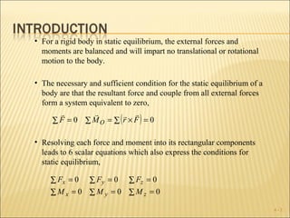
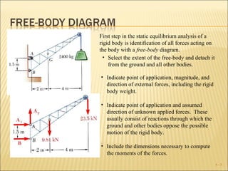


The document discusses determining the forces acting on a rigid body in static equilibrium. It provides three key points: 1) For a rigid body to be in static equilibrium, the external forces and moments acting on it must balance so there is no translational or rotational motion. 2) The conditions for static equilibrium are that the resultant force and couple from all external forces equals zero. 3) Resolving each force and moment into rectangular components provides six scalar equations that also express the static equilibrium conditions.