SlideShare a Scribd company logo
SHOP MANUAL
MASSEY-FERGUSON
MODELS
340, 350, 355, 360 AND 399
The tractor serial number is iocated in two iocations,
on the seriai number plate (Fig. 1) iocated on the right
side of the tractor and stamped on the rear axie casting
(Fig. 2). The tractor seriai number is coded to identify
the machine type, year of manufacture, week of manu-
facture (during specific year) and specific unit during
week.
The iliustration shown in Fig. 3 identifies a two-wheei-
drive 360 tractor which was the 132nd tractor manufac-
tured during the 33rd week of 1988.
Fig. I—The tractor seriai number is iocated on piate
attached to tractor right side as shown as weii as stamped
on axie housing as shown in Fig, 2.
Year of manufacture Tractor Built In Week Of
5221N33132
Machine Type Week Of Manufacture
Year of Manufacture -
' A = Jan. 1992 - Dec. 1992 R = Feb. 1990 - Dec. 1990
B = Jan. 1993 - Dec. 1993 S = Jan. 1991 - Dec. 1991
N = Feb. 1988 - Jan. 1989 U = Aug. 1986 - Jan. 1987
P = Feb. 1989 - Jan. 1990 V = Feb. 1987 - Jan. 1988
9' 2—Tractor seriai number is stamped into rear axie
housing as shown as weil as on piate shown in Fig. 1.
Numbers match on originai assembiy.
Fig. 3—The tractor seriai number identifies machine type,
year ofmanufacture, weei< ofmanufacture during specific
year, and specific unit manufactured during that weeii.
The iiiustration shown identifies a two-wheei-drive 360
tractor which was the 132nd tractor manufactured during
the 33rd weeic of 1988.
Machine lype -
5000 M-F 350 2WD 5222 M-F 360 4WD
5001 M-F 350 4WD 5309 M-F 355 2WD
5012 M-F 399 2WD 5310 M-F 355 4WD
5013 M-F 399 4WD 5747 M-F 340 4WD
5221 M-F 360 2WD 5812 M-F 340 4WD
INDEX (By Starting Paragraph)
Models
340, 350, 355,
360 and 399
BRAKES
Adjustment -
340 Models With Drum Brakes 253
Models With Disc Brakes Before
Serial Number V39466 254
Models With Disc Brakes After
Serial Number V39465 255
Disc Brake Assembly —
All Models With Disc Brakes 262
Drum Brake Assembly
340 Models With Drum Brakes 261
Fluid and Bleeding 256
Master Cylinders 257
Slave Cylinders -
340 Models With Drum Brakes 258
Models With Disc Brakes Before
Serial Number V39466 259
Models With Disc Brakes After
Serial Number V39465 260
CLUTCH (ENGINE)
Engine/Transmission Split . 152
Linkage Adjustment 151
R&R and Overhaul-
Models With Dual Clutch .153
Models With Split Torque Clutch 155
DIESEL FUEL SYSTEM
Bleeding 133
Filters 131
Fuel Lift Pump . 132
Injection Pump Specifications 145
Injector Nozzles 134
Pump Drive Gear 144
Pump Timing 142
ELECTRICAL SYSTEM
Alternator and Regulator 147
Circuit Description 149
Starter 148
Wiring Diagrams 149
ENGINE (Three-Cylinders)
Cam Followers 41
Camshaft 53
Connecting Rods and Bearings 57
Cooling System 64
Crankshaft and Bearings 58
Crankshaft Rear Oil Seal 59
Cylinder Head 37
Flywheel 60
Front End/Engine Split 35
Models
340, 350, 355,
360 and 399
ENGINE (Three Cylinders) (Cont.)
Oil Pan 61
Oil Pump 62
Piston Pins 56
Pistons, Rings and Sleeves 55
R&REngine 36
ReliefValve 63
Rocker Arms 42
Rod and Piston Units 54
Timing Gear Cover . 45
Timing Gear Housing 52
Timing Gears 46
Valve Clearance . 43
Valve Guides 39
Valve Springs 40
Valve Timing 44
Valves and Seats . 3 8
ENGINE (Six Cylinder 6.3544)
Accessory/Injection Pump Drive 81
Cam Followers 73
Camshaft 82
Connecting Rods and Bearings 86
Cooling System 93
Crankshaft and Bearings 87
Crankshaft Gear and Idler Gears 80
Crankshaft Pulley 76
Crankshaft Rear Oil Seal 88
Cylinder Head 69
Flywheel 89
Front End/Engine Split 67
Oil Pan 90
Oil Pump 91
Piston Pins 85
Pistons, Rings and Sleeves 84
R&REngine 68
ReliefValve 92
Rocker Arms 74
Rod and Piston Units 83
Timing Gear Housing 79
Timing Gears 77
Valve Clearance 75
Valve Guides 71
Valve Springs 72
Valves and Seats 70
ENGINE (Six-Cylinder 1006.6)
Cam Followers 102
Camshaft 113
Connecting Rods and Bearings 117
Cooling System 124
Crankshaft and Bearings 118
Models
340, 350, 355,
360 and 399
ENGINE (Six-Cylinder 1006.6) (Cont.)
Crankshaft Pulley . 105
Crankshaft Rear Oil Seal 119
Cylinder Head 98
Flywheel 120
Front End/Engine Split 96
Oil Pan 121
Oil Pump 122
Piston Pins 116
Pistons, Rings and Sleeves 115
R&R Engine 97
ReliefValve 123
Rocker Arms 103
Rod and Piston Units 114
Timing Gear Cover and
Front Oil Seal 106
Timing Gear Housing 112
Timing Gears 108
Timing the Gears 107
Valve Clearance 104
Valve Guides 100
Valve Springs 101
Valves and Seats 99
FRONT AXLE SYSTEM (Two-Wheel-Drive
Models)
F r o n t A x l e A s s e m b l y a n d S t e e r i n g L i n k a g e . . . . 1
FRONT-WHEEL DRIVE (Four-Wheel-Drive
Models)
Differential -
Except "Hydralock" 13
"Hydralock" 15
Drive Shaft 9
Front Drive Axle 10
Planetary Assembly 11
Steering Knuckle Housing and Wheel Hub . . . 12
Track Rod and Toe-in 8
Tractor Split -
Without Cab 17
With Cabs 18
Transfer Gearbox -
Except Twelve-Speed Shuttle 19
With Twelve-Speed Shuttle Transmission . . 20
HYDRAULIC SYSTEM
Auxiliary Hydraulic Pump 293
Auxiliary Remote Control Valves 297
Auxiliary System Pressure 294
Hydraulic Lift Pump 290
Lift Cover 285
Reservoir and Filters 275
Selector Valve 287
Tests and Adjustments 277
Troubleshooting 276
Models
340,350,355,
360 and 399
INDEPENDENT
POWER TAKE-OFF -
Hydraulic Pressure Tests 273
Left Side Cover and Control Valve 270
Output Shaft 269
Pto Clutch, Brake and Control Valve 271
Live Power Take-off 262
MAEV DRIVE BEVEL DRIVE GEARS AND
DIFFERENTIAL
Differential and Bevel Ring Gear 235
Differential Lock 237
Main Drive Bevel Gears 240
POWER TAKE-OFF
Live 263
Independent 267
REAR AXLE AND FINAL DRIVE
Drive Axle -
340 Models With Direct Drive Axle . . . . . 251
Models With Planetary Final Drive 252
Rear Axle Assembly -
Early 340 Models With Drum Brakes . . . . 242
340 Models With Disc Brakes 244
All Except 340 Models 246
Planetary Assembly -
Models With Planetary Final Drive 247
STEERING SYSTEM
Filter and Bleeding 22
Power Cylinder -
Two-Wheel-Drive With Three-Cylinder Engine 31
Two-Wheel-Drive With Six-Cylinder Engine . 32
Four-Wheel-Drive Models 33
Pump -
Models With Separate Pump 27
Models With Tandem Pump . 29
Steering Control Valve 34
System Pressure -
With Separate Steering Pump 24
With Tandem Pump 25
Troubleshooting 23
TRANSMISSION (Six-Speed Shuttle)
Countershaft (Layshaft) and Gears 204
Lubrication 194
MainshafKOutput Shaft) and Gears 203
Planetary Unit 199
Pto Input Shaft and Retainer Housing . . . . 200
Pto Lower Shaft Front Bearing and Retainer . 201
Reverse Idler Gear And Shaft 205
Shifter Rails and Forks 198
Models
340,350,355,
360 and 399
TRANSMISSION (Six Speed Shuttle) (Cont.)
Top Cover 197
Tractor Rear Split 195
Transmission Input Shaft and Shuttle Gears . . 202
Transmission Removal 196
TRANSMISSION (Eight Speed Shuttle)
Countershaft (Layshaft) and Gears 216
Lubrication 206
Mainshaft (Output Shaft) and Gears 215
Planetary Unit 211
Pto Input Shaft and Retainer Housing 212
Pto Lower Shaft Front Bearing and Retainer . 213
Reverse Idler Gear and Shaft 217
Shifter Rails and Forks 210
Top Cover 209
Tractor Rear Split 207
Transmission Input Shaft 214
Transmission Removal 208
TRANSMISSION (Eight-Speed Standard)
Countershaft (Layshaft) and Gears 168
Lubrication 157
Mainshaft (Output Shaft) and Gears 167
Planetary Unit 163
Pto Input Shaft and Retainer Housing 164
Pto Lower Shaft Front Bearing and Retainer . 165
Reverse Idler Gear and Shaft 169
Shifter Rails and Forks 162
Top Cover and Shift Levers 161
Tractor Rear Split 158
Transmission Input Shaft 166
Transmission Removal 160
TRANSMISSION (Eight-Speed Synchromesh)
Countershaft (Layshaft) and Gears 180
Lubrication 170
Mainshaft (Output Shaft) and Gears . , 179
Planetary Unit 175
Pto Input Shaft and Retainer Housing 176
Pto Lower Shaft Front Bearing and Retainer , 177
Reverse Idler Gear and Shaft 181
Shifter Rails and Forks 174
v.r Models
f 340, 350, 355,
360 and 399
TRANSMISSION (Eight-Speed
Synchromesh) (Cont,)
Top Cover 173
Tractor Rear Split 171
Transmission Input Shaft . 178
Transmission Removal 172
TRANSMISSION (Twelve-Speed Shuttle)
Forward/Reverse Shift Control Linkage . . . . 223
Lubrication 218
Main Gear Shift Lever and Selector Shaft . . . 222
Main Transmission Countershaft and Gears . 233
Main Transmission Input Shaft 231
Main Transmission Shift Rails and Forks . . . 224
Main Transmission Upper Shaft and Gears . . 232
Pto Input Shaft and Retainer Housing . . . . 229
Pto Lower Shaft Front Bearing and Retainer . 230
Range Change Lower Shaft 227
Range Change Unit Upper Shaft 225
Range Change Upper Shaft Bearing Preload . 226
Range Selector Cam 228
Reverse Idler Gear and Shaft 234
Top Cover 221
Tractor Rear Spht 219
Transmission Removal 220
TRANSMISSION (Twelve-Speed
Synchromesh)
Countershaft (Layshaft) and Grears 192
Lubrication 182
Mainshaft (Output Shaft) and Gears 191
Planetary Unit 187
Pto Input Shaft and Retainer Housing . . . . 188
Pto Lower Shaft Front Bearing and Retainer . 189
Reverse Idler Gear and Shaft 193
Shifter Rails and Forks 186
Top Cover 185
Tractor Rear Split 183
Transmission Input Shaft 190
Transmission Removal 184
TURBOCHARGER (355 and 360 Models)
Operation 128
Service 129
8
DUAL DIMENSIONS
This service manual provides specifications in both U.S. Customary and Metric (SI) systems of
measurement. The fir$t specification is given in the measuring system perceived by us to be the
preferred system when servicing a particular component, while the second specification (given in
parenthesis) is the converted measurement. For instance, a specification of 0.011 inch (0.28 mm)
would indicate that we feel the preferred measurement in this instance is the U.S. Customary system
of measurement and the Metric equivalent of 0.011 inch is 0.28 mm.
CONDENSED SERVICE DATA
GENERAL
Engine Make
Model .
Build Code
Number of Cylinders
Bore . . . . . : .
Stroke
Displacement
Compression Ratio
Firing Order
Valve Clearance (Cold) ~
Inlet 
Exhaust
Valve Face Angle -
Inlet and Exhaust
Valve Seat Angle -
Inlet and Exhaust
Injection timing - BTDC
Static
Fuel Pump -
Make
Model
Engine Low Idle, rpm . . . .
Engine High Idle, rpm . . . .
Engine Rated Speed, rpm . .
Battery Terminal Grounded .
SIZES
Crankshaft Main
Journal Diameter
340-350
AD3.152S
CE31160
16:1
0.3 mm
(0.012 in.)
16°
725-775
2470
355
Models
360 Early 399* Late 399t
Perkins -
AT3.1524
CN31187
— 3—r
91.4 mm-
(3.6 in.)
CN31185
A6.3544
TW31159
98.4 mm
(3.875 in.)
-127 mm-
(5.0 in.)
1006.6
YA31240
100 mm
(3.937 in.)
—2.5 L—
(152 cid)
-15.5:1-
•1-2-3-
5.8 L
(354 cid)
16:1
1-5-3-6-2-4
6.0 L
(365 cid)
16.5:1
1-5-3-6-2-4
- 0.2 mm -
(0.Q08 in.)
-0.3 m m -
(0.012 in.)
0.45 mm
(0.018 in.)
35°
36°
45°
46°
17°
CAV
DPA-
23° 22°
725-775^
2470
725-775
2420# 2310
2250 -2200-
Negative
- See Paragraph 58- See See
Paragraph Paragraph
87 118
9
CONDENSED SERVICE DATA (CONT.)
SIZES (Cont.)
Crankshaft Crankpin
Diameter
Camshaft Journal Diameter
Piston Pin Diameter
Valve Stem Diameter
340-350 355
See Paragraph 58-
- See Paragraph 53-
- See Paragraph 56-
See Paragraph 39-
Models
360 Early 399* Late 399t
See
Paragraph
87
See
Paragraph
82
See
Paragraph
85
See
Paragraph
70
See
Paragraph
118
See
Paragraph
113
See
Paragraph
116
See
Paragraph
99
CLEARANCES
Main Bearing
Diametral Clearance
Rod Bearing
Diametral Clearance
Camshaft Bearing
Diametral Clearance
Crankshaft End Play
Piston Skirt to
Cylinder Clearance
- See Paragraph 58-
- See Paragraph 57-
- See Paragraph 53-
- See Paragraph 58-
- See Paragraph 55-
See
Paragraph
87
See
Paragraph
86
See
Paragraph
82
See
Paragraph
87
See
Paragraph
84
See
Paragraph
118
See
Paragraph
117
See
Paragraph
113
See
Paragraph
118
See
Paragraph
115
CAPACITIES
Cooling System
Crankcase With Filter . . . .
Transmission - Without Spacer
Transmission - With Spacer
or Transfer Housing . . . .
Final Drive Rear
Planetary Hub - Each side .
Hydrostatic Steering
-9.8 L-
(10.4 qts.)
6.8 L —
(7.2 qts.)
-0.7 L-
(1.2 pints)
—43.4 L—
(11.5 gal.)
—47.4 L—
(12.5 gal.)
20.1 L
(21.2 qts.)
15.4 L
(16.2 qts.)
23 L
(24 qts.)
14.3 L
(15.2 qts.)
0.9 L 0.9 L
(5 pints) (5 pints)
1.2 L
(2.2 pints)
10
CONDENSED SERVICE DATA (CONT.)
Models
340-350 355 360 Early 399* Late399t
CAPACITIES (Cont.)
Front Drive Axle Hubs
(Each Side) 1.2 L 1.3 L
(2.3 pints) (2.6 pints)
Front Drive
Axle Housing 4.0 L 5.8 L
(1.1 gal.) (1.5 gaL)
* M-F 399 tractors before 1990 (serial number SOOOOO).
t M-F 399 tractors beginning with serial number SOlOOl (1991 and later).
t Low idle speed should be 750 rpm, high idle rpm should be 2470 rpm and static timing should be 17° BTDC for
M-F 355 models after engine serial number U796441P.
# High idle no load speed should be 2310 rpm for M-F 399 after S. N. U793030P.
Paragraphs 1-2 MASSEY-FERGUSON
FRONT AXLE SYSTEM
(TWO-WHEEL DRIVE)
FRONT AXLE ASSEMBLY AND
STEERING LINKAGE
Two-Wheel-Drive Models
1. WHEELS AND BEARINGS. To remove front
wheel hub and bearings, raise and support the front
axle extension, then unbolt and remove the tire and
wheel assembly. Remove cap (2 or 3—Fig. 4), cotter
pin (4), castellated nut (5), washer and outer bearing
cone (7). Slide the hub assembly from spindle axle
shaft. Remove dust shield (12), seal (9) and inner
bearing cone (11). Drive bearing cups (8 and 10) from
hub if renewal is required. Pack wheel bearings lib-
erally with a multi-purpose lithium based grease.
Reassemble by reversing disassembly procedure.
Tighten castellated nut (5) to a torque of 80 N.m (60
ft.-lbs.), then back nut off to the nearest hole and
install cotter pin (4). Be sure to install cap (2 or 3)
securely.
2. TRACK ROD AND TOE-IN. All models are
equipped with hydrostatic steering. On 340-360 mod-
els, a single track rod connects the left and right
steering arms which are attached to the steering
spindles. On 399 models, the two track rods are
Fig. 4—Exploded view of wheel hub typical of two-wheei-
drive modeis.
2. Hub cap
3. Hub cap
4. Cotter pin
5. Castellated nut
and tang washer
6. Hub
7. Outer bearing cone
8. Outer bearing cup
9. Seal
10. Inner bearing cup
11. Inner bearing cone
12. Dust shield
17. Wheel retaining screws
attached to each end of the hydrostatic steering rod,
which is located between the steering arms. The track
rod of all models assures that both left and right
wheels turn in unison and the distance between ends
of track rod establishes front wheel toe-in.
Ends of track rod are automotive type and should
be renewed if wear is excessive. The procedure for
removing and installing ends is self-evident. Recom-
mended toe-in is 0-5 mm (0-3/i6 inch) for all models.
Toe-in should be measured between the wheel rims
on center line of axle, parallel to ground. Rotate
wheels and remeasure to be sure that wheels are not
bent giving incorrect reading.
Distance between front wheels is adjustable to
seven different widths by relocating axle extensions
and changing length of track rod using the pre-exist-
ing attachment holes.
On 340-360 models, axle extension and hydrostatic
steering cylinder bracket retaining screws (1—Fig. 5)
should be tightened to 180-230 N.m (135-170 ft.-lbs.)
torque. Tighten track setting screw (2) to 45-55 N.m
(33-40 ft.-lbs.) torque before tightening locknut. Note
that spacers are used on the outer screws between
steering cylinder brackets and axle extensions when
axle width is at the four widest settings. To make
small toe-in adjustments, remove track adjusting
screw (2) from left end of track rod, loosen rod end
clamp bolt on right end, then turn center section of
track rod until toe-in is correct. Reinstall track ad-
justing screw (2) and tighten rod end clamp bolt to
45-55 N.m (33-41 ft.-lbs.) torque.

Fig. 5—View of axie left end typicai of 340-360 modeis.
Track adjusting screw and iock nut (2) and cyiinder
bracket and axie extension screws (1) must be properly
instaiied and tightened.
12
MODELS 340, 350, 355, 360 & 399
3
Fig, e—View of axie left end typicai of type used on 399
modeis. Right side is equipped with a similar track rod,
adjusting bolt (2) and rod end. Rod end may be locked
with damp bolt (3) as shown orjam nut.
On 399 models, axle extension retaining screws
(1—Fig. 6) should be tightened to 340-450 N.m (250-
330 ft.-lbs.) torque. Tighten track setting bolt (2) to
120-160 N.m (90-120 ft.-lbs.). To make small toe-in
adjustments, remove track adjusting bolt (2), loosen
rod end clamp bolt (3) orjam nut, then turn track rod
until toe-in is correct. Reinstall track adjusting bolt
(2) and tighten to 120-160 N.m (90-120 ft.-lbs.)
torque. Tighten rod end clamp bolt (3) to 45 N.m (33
ft.-lbs.) torque or jam nut to 160-200 N.m (120-130
Paragraphs 3-4
ft.-lbs.) torque. Equal toe-in adjustments should be
made to both sides to center steering.
3. SPINDLES, AXLE EXTENSIONS AND
BUSHINGS. To remove spindle (12—Fig. 7 or Fig.
8), first remove the wheel and hub. Disconnect rod
end (2) from steering arm (1), remove clamp screw
(13) from steering arm, then remove steering arm.
Remove key (14) and seal (20) from top of spindle,
then lower spindle out of axle extension (19). Remove
thrust bearing (11) from spindle. Clean and inspect
parts for wear or other damage and renew as neces-
sary.
Each axle extension (19) is equipped with two spin-
dle bushings that must be reamed after pressing into
position. Clean all metal particles from bore and be
sure that hole for grease fitting is clean and open
before assembling.
When reassembling, install thrust bearing (11) on
spindle so that numbered side of bearing is facing
upward and insert spindle through axle extension.
Install seal (20) and key (14) then locate steering arm
on top of spindle. Tighten steering arm retaining
clamping screw to a torque of 125-165 N.m (94-122
ft.-lbs.) for 340-360 models; 280-370 N.m (207-273
ft.-lbs.) torque for 399 models. Refer to paragraph 2
for track and toe-in adjustment and other recom-
mended torques. Balance ofreassembly is the reverse
of disassembly.
4, AXLE CENTER MEMBER, PIVOT PIN AND
BUSHINGS. To remove front axle assembly, first
remove any front mounted equipment, guards,
weights and weight frame. Raise front of tractor in
such a way that it will not interfere with the removal
•
Fig. 7^Exploded view of front axie typical
of two-wheei'drive 340-360 models.
1. Steering arm
2. Rod end
3. Cylinder pivot pin
4. Axle pivot pin
5. Steering cylinder
6. Track rod
7. Thrust washer
8. Steering cylinder bracket
9. Tapered retaining pin
10. Axle center member
11. Thrust washers
12. Spindle
18. Bushing
19. Axle extension
20. Seal
21. Shims
13
Paragraph 4 (Cont.) MASSEY-FERGUSON
21
Fig. 8—Exploded view of front axie
typicai of type used on two-wheei-
drive 399 modeis.
1. Steering arm
2. Rod end
3. Cylinder ball joint
4. Axle pivot pin
5. Steering cylinder
6. Track rod
7. Thrust washer
8. Pivot block
9. Retaining pin
10. Axle center member
11. Thrust washers
12. Spindle
14. Key
18. Bushing
19. Axle extension
20. Seal
21. Shims
22. Bushing
23. Shims
24. Pivot pin
25. Hydraulic hoses
26. Jam nut
Fig. 9—Axie pivot bushings should be installed as shown
for 340-360 models. Hole (B) shouid be aiigned with
grease passage and siot (C) should be in position indi-
cated.
of the axle, such as with a support located under
engine sump. Removal of wheels, spindles and axle
extensions will reduce weight and may make han-
dling the center member easier; however, the com-
plete axle assembly can be removed as a unit.
Disconnect hydrostatic steering hoses from the steer-
ing cylinder or cylinders and cover openings to pre-
vent the entry ofdirt. Support the axle with a suitable
jack to prevent tipping while permitting the axle to
be lowered and moved safely. Remove retaining pin
(9—Fig. 7 or Fig. 8), then use a suitable puller to
withdraw axle pivot pin (4). Carefully lower the axle
assembly and roll axle from under tractor.
Check axle pivot bushings and renew if necessary.
Bushings are located in support housing of 340-360
models and should be installed fiush to 0.5 mm (0.020
inch) below fiush (A—Fig. 9) with housing bore. Split
(Fig. 9) in bushing should be down and hole (B) for
grease passage should be up as shown. Axle pivot
bushings (22—Fig. 8) are located in axle of 399 mod-
els. On all models, it may be necessary to ream bushings
after installation. Reverse removal procedure when
assembling. Axle end play should be 0.05-0.25 mm
(0.002-0.010 inch) on pivot pin. Push the axle toward
rear on pivot pin, then measure axle end play with a
feeler gauge as shown in Fig. 10 or Fig. 11. Shims
(21—Fig. 7 or Fig. 8) are available in various thick-
14
Thank you very much for
your reading. Please Click
Here. Then Get COMPLETE
MANUAL. NO WAITING
NOTE:
If there is no response to
click on the link above,
please download the PDF
document first and then
click on it.
MODELS 340, 350, 355, 360 & 399 Paragraph 5
Fig. 10—End play of front axle shouid be measured with
a feeiergauge as shown for 340-360 modei with two-wheel
drive.
Fig. 11—Measure endplay of front axle with a feeiergauge
as shown for model 399 with two-wheel drive.
nesses for adjusting end play. On 340-360 models,
make sure that tapered pin (9—Fig. 7) is correctly
and firmly seated, then tighten retaining nut to 80-
140 N.m (70-110ft.-lbs.)torque. On all models, refer
to paragraphs 2 and 3 for additional torque values
and assembly notes.
5. FRONT SUPPORT. To remove the front sup-
port, the axle must be removed, the radiator must be
I removed and the front support must be unbolted from
the front of engine. The front axle, the front support
and the remainder of the tractor must each be sup-
ported separately while removing, while separated
Fig. 12—Measure gap (A) between the top spacer tube on
right side and front support of 340-360 models.
and while assembling. Be sure that sufficient equip-
ment is available before beginning.
To remove front axle support from 340-360 models,
first remove any front mounted equipment, guards,
weights and weight frame. Remove grille, hood, hood
side panels, air cleaner and battery. Drain cooling
system, disconnect radiator hoses and disconnect
wires to headlights. Remove radiator and oil cooler
assembly, then refer to paragraph 4 and remove the
axle assembly. Attach a hoist or other supporting
device to the front support, then unbolt and separate
the front support from the front of the engine. Be
careful not to lose shims which may be located be-
tween front support casting and front of engine.
To remove front axle support from 399 models, first
remove any front mounted equipment, guards,
weights and weight frame. Remove fuel tank and
radiator and radiator support frame, then refer to
paragraph 4 and remove the axle assembly. Attach a
hoist or other supporting device to the front support,
then unbolt and separate the front support from the
front ofthe engine. Be careful not to lose shims which
may be located between front support casting and
front of engine.
Reattach front support to engine of all models by
reversing the removal procedure, but omitting any
shims originally installed between support and en-
gine. On 340-360 models, tighten the retaining
screws to 240-320 N.m (177-236 ft.-lbs.) torque.
Measure any gap (A—Fig. 12) between the top spacer
tube on right side and front support with a feeler
gauge. Loosen retaining screws and install shims
equal to the measured gap plus 0.13 mm (0.005 inch).
15
Paragraphs 7-9 MASSEY-FERGUSON
Fig. 13—Use a feeler gauge to measure gap (A) between
the lower ears of casting and spacer tubes for 399 models.
Tighten screws retaining front support of 399 mod-
els to 230-255 N.m (170-190 ft.-lbs.) torque. Use a
feeler gauge to measure any gap between the lower
ears of front support casting and spacer tubes of 399
models as shown in Fig. 13. Loosen retaining screws
and install shims equal to the measured gap plus 0.13
mm (0.005 inch).
On all models, complete assembly by reversing the
removal procedure.
FRONT-WHEEL DRIVE
7. A mechanical front-wheel drive is available on
these models. There are some differences between the
Front-Wheel Drive Systems used on these models
that will be referred to in the servicing instructions
which follow.
The front drive is engaged by an electric sole-
noid/hydraulic valve which directs oil pressure to
move a dog clutch or by a dog clutch which is moved
manually by shift fork by way of mechanical linkage.
The transfer gearbox is attached to the left side of the
range gearbox of models with twelve-speed shuttle
transmissions or located between the rear of the
transniission housing and the front of the rear axle
housing of other models. On all models, a drive shaft
with two "U" joints connects the transfer gearbox to
front axle.
TRACK ROD AND TOE-IN
All Four-Wheel-Drive Models
8. All models are equipped with hydrostatic steer-
ing. A single track rod connects the left and right
steering arms which are attached to the steering
spindles. The track rod assures that both left and
right wheels turn in unison, and the distance between
ends of track rod establishes front wheel toe-in.
Ends of track rod are automotive type and should
be renewed if wear is excessive. The procedure for
removing and installing ends is self-evident. Recom-
mended toe-in is 0 for all models. Toe-in should be
measured between the wheel rims on center line of
axle, parallel to ground. Rotate wheels and remeas-
ure to be sure that wheels are not bent giving incor-
rect reading.
Distance between front wheels is adjustable to
different widths by relocating the wheel on the center
disc or by reversing the wheels. If wheels are re-
versed, they must be moved to opposite sides of trac-
tor to maintain correct tire tread direction.
To adjust toe-in, loosen the locknuts at each end of
the track (tie) rod, then turn the tie rod tube to set
the toe-in. Tighten locknuts at each end when adjust-
ment is correct. Nut retaining ball-joint of track rod
end in the steering arm should be tightened to 78-86
N.m (58-63 ft.-lbs.) torque for 340-360 models, 108-
118 N.m (80-87 ft.-lbs.) torque for 399 models.
DRIVE SHAFT
All Models So Equipped
9. REMOVE AND REINSTALL. To remove drive
shaft, first loosen clamps (1 and 2—Fig. 14), then
slide guard (3) into the center tube. Remove spring
clip (6) from guard at front. Remove bolts (4 and 5)
from ends, then remove the shield and drive shaft
assembly. Unscrew seal retaining ring from the slid-
ing coupling, remove sliding coupling from rear end
4
16
MODELS 340, 350, 355, 360 & 399 Paragraphs 10-11
1 3
7 5
Fig. 14—View showing both ends of drive shaft and
shield. Front (axie) end of shield is retained by dip (6).
1. Clamp
2. Clamp 5. Retaining bolts
3. Guard 6. Clip
4. Retaining bolts 7. Clamp
of drive shaft, then remove drive shaft from guard
tube.
When reassembling, grease splines of sliding cou-
pling and both universal joints. Insert the long sec-
tion of drive shaft into guard, then assemble sliding
coupling at rear, making sure that arrows on drive
shaft and sliding coupling are aligned. Coat threads
ofbolts (4 and 5) with "Loctite 270," then attach drive
shaft fianges with bolts (4 and 5) tightened to 55-75
N.m (40-55 ft.-lbs.) torque. Install clip (6) at front
(axle end), making sure that drain hole in guard is
toward bottom. Distance from step in axle and front
ofguard should be approximately 90 mm (3.5 inches).
FRONT DRIVE AXLE
All Models So Equipped
10. R&R ASSEMBLY First remove the drive
shaft and shield as outlined in paragraph 9. Raise
front of tractor in such a way that it will not interfere
with the removal of the axle. Remove front wheels
and weights, then support the axle with a suitable
jack or special safety stand to prevent tipping while
permitting the axle to be lowered and moved safely.
Disconnect hoses from the steering cylinder and cover
openings to prevent the entry of dirt. Remove retain-
ing pin or screw from the front pivot, then use a
suitable puller to withdraw axle pivot pin. Lower axle
until free, then carefully roll axle away.
Reinstall front drive axle by reversing the removal
procedure. A spacer is located at the rear of the axle
pivot and sufficient thickness of shims should be
located in front of axle to reduce end play to 0.05-0.25
mm (0.002-0.010 inch). Grease pivot after correct
thickness of shims and pivot pin retaining screw or
pin have been installed.
PLANETARY ASSEMBLY
All Models So Equipped
11. R&R AND OVERHAUL. Refer to Fig. 15.
Either planetary assembly can be serviced without
Fig. IS^Cross section of typical front
drive axle.
17

More Related Content

What's hot

Valtra Valmet 6850 TRACTOR Service Repair Manual
Valtra Valmet 6850 TRACTOR Service Repair ManualValtra Valmet 6850 TRACTOR Service Repair Manual
Valtra Valmet 6850 TRACTOR Service Repair Manual
jkdjksmde
 
Ford 1700 tractor service repair manual
Ford 1700 tractor service repair manualFord 1700 tractor service repair manual
Ford 1700 tractor service repair manual
jkmsedopl
 
Hyster c177 (h2.50 xl europe) forklift service repair manual
Hyster c177 (h2.50 xl europe) forklift service repair manualHyster c177 (h2.50 xl europe) forklift service repair manual
Hyster c177 (h2.50 xl europe) forklift service repair manual
fjskefkksem
 
Valtra T 140 TRACTOR Service Repair Manual
Valtra T 140 TRACTOR Service Repair ManualValtra T 140 TRACTOR Service Repair Manual
Valtra T 140 TRACTOR Service Repair Manual
jkmdmm mkueoi
 
Caterpillar cat 966 c wheel loader (prefix 76j) service repair manual (76j063...
Caterpillar cat 966 c wheel loader (prefix 76j) service repair manual (76j063...Caterpillar cat 966 c wheel loader (prefix 76j) service repair manual (76j063...
Caterpillar cat 966 c wheel loader (prefix 76j) service repair manual (76j063...
fjjskmdmem
 
Massey ferguson mf290 xtra tractors (india) parts catalogue manual
Massey ferguson mf290 xtra tractors (india) parts catalogue manualMassey ferguson mf290 xtra tractors (india) parts catalogue manual
Massey ferguson mf290 xtra tractors (india) parts catalogue manual
udjjjskkdmme
 
MASSEY FERGUSON MF362 TRACTOR Service Repair Manual
MASSEY FERGUSON MF362 TRACTOR Service Repair ManualMASSEY FERGUSON MF362 TRACTOR Service Repair Manual
MASSEY FERGUSON MF362 TRACTOR Service Repair Manual
fusjfjjekdmmemd
 

What's hot (20)

Torques diesel
Torques dieselTorques diesel
Torques diesel
 
Massey Ferguson Mf 8450, 8460 tractor (tier 3) parts catalog
Massey Ferguson Mf 8450, 8460 tractor (tier 3) parts catalogMassey Ferguson Mf 8450, 8460 tractor (tier 3) parts catalog
Massey Ferguson Mf 8450, 8460 tractor (tier 3) parts catalog
 
Massey Ferguson MF 8650 tractor parts catalog
Massey Ferguson MF 8650 tractor parts catalog Massey Ferguson MF 8650 tractor parts catalog
Massey Ferguson MF 8650 tractor parts catalog
 
Volvo g780 b motor grader service repair manual
Volvo g780 b motor grader service repair manualVolvo g780 b motor grader service repair manual
Volvo g780 b motor grader service repair manual
 
Valtra Valmet 6850 TRACTOR Service Repair Manual
Valtra Valmet 6850 TRACTOR Service Repair ManualValtra Valmet 6850 TRACTOR Service Repair Manual
Valtra Valmet 6850 TRACTOR Service Repair Manual
 
Car service-repair-manuals
Car service-repair-manualsCar service-repair-manuals
Car service-repair-manuals
 
Jys casting for metso hp200 cone crusher parts
Jys casting for metso hp200 cone crusher partsJys casting for metso hp200 cone crusher parts
Jys casting for metso hp200 cone crusher parts
 
MF4283
MF4283MF4283
MF4283
 
Massey Ferguson MF 8470, 8480 (tier 3) parts catalog
Massey Ferguson MF 8470, 8480 (tier 3) parts catalog Massey Ferguson MF 8470, 8480 (tier 3) parts catalog
Massey Ferguson MF 8470, 8480 (tier 3) parts catalog
 
Still r70 30 fork truck service repair manual
Still r70 30 fork truck service repair manualStill r70 30 fork truck service repair manual
Still r70 30 fork truck service repair manual
 
Ford 1700 tractor service repair manual
Ford 1700 tractor service repair manualFord 1700 tractor service repair manual
Ford 1700 tractor service repair manual
 
Jys casting for metso hp100 cone crusher parts
Jys casting for metso hp100 cone crusher partsJys casting for metso hp100 cone crusher parts
Jys casting for metso hp100 cone crusher parts
 
Hyster c177 (h2.50 xl europe) forklift service repair manual
Hyster c177 (h2.50 xl europe) forklift service repair manualHyster c177 (h2.50 xl europe) forklift service repair manual
Hyster c177 (h2.50 xl europe) forklift service repair manual
 
Valtra T 140 TRACTOR Service Repair Manual
Valtra T 140 TRACTOR Service Repair ManualValtra T 140 TRACTOR Service Repair Manual
Valtra T 140 TRACTOR Service Repair Manual
 
Volvo ec210 b lc ec210blc excavator service repair manual
Volvo ec210 b lc ec210blc excavator service repair manualVolvo ec210 b lc ec210blc excavator service repair manual
Volvo ec210 b lc ec210blc excavator service repair manual
 
Caterpillar cat 966 c wheel loader (prefix 76j) service repair manual (76j063...
Caterpillar cat 966 c wheel loader (prefix 76j) service repair manual (76j063...Caterpillar cat 966 c wheel loader (prefix 76j) service repair manual (76j063...
Caterpillar cat 966 c wheel loader (prefix 76j) service repair manual (76j063...
 
Massey Ferguson MF 9240 parts catalog
Massey Ferguson MF 9240 parts catalog Massey Ferguson MF 9240 parts catalog
Massey Ferguson MF 9240 parts catalog
 
Merkel v packings_v-1000
Merkel v packings_v-1000Merkel v packings_v-1000
Merkel v packings_v-1000
 
Massey ferguson mf290 xtra tractors (india) parts catalogue manual
Massey ferguson mf290 xtra tractors (india) parts catalogue manualMassey ferguson mf290 xtra tractors (india) parts catalogue manual
Massey ferguson mf290 xtra tractors (india) parts catalogue manual
 
MASSEY FERGUSON MF362 TRACTOR Service Repair Manual
MASSEY FERGUSON MF362 TRACTOR Service Repair ManualMASSEY FERGUSON MF362 TRACTOR Service Repair Manual
MASSEY FERGUSON MF362 TRACTOR Service Repair Manual
 

Similar to Massey ferguson mf399 tractor service repair manual

MASSEY FERGUSON MF390T TRACTOR Service Repair Manual
MASSEY FERGUSON MF390T TRACTOR Service Repair ManualMASSEY FERGUSON MF390T TRACTOR Service Repair Manual
MASSEY FERGUSON MF390T TRACTOR Service Repair Manual
jkksejkdm
 
MASSEY FERGUSON MF362 TRACTOR Service Repair Manual
MASSEY FERGUSON MF362 TRACTOR Service Repair ManualMASSEY FERGUSON MF362 TRACTOR Service Repair Manual
MASSEY FERGUSON MF362 TRACTOR Service Repair Manual
hskmdmjeiid
 
MASSEY FERGUSON MF383 TRACTOR Service Repair Manual
MASSEY FERGUSON MF383 TRACTOR Service Repair ManualMASSEY FERGUSON MF383 TRACTOR Service Repair Manual
MASSEY FERGUSON MF383 TRACTOR Service Repair Manual
hjskejdm
 
MASSEY FERGUSON MF365 TRACTOR Service Repair Manual
MASSEY FERGUSON MF365 TRACTOR Service Repair ManualMASSEY FERGUSON MF365 TRACTOR Service Repair Manual
MASSEY FERGUSON MF365 TRACTOR Service Repair Manual
hjdksendds
 
Case IH Case International 1896 Tractor Service Repair Manual.pdf
Case IH Case International 1896 Tractor Service Repair Manual.pdfCase IH Case International 1896 Tractor Service Repair Manual.pdf
Case IH Case International 1896 Tractor Service Repair Manual.pdf
fjdkksmemd
 
Case IH Case International 2096 Tractor Service Repair Manual.pdf
Case IH Case International 2096 Tractor Service Repair Manual.pdfCase IH Case International 2096 Tractor Service Repair Manual.pdf
Case IH Case International 2096 Tractor Service Repair Manual.pdf
fjdkksmemd
 
Case ih case international 1896 tractor service repair manual
Case ih case international 1896 tractor service repair manualCase ih case international 1896 tractor service repair manual
Case ih case international 1896 tractor service repair manual
fhsjekdmme
 
Case ih case international 1896 tractor service repair manual
Case ih case international 1896 tractor service repair manualCase ih case international 1896 tractor service repair manual
Case ih case international 1896 tractor service repair manual
fhjskemme
 
Case ih case international 1896 tractor service repair manual
Case ih case international 1896 tractor service repair manualCase ih case international 1896 tractor service repair manual
Case ih case international 1896 tractor service repair manual
fujskekfmsme
 

Similar to Massey ferguson mf399 tractor service repair manual (18)

Massey ferguson mf375 tractor service repair manual
Massey ferguson mf375 tractor service repair manualMassey ferguson mf375 tractor service repair manual
Massey ferguson mf375 tractor service repair manual
 
MASSEY FERGUSON MF390T TRACTOR Service Repair Manual
MASSEY FERGUSON MF390T TRACTOR Service Repair ManualMASSEY FERGUSON MF390T TRACTOR Service Repair Manual
MASSEY FERGUSON MF390T TRACTOR Service Repair Manual
 
Massey ferguson mf390 t tractor service repair manual
Massey ferguson mf390 t tractor service repair manualMassey ferguson mf390 t tractor service repair manual
Massey ferguson mf390 t tractor service repair manual
 
MASSEY FERGUSON MF362 TRACTOR Service Repair Manual
MASSEY FERGUSON MF362 TRACTOR Service Repair ManualMASSEY FERGUSON MF362 TRACTOR Service Repair Manual
MASSEY FERGUSON MF362 TRACTOR Service Repair Manual
 
Massey ferguson mf362 tractor service repair manual
Massey ferguson mf362 tractor service repair manualMassey ferguson mf362 tractor service repair manual
Massey ferguson mf362 tractor service repair manual
 
Massey ferguson mf365 tractor service repair manual
Massey ferguson mf365 tractor service repair manualMassey ferguson mf365 tractor service repair manual
Massey ferguson mf365 tractor service repair manual
 
Massey ferguson mf383 tractor service repair manual
Massey ferguson mf383 tractor service repair manualMassey ferguson mf383 tractor service repair manual
Massey ferguson mf383 tractor service repair manual
 
MASSEY FERGUSON MF383 TRACTOR Service Repair Manual
MASSEY FERGUSON MF383 TRACTOR Service Repair ManualMASSEY FERGUSON MF383 TRACTOR Service Repair Manual
MASSEY FERGUSON MF383 TRACTOR Service Repair Manual
 
MASSEY FERGUSON MF365 TRACTOR Service Repair Manual
MASSEY FERGUSON MF365 TRACTOR Service Repair ManualMASSEY FERGUSON MF365 TRACTOR Service Repair Manual
MASSEY FERGUSON MF365 TRACTOR Service Repair Manual
 
Massey ferguson mf398 tractor service repair manual
Massey ferguson mf398 tractor service repair manualMassey ferguson mf398 tractor service repair manual
Massey ferguson mf398 tractor service repair manual
 
Ford 7840 tractor service repair manual
Ford 7840 tractor service repair manualFord 7840 tractor service repair manual
Ford 7840 tractor service repair manual
 
Ford 5640 tractor service repair manual
Ford 5640 tractor service repair manualFord 5640 tractor service repair manual
Ford 5640 tractor service repair manual
 
Ford 6640 tractor service repair manual
Ford 6640 tractor service repair manualFord 6640 tractor service repair manual
Ford 6640 tractor service repair manual
 
Case IH Case International 1896 Tractor Service Repair Manual.pdf
Case IH Case International 1896 Tractor Service Repair Manual.pdfCase IH Case International 1896 Tractor Service Repair Manual.pdf
Case IH Case International 1896 Tractor Service Repair Manual.pdf
 
Case IH Case International 2096 Tractor Service Repair Manual.pdf
Case IH Case International 2096 Tractor Service Repair Manual.pdfCase IH Case International 2096 Tractor Service Repair Manual.pdf
Case IH Case International 2096 Tractor Service Repair Manual.pdf
 
Case ih case international 1896 tractor service repair manual
Case ih case international 1896 tractor service repair manualCase ih case international 1896 tractor service repair manual
Case ih case international 1896 tractor service repair manual
 
Case ih case international 1896 tractor service repair manual
Case ih case international 1896 tractor service repair manualCase ih case international 1896 tractor service repair manual
Case ih case international 1896 tractor service repair manual
 
Case ih case international 1896 tractor service repair manual
Case ih case international 1896 tractor service repair manualCase ih case international 1896 tractor service repair manual
Case ih case international 1896 tractor service repair manual
 

More from fhhsjdkmem

Caterpillar cat 324 d l excavator (prefix tsn) service repair manual (tsn0000...
Caterpillar cat 324 d l excavator (prefix tsn) service repair manual (tsn0000...Caterpillar cat 324 d l excavator (prefix tsn) service repair manual (tsn0000...
Caterpillar cat 324 d l excavator (prefix tsn) service repair manual (tsn0000...
fhhsjdkmem
 
Caterpillar cat 324 d l excavator (prefix trh) service repair manual (trh0000...
Caterpillar cat 324 d l excavator (prefix trh) service repair manual (trh0000...Caterpillar cat 324 d l excavator (prefix trh) service repair manual (trh0000...
Caterpillar cat 324 d l excavator (prefix trh) service repair manual (trh0000...
fhhsjdkmem
 
Caterpillar cat 324 d l excavator (prefix t2d) service repair manual (t2d0000...
Caterpillar cat 324 d l excavator (prefix t2d) service repair manual (t2d0000...Caterpillar cat 324 d l excavator (prefix t2d) service repair manual (t2d0000...
Caterpillar cat 324 d l excavator (prefix t2d) service repair manual (t2d0000...
fhhsjdkmem
 
Caterpillar cat 324 d l excavator (prefix pyt) service repair manual (pyt0000...
Caterpillar cat 324 d l excavator (prefix pyt) service repair manual (pyt0000...Caterpillar cat 324 d l excavator (prefix pyt) service repair manual (pyt0000...
Caterpillar cat 324 d l excavator (prefix pyt) service repair manual (pyt0000...
fhhsjdkmem
 
Caterpillar cat 324 d l excavator (prefix mnd) service repair manual (mnd0000...
Caterpillar cat 324 d l excavator (prefix mnd) service repair manual (mnd0000...Caterpillar cat 324 d l excavator (prefix mnd) service repair manual (mnd0000...
Caterpillar cat 324 d l excavator (prefix mnd) service repair manual (mnd0000...
fhhsjdkmem
 
Caterpillar cat 324 d l excavator (prefix sym) service repair manual (sym0000...
Caterpillar cat 324 d l excavator (prefix sym) service repair manual (sym0000...Caterpillar cat 324 d l excavator (prefix sym) service repair manual (sym0000...
Caterpillar cat 324 d l excavator (prefix sym) service repair manual (sym0000...
fhhsjdkmem
 
Caterpillar cat 324 d l excavator (prefix lab) service repair manual (lab0000...
Caterpillar cat 324 d l excavator (prefix lab) service repair manual (lab0000...Caterpillar cat 324 d l excavator (prefix lab) service repair manual (lab0000...
Caterpillar cat 324 d l excavator (prefix lab) service repair manual (lab0000...
fhhsjdkmem
 
Crown wd2300 s series walkie reach stacker service repair manual
Crown wd2300 s series walkie reach stacker service repair manualCrown wd2300 s series walkie reach stacker service repair manual
Crown wd2300 s series walkie reach stacker service repair manual
fhhsjdkmem
 
Crown tsp6000 series turret order picker service repair manual
Crown tsp6000 series turret order picker service repair manualCrown tsp6000 series turret order picker service repair manual
Crown tsp6000 series turret order picker service repair manual
fhhsjdkmem
 
Crown sp3400 (four point) series forklift service repair manual
Crown sp3400 (four point) series forklift service repair manualCrown sp3400 (four point) series forklift service repair manual
Crown sp3400 (four point) series forklift service repair manual
fhhsjdkmem
 
Caterpillar cat 324 e l excavator (prefix kte) service repair manual (kte0000...
Caterpillar cat 324 e l excavator (prefix kte) service repair manual (kte0000...Caterpillar cat 324 e l excavator (prefix kte) service repair manual (kte0000...
Caterpillar cat 324 e l excavator (prefix kte) service repair manual (kte0000...
fhhsjdkmem
 

More from fhhsjdkmem (20)

Caterpillar cat 324 d l excavator (prefix tsn) service repair manual (tsn0000...
Caterpillar cat 324 d l excavator (prefix tsn) service repair manual (tsn0000...Caterpillar cat 324 d l excavator (prefix tsn) service repair manual (tsn0000...
Caterpillar cat 324 d l excavator (prefix tsn) service repair manual (tsn0000...
 
Caterpillar cat 324 d l excavator (prefix trh) service repair manual (trh0000...
Caterpillar cat 324 d l excavator (prefix trh) service repair manual (trh0000...Caterpillar cat 324 d l excavator (prefix trh) service repair manual (trh0000...
Caterpillar cat 324 d l excavator (prefix trh) service repair manual (trh0000...
 
Caterpillar cat 324 d l excavator (prefix t2d) service repair manual (t2d0000...
Caterpillar cat 324 d l excavator (prefix t2d) service repair manual (t2d0000...Caterpillar cat 324 d l excavator (prefix t2d) service repair manual (t2d0000...
Caterpillar cat 324 d l excavator (prefix t2d) service repair manual (t2d0000...
 
Caterpillar cat 324 d l excavator (prefix pyt) service repair manual (pyt0000...
Caterpillar cat 324 d l excavator (prefix pyt) service repair manual (pyt0000...Caterpillar cat 324 d l excavator (prefix pyt) service repair manual (pyt0000...
Caterpillar cat 324 d l excavator (prefix pyt) service repair manual (pyt0000...
 
Caterpillar cat 324 d l excavator (prefix mnd) service repair manual (mnd0000...
Caterpillar cat 324 d l excavator (prefix mnd) service repair manual (mnd0000...Caterpillar cat 324 d l excavator (prefix mnd) service repair manual (mnd0000...
Caterpillar cat 324 d l excavator (prefix mnd) service repair manual (mnd0000...
 
Caterpillar cat 324 d l excavator (prefix sym) service repair manual (sym0000...
Caterpillar cat 324 d l excavator (prefix sym) service repair manual (sym0000...Caterpillar cat 324 d l excavator (prefix sym) service repair manual (sym0000...
Caterpillar cat 324 d l excavator (prefix sym) service repair manual (sym0000...
 
Caterpillar cat 324 d l excavator (prefix lab) service repair manual (lab0000...
Caterpillar cat 324 d l excavator (prefix lab) service repair manual (lab0000...Caterpillar cat 324 d l excavator (prefix lab) service repair manual (lab0000...
Caterpillar cat 324 d l excavator (prefix lab) service repair manual (lab0000...
 
Crown wf3000 series forklift service repair manual
Crown wf3000 series forklift service repair manualCrown wf3000 series forklift service repair manual
Crown wf3000 series forklift service repair manual
 
Crown we2000 series forklift service repair manual
Crown we2000 series forklift service repair manualCrown we2000 series forklift service repair manual
Crown we2000 series forklift service repair manual
 
Crown wd2300 s series walkie reach stacker service repair manual
Crown wd2300 s series walkie reach stacker service repair manualCrown wd2300 s series walkie reach stacker service repair manual
Crown wd2300 s series walkie reach stacker service repair manual
 
Crown wave50 work assit vehicle service repair manual
Crown wave50 work assit vehicle service repair manualCrown wave50 work assit vehicle service repair manual
Crown wave50 work assit vehicle service repair manual
 
Crown tsp6000 series turret order picker service repair manual
Crown tsp6000 series turret order picker service repair manualCrown tsp6000 series turret order picker service repair manual
Crown tsp6000 series turret order picker service repair manual
 
Crown st3000 series forklift service repair manual
Crown st3000 series forklift service repair manualCrown st3000 series forklift service repair manual
Crown st3000 series forklift service repair manual
 
Crown sp3400 series forklift service repair manual
Crown sp3400 series forklift service repair manualCrown sp3400 series forklift service repair manual
Crown sp3400 series forklift service repair manual
 
Crown sp3400 (four point) series forklift service repair manual
Crown sp3400 (four point) series forklift service repair manualCrown sp3400 (four point) series forklift service repair manual
Crown sp3400 (four point) series forklift service repair manual
 
Crown sc3200 series forklift service repair manual
Crown sc3200 series forklift service repair manualCrown sc3200 series forklift service repair manual
Crown sc3200 series forklift service repair manual
 
Crown sc3018 forklift service repair manual
Crown sc3018 forklift service repair manualCrown sc3018 forklift service repair manual
Crown sc3018 forklift service repair manual
 
Crown sc3016 forklift service repair manual
Crown sc3016 forklift service repair manualCrown sc3016 forklift service repair manual
Crown sc3016 forklift service repair manual
 
Crown sc3013 forklift service repair manual
Crown sc3013 forklift service repair manualCrown sc3013 forklift service repair manual
Crown sc3013 forklift service repair manual
 
Caterpillar cat 324 e l excavator (prefix kte) service repair manual (kte0000...
Caterpillar cat 324 e l excavator (prefix kte) service repair manual (kte0000...Caterpillar cat 324 e l excavator (prefix kte) service repair manual (kte0000...
Caterpillar cat 324 e l excavator (prefix kte) service repair manual (kte0000...
 

Recently uploaded

一比一原版SDSU毕业证圣地亚哥州立大学毕业证成绩单如何办理
一比一原版SDSU毕业证圣地亚哥州立大学毕业证成绩单如何办理一比一原版SDSU毕业证圣地亚哥州立大学毕业证成绩单如何办理
一比一原版SDSU毕业证圣地亚哥州立大学毕业证成绩单如何办理
psavhef
 
一比一原版BC毕业证波士顿学院毕业证成绩单如何办理
一比一原版BC毕业证波士顿学院毕业证成绩单如何办理一比一原版BC毕业证波士顿学院毕业证成绩单如何办理
一比一原版BC毕业证波士顿学院毕业证成绩单如何办理
amvovau
 
The Future of Autonomous Vehicles | civilthings.com | Detailed information
The Future of Autonomous Vehicles | civilthings.com |  Detailed informationThe Future of Autonomous Vehicles | civilthings.com |  Detailed information
The Future of Autonomous Vehicles | civilthings.com | Detailed information
gettygaming1
 

Recently uploaded (10)

Core technology of Hyundai Motor Group's EV platform 'E-GMP'
Core technology of Hyundai Motor Group's EV platform 'E-GMP'Core technology of Hyundai Motor Group's EV platform 'E-GMP'
Core technology of Hyundai Motor Group's EV platform 'E-GMP'
 
Essential Maintenance Tips For Commercial Vans.
Essential Maintenance Tips For Commercial Vans.Essential Maintenance Tips For Commercial Vans.
Essential Maintenance Tips For Commercial Vans.
 
一比一原版SDSU毕业证圣地亚哥州立大学毕业证成绩单如何办理
一比一原版SDSU毕业证圣地亚哥州立大学毕业证成绩单如何办理一比一原版SDSU毕业证圣地亚哥州立大学毕业证成绩单如何办理
一比一原版SDSU毕业证圣地亚哥州立大学毕业证成绩单如何办理
 
gtyccccccccccccccccccccccccccccccccccccccccccccccccccccccc
gtycccccccccccccccccccccccccccccccccccccccccccccccccccccccgtyccccccccccccccccccccccccccccccccccccccccccccccccccccccc
gtyccccccccccccccccccccccccccccccccccccccccccccccccccccccc
 
Tyre Industrymarket overview with examples of CEAT
Tyre Industrymarket overview with examples of CEATTyre Industrymarket overview with examples of CEAT
Tyre Industrymarket overview with examples of CEAT
 
一比一原版BC毕业证波士顿学院毕业证成绩单如何办理
一比一原版BC毕业证波士顿学院毕业证成绩单如何办理一比一原版BC毕业证波士顿学院毕业证成绩单如何办理
一比一原版BC毕业证波士顿学院毕业证成绩单如何办理
 
Wondering if Your Mercedes EIS is at Fault Here’s How to Tell
Wondering if Your Mercedes EIS is at Fault Here’s How to TellWondering if Your Mercedes EIS is at Fault Here’s How to Tell
Wondering if Your Mercedes EIS is at Fault Here’s How to Tell
 
Why Isn't Your BMW X5's Comfort Access Functioning Properly Find Out Here
Why Isn't Your BMW X5's Comfort Access Functioning Properly Find Out HereWhy Isn't Your BMW X5's Comfort Access Functioning Properly Find Out Here
Why Isn't Your BMW X5's Comfort Access Functioning Properly Find Out Here
 
Advanced Technology for Auto Part Industry Inventory Solutions
Advanced Technology for Auto Part Industry Inventory SolutionsAdvanced Technology for Auto Part Industry Inventory Solutions
Advanced Technology for Auto Part Industry Inventory Solutions
 
The Future of Autonomous Vehicles | civilthings.com | Detailed information
The Future of Autonomous Vehicles | civilthings.com |  Detailed informationThe Future of Autonomous Vehicles | civilthings.com |  Detailed information
The Future of Autonomous Vehicles | civilthings.com | Detailed information
 

Massey ferguson mf399 tractor service repair manual

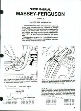
  • 1. SHOP MANUAL MASSEY-FERGUSON MODELS 340, 350, 355, 360 AND 399 The tractor serial number is iocated in two iocations, on the seriai number plate (Fig. 1) iocated on the right side of the tractor and stamped on the rear axie casting (Fig. 2). The tractor seriai number is coded to identify the machine type, year of manufacture, week of manu- facture (during specific year) and specific unit during week. The iliustration shown in Fig. 3 identifies a two-wheei- drive 360 tractor which was the 132nd tractor manufac- tured during the 33rd week of 1988. Fig. I—The tractor seriai number is iocated on piate attached to tractor right side as shown as weii as stamped on axie housing as shown in Fig, 2. Year of manufacture Tractor Built In Week Of 5221N33132 Machine Type Week Of Manufacture Year of Manufacture - ' A = Jan. 1992 - Dec. 1992 R = Feb. 1990 - Dec. 1990 B = Jan. 1993 - Dec. 1993 S = Jan. 1991 - Dec. 1991 N = Feb. 1988 - Jan. 1989 U = Aug. 1986 - Jan. 1987 P = Feb. 1989 - Jan. 1990 V = Feb. 1987 - Jan. 1988 9' 2—Tractor seriai number is stamped into rear axie housing as shown as weil as on piate shown in Fig. 1. Numbers match on originai assembiy. Fig. 3—The tractor seriai number identifies machine type, year ofmanufacture, weei< ofmanufacture during specific year, and specific unit manufactured during that weeii. The iiiustration shown identifies a two-wheei-drive 360 tractor which was the 132nd tractor manufactured during the 33rd weeic of 1988. Machine lype - 5000 M-F 350 2WD 5222 M-F 360 4WD 5001 M-F 350 4WD 5309 M-F 355 2WD 5012 M-F 399 2WD 5310 M-F 355 4WD 5013 M-F 399 4WD 5747 M-F 340 4WD 5221 M-F 360 2WD 5812 M-F 340 4WD
  • 2. INDEX (By Starting Paragraph) Models 340, 350, 355, 360 and 399 BRAKES Adjustment - 340 Models With Drum Brakes 253 Models With Disc Brakes Before Serial Number V39466 254 Models With Disc Brakes After Serial Number V39465 255 Disc Brake Assembly — All Models With Disc Brakes 262 Drum Brake Assembly 340 Models With Drum Brakes 261 Fluid and Bleeding 256 Master Cylinders 257 Slave Cylinders - 340 Models With Drum Brakes 258 Models With Disc Brakes Before Serial Number V39466 259 Models With Disc Brakes After Serial Number V39465 260 CLUTCH (ENGINE) Engine/Transmission Split . 152 Linkage Adjustment 151 R&R and Overhaul- Models With Dual Clutch .153 Models With Split Torque Clutch 155 DIESEL FUEL SYSTEM Bleeding 133 Filters 131 Fuel Lift Pump . 132 Injection Pump Specifications 145 Injector Nozzles 134 Pump Drive Gear 144 Pump Timing 142 ELECTRICAL SYSTEM Alternator and Regulator 147 Circuit Description 149 Starter 148 Wiring Diagrams 149 ENGINE (Three-Cylinders) Cam Followers 41 Camshaft 53 Connecting Rods and Bearings 57 Cooling System 64 Crankshaft and Bearings 58 Crankshaft Rear Oil Seal 59 Cylinder Head 37 Flywheel 60 Front End/Engine Split 35 Models 340, 350, 355, 360 and 399 ENGINE (Three Cylinders) (Cont.) Oil Pan 61 Oil Pump 62 Piston Pins 56 Pistons, Rings and Sleeves 55 R&REngine 36 ReliefValve 63 Rocker Arms 42 Rod and Piston Units 54 Timing Gear Cover . 45 Timing Gear Housing 52 Timing Gears 46 Valve Clearance . 43 Valve Guides 39 Valve Springs 40 Valve Timing 44 Valves and Seats . 3 8 ENGINE (Six Cylinder 6.3544) Accessory/Injection Pump Drive 81 Cam Followers 73 Camshaft 82 Connecting Rods and Bearings 86 Cooling System 93 Crankshaft and Bearings 87 Crankshaft Gear and Idler Gears 80 Crankshaft Pulley 76 Crankshaft Rear Oil Seal 88 Cylinder Head 69 Flywheel 89 Front End/Engine Split 67 Oil Pan 90 Oil Pump 91 Piston Pins 85 Pistons, Rings and Sleeves 84 R&REngine 68 ReliefValve 92 Rocker Arms 74 Rod and Piston Units 83 Timing Gear Housing 79 Timing Gears 77 Valve Clearance 75 Valve Guides 71 Valve Springs 72 Valves and Seats 70 ENGINE (Six-Cylinder 1006.6) Cam Followers 102 Camshaft 113 Connecting Rods and Bearings 117 Cooling System 124 Crankshaft and Bearings 118
  • 3. Models 340, 350, 355, 360 and 399 ENGINE (Six-Cylinder 1006.6) (Cont.) Crankshaft Pulley . 105 Crankshaft Rear Oil Seal 119 Cylinder Head 98 Flywheel 120 Front End/Engine Split 96 Oil Pan 121 Oil Pump 122 Piston Pins 116 Pistons, Rings and Sleeves 115 R&R Engine 97 ReliefValve 123 Rocker Arms 103 Rod and Piston Units 114 Timing Gear Cover and Front Oil Seal 106 Timing Gear Housing 112 Timing Gears 108 Timing the Gears 107 Valve Clearance 104 Valve Guides 100 Valve Springs 101 Valves and Seats 99 FRONT AXLE SYSTEM (Two-Wheel-Drive Models) F r o n t A x l e A s s e m b l y a n d S t e e r i n g L i n k a g e . . . . 1 FRONT-WHEEL DRIVE (Four-Wheel-Drive Models) Differential - Except "Hydralock" 13 "Hydralock" 15 Drive Shaft 9 Front Drive Axle 10 Planetary Assembly 11 Steering Knuckle Housing and Wheel Hub . . . 12 Track Rod and Toe-in 8 Tractor Split - Without Cab 17 With Cabs 18 Transfer Gearbox - Except Twelve-Speed Shuttle 19 With Twelve-Speed Shuttle Transmission . . 20 HYDRAULIC SYSTEM Auxiliary Hydraulic Pump 293 Auxiliary Remote Control Valves 297 Auxiliary System Pressure 294 Hydraulic Lift Pump 290 Lift Cover 285 Reservoir and Filters 275 Selector Valve 287 Tests and Adjustments 277 Troubleshooting 276 Models 340,350,355, 360 and 399 INDEPENDENT POWER TAKE-OFF - Hydraulic Pressure Tests 273 Left Side Cover and Control Valve 270 Output Shaft 269 Pto Clutch, Brake and Control Valve 271 Live Power Take-off 262 MAEV DRIVE BEVEL DRIVE GEARS AND DIFFERENTIAL Differential and Bevel Ring Gear 235 Differential Lock 237 Main Drive Bevel Gears 240 POWER TAKE-OFF Live 263 Independent 267 REAR AXLE AND FINAL DRIVE Drive Axle - 340 Models With Direct Drive Axle . . . . . 251 Models With Planetary Final Drive 252 Rear Axle Assembly - Early 340 Models With Drum Brakes . . . . 242 340 Models With Disc Brakes 244 All Except 340 Models 246 Planetary Assembly - Models With Planetary Final Drive 247 STEERING SYSTEM Filter and Bleeding 22 Power Cylinder - Two-Wheel-Drive With Three-Cylinder Engine 31 Two-Wheel-Drive With Six-Cylinder Engine . 32 Four-Wheel-Drive Models 33 Pump - Models With Separate Pump 27 Models With Tandem Pump . 29 Steering Control Valve 34 System Pressure - With Separate Steering Pump 24 With Tandem Pump 25 Troubleshooting 23 TRANSMISSION (Six-Speed Shuttle) Countershaft (Layshaft) and Gears 204 Lubrication 194 MainshafKOutput Shaft) and Gears 203 Planetary Unit 199 Pto Input Shaft and Retainer Housing . . . . 200 Pto Lower Shaft Front Bearing and Retainer . 201 Reverse Idler Gear And Shaft 205 Shifter Rails and Forks 198
  • 4. Models 340,350,355, 360 and 399 TRANSMISSION (Six Speed Shuttle) (Cont.) Top Cover 197 Tractor Rear Split 195 Transmission Input Shaft and Shuttle Gears . . 202 Transmission Removal 196 TRANSMISSION (Eight Speed Shuttle) Countershaft (Layshaft) and Gears 216 Lubrication 206 Mainshaft (Output Shaft) and Gears 215 Planetary Unit 211 Pto Input Shaft and Retainer Housing 212 Pto Lower Shaft Front Bearing and Retainer . 213 Reverse Idler Gear and Shaft 217 Shifter Rails and Forks 210 Top Cover 209 Tractor Rear Split 207 Transmission Input Shaft 214 Transmission Removal 208 TRANSMISSION (Eight-Speed Standard) Countershaft (Layshaft) and Gears 168 Lubrication 157 Mainshaft (Output Shaft) and Gears 167 Planetary Unit 163 Pto Input Shaft and Retainer Housing 164 Pto Lower Shaft Front Bearing and Retainer . 165 Reverse Idler Gear and Shaft 169 Shifter Rails and Forks 162 Top Cover and Shift Levers 161 Tractor Rear Split 158 Transmission Input Shaft 166 Transmission Removal 160 TRANSMISSION (Eight-Speed Synchromesh) Countershaft (Layshaft) and Gears 180 Lubrication 170 Mainshaft (Output Shaft) and Gears . , 179 Planetary Unit 175 Pto Input Shaft and Retainer Housing 176 Pto Lower Shaft Front Bearing and Retainer , 177 Reverse Idler Gear and Shaft 181 Shifter Rails and Forks 174 v.r Models f 340, 350, 355, 360 and 399 TRANSMISSION (Eight-Speed Synchromesh) (Cont,) Top Cover 173 Tractor Rear Split 171 Transmission Input Shaft . 178 Transmission Removal 172 TRANSMISSION (Twelve-Speed Shuttle) Forward/Reverse Shift Control Linkage . . . . 223 Lubrication 218 Main Gear Shift Lever and Selector Shaft . . . 222 Main Transmission Countershaft and Gears . 233 Main Transmission Input Shaft 231 Main Transmission Shift Rails and Forks . . . 224 Main Transmission Upper Shaft and Gears . . 232 Pto Input Shaft and Retainer Housing . . . . 229 Pto Lower Shaft Front Bearing and Retainer . 230 Range Change Lower Shaft 227 Range Change Unit Upper Shaft 225 Range Change Upper Shaft Bearing Preload . 226 Range Selector Cam 228 Reverse Idler Gear and Shaft 234 Top Cover 221 Tractor Rear Spht 219 Transmission Removal 220 TRANSMISSION (Twelve-Speed Synchromesh) Countershaft (Layshaft) and Grears 192 Lubrication 182 Mainshaft (Output Shaft) and Gears 191 Planetary Unit 187 Pto Input Shaft and Retainer Housing . . . . 188 Pto Lower Shaft Front Bearing and Retainer . 189 Reverse Idler Gear and Shaft 193 Shifter Rails and Forks 186 Top Cover 185 Tractor Rear Split 183 Transmission Input Shaft 190 Transmission Removal 184 TURBOCHARGER (355 and 360 Models) Operation 128 Service 129 8
  • 5. DUAL DIMENSIONS This service manual provides specifications in both U.S. Customary and Metric (SI) systems of measurement. The fir$t specification is given in the measuring system perceived by us to be the preferred system when servicing a particular component, while the second specification (given in parenthesis) is the converted measurement. For instance, a specification of 0.011 inch (0.28 mm) would indicate that we feel the preferred measurement in this instance is the U.S. Customary system of measurement and the Metric equivalent of 0.011 inch is 0.28 mm. CONDENSED SERVICE DATA GENERAL Engine Make Model . Build Code Number of Cylinders Bore . . . . . : . Stroke Displacement Compression Ratio Firing Order Valve Clearance (Cold) ~ Inlet Exhaust Valve Face Angle - Inlet and Exhaust Valve Seat Angle - Inlet and Exhaust Injection timing - BTDC Static Fuel Pump - Make Model Engine Low Idle, rpm . . . . Engine High Idle, rpm . . . . Engine Rated Speed, rpm . . Battery Terminal Grounded . SIZES Crankshaft Main Journal Diameter 340-350 AD3.152S CE31160 16:1 0.3 mm (0.012 in.) 16° 725-775 2470 355 Models 360 Early 399* Late 399t Perkins - AT3.1524 CN31187 — 3—r 91.4 mm- (3.6 in.) CN31185 A6.3544 TW31159 98.4 mm (3.875 in.) -127 mm- (5.0 in.) 1006.6 YA31240 100 mm (3.937 in.) —2.5 L— (152 cid) -15.5:1- •1-2-3- 5.8 L (354 cid) 16:1 1-5-3-6-2-4 6.0 L (365 cid) 16.5:1 1-5-3-6-2-4 - 0.2 mm - (0.Q08 in.) -0.3 m m - (0.012 in.) 0.45 mm (0.018 in.) 35° 36° 45° 46° 17° CAV DPA- 23° 22° 725-775^ 2470 725-775 2420# 2310 2250 -2200- Negative - See Paragraph 58- See See Paragraph Paragraph 87 118 9
  • 6. DUAL DIMENSIONS This service manual provides specifications in both U.S. Customary and Metric (SI) systems of measurement. The fir$t specification is given in the measuring system perceived by us to be the preferred system when servicing a particular component, while the second specification (given in parenthesis) is the converted measurement. For instance, a specification of 0.011 inch (0.28 mm) would indicate that we feel the preferred measurement in this instance is the U.S. Customary system of measurement and the Metric equivalent of 0.011 inch is 0.28 mm. CONDENSED SERVICE DATA GENERAL Engine Make Model . Build Code Number of Cylinders Bore . . . . . : . Stroke Displacement Compression Ratio Firing Order Valve Clearance (Cold) ~ Inlet Exhaust Valve Face Angle - Inlet and Exhaust Valve Seat Angle - Inlet and Exhaust Injection timing - BTDC Static Fuel Pump - Make Model Engine Low Idle, rpm . . . . Engine High Idle, rpm . . . . Engine Rated Speed, rpm . . Battery Terminal Grounded . SIZES Crankshaft Main Journal Diameter 340-350 AD3.152S CE31160 16:1 0.3 mm (0.012 in.) 16° 725-775 2470 355 Models 360 Early 399* Late 399t Perkins - AT3.1524 CN31187 — 3—r 91.4 mm- (3.6 in.) CN31185 A6.3544 TW31159 98.4 mm (3.875 in.) -127 mm- (5.0 in.) 1006.6 YA31240 100 mm (3.937 in.) —2.5 L— (152 cid) -15.5:1- •1-2-3- 5.8 L (354 cid) 16:1 1-5-3-6-2-4 6.0 L (365 cid) 16.5:1 1-5-3-6-2-4 - 0.2 mm - (0.Q08 in.) -0.3 m m - (0.012 in.) 0.45 mm (0.018 in.) 35° 36° 45° 46° 17° CAV DPA- 23° 22° 725-775^ 2470 725-775 2420# 2310 2250 -2200- Negative - See Paragraph 58- See See Paragraph Paragraph 87 118 9
  • 7. CONDENSED SERVICE DATA (CONT.) SIZES (Cont.) Crankshaft Crankpin Diameter Camshaft Journal Diameter Piston Pin Diameter Valve Stem Diameter 340-350 355 See Paragraph 58- - See Paragraph 53- - See Paragraph 56- See Paragraph 39- Models 360 Early 399* Late 399t See Paragraph 87 See Paragraph 82 See Paragraph 85 See Paragraph 70 See Paragraph 118 See Paragraph 113 See Paragraph 116 See Paragraph 99 CLEARANCES Main Bearing Diametral Clearance Rod Bearing Diametral Clearance Camshaft Bearing Diametral Clearance Crankshaft End Play Piston Skirt to Cylinder Clearance - See Paragraph 58- - See Paragraph 57- - See Paragraph 53- - See Paragraph 58- - See Paragraph 55- See Paragraph 87 See Paragraph 86 See Paragraph 82 See Paragraph 87 See Paragraph 84 See Paragraph 118 See Paragraph 117 See Paragraph 113 See Paragraph 118 See Paragraph 115 CAPACITIES Cooling System Crankcase With Filter . . . . Transmission - Without Spacer Transmission - With Spacer or Transfer Housing . . . . Final Drive Rear Planetary Hub - Each side . Hydrostatic Steering -9.8 L- (10.4 qts.) 6.8 L — (7.2 qts.) -0.7 L- (1.2 pints) —43.4 L— (11.5 gal.) —47.4 L— (12.5 gal.) 20.1 L (21.2 qts.) 15.4 L (16.2 qts.) 23 L (24 qts.) 14.3 L (15.2 qts.) 0.9 L 0.9 L (5 pints) (5 pints) 1.2 L (2.2 pints) 10
  • 8. CONDENSED SERVICE DATA (CONT.) Models 340-350 355 360 Early 399* Late399t CAPACITIES (Cont.) Front Drive Axle Hubs (Each Side) 1.2 L 1.3 L (2.3 pints) (2.6 pints) Front Drive Axle Housing 4.0 L 5.8 L (1.1 gal.) (1.5 gaL) * M-F 399 tractors before 1990 (serial number SOOOOO). t M-F 399 tractors beginning with serial number SOlOOl (1991 and later). t Low idle speed should be 750 rpm, high idle rpm should be 2470 rpm and static timing should be 17° BTDC for M-F 355 models after engine serial number U796441P. # High idle no load speed should be 2310 rpm for M-F 399 after S. N. U793030P.
  • 9. Paragraphs 1-2 MASSEY-FERGUSON FRONT AXLE SYSTEM (TWO-WHEEL DRIVE) FRONT AXLE ASSEMBLY AND STEERING LINKAGE Two-Wheel-Drive Models 1. WHEELS AND BEARINGS. To remove front wheel hub and bearings, raise and support the front axle extension, then unbolt and remove the tire and wheel assembly. Remove cap (2 or 3—Fig. 4), cotter pin (4), castellated nut (5), washer and outer bearing cone (7). Slide the hub assembly from spindle axle shaft. Remove dust shield (12), seal (9) and inner bearing cone (11). Drive bearing cups (8 and 10) from hub if renewal is required. Pack wheel bearings lib- erally with a multi-purpose lithium based grease. Reassemble by reversing disassembly procedure. Tighten castellated nut (5) to a torque of 80 N.m (60 ft.-lbs.), then back nut off to the nearest hole and install cotter pin (4). Be sure to install cap (2 or 3) securely. 2. TRACK ROD AND TOE-IN. All models are equipped with hydrostatic steering. On 340-360 mod- els, a single track rod connects the left and right steering arms which are attached to the steering spindles. On 399 models, the two track rods are Fig. 4—Exploded view of wheel hub typical of two-wheei- drive modeis. 2. Hub cap 3. Hub cap 4. Cotter pin 5. Castellated nut and tang washer 6. Hub 7. Outer bearing cone 8. Outer bearing cup 9. Seal 10. Inner bearing cup 11. Inner bearing cone 12. Dust shield 17. Wheel retaining screws attached to each end of the hydrostatic steering rod, which is located between the steering arms. The track rod of all models assures that both left and right wheels turn in unison and the distance between ends of track rod establishes front wheel toe-in. Ends of track rod are automotive type and should be renewed if wear is excessive. The procedure for removing and installing ends is self-evident. Recom- mended toe-in is 0-5 mm (0-3/i6 inch) for all models. Toe-in should be measured between the wheel rims on center line of axle, parallel to ground. Rotate wheels and remeasure to be sure that wheels are not bent giving incorrect reading. Distance between front wheels is adjustable to seven different widths by relocating axle extensions and changing length of track rod using the pre-exist- ing attachment holes. On 340-360 models, axle extension and hydrostatic steering cylinder bracket retaining screws (1—Fig. 5) should be tightened to 180-230 N.m (135-170 ft.-lbs.) torque. Tighten track setting screw (2) to 45-55 N.m (33-40 ft.-lbs.) torque before tightening locknut. Note that spacers are used on the outer screws between steering cylinder brackets and axle extensions when axle width is at the four widest settings. To make small toe-in adjustments, remove track adjusting screw (2) from left end of track rod, loosen rod end clamp bolt on right end, then turn center section of track rod until toe-in is correct. Reinstall track ad- justing screw (2) and tighten rod end clamp bolt to 45-55 N.m (33-41 ft.-lbs.) torque. Fig. 5—View of axie left end typicai of 340-360 modeis. Track adjusting screw and iock nut (2) and cyiinder bracket and axie extension screws (1) must be properly instaiied and tightened. 12
  • 10. MODELS 340, 350, 355, 360 & 399 3 Fig, e—View of axie left end typicai of type used on 399 modeis. Right side is equipped with a similar track rod, adjusting bolt (2) and rod end. Rod end may be locked with damp bolt (3) as shown orjam nut. On 399 models, axle extension retaining screws (1—Fig. 6) should be tightened to 340-450 N.m (250- 330 ft.-lbs.) torque. Tighten track setting bolt (2) to 120-160 N.m (90-120 ft.-lbs.). To make small toe-in adjustments, remove track adjusting bolt (2), loosen rod end clamp bolt (3) orjam nut, then turn track rod until toe-in is correct. Reinstall track adjusting bolt (2) and tighten to 120-160 N.m (90-120 ft.-lbs.) torque. Tighten rod end clamp bolt (3) to 45 N.m (33 ft.-lbs.) torque or jam nut to 160-200 N.m (120-130 Paragraphs 3-4 ft.-lbs.) torque. Equal toe-in adjustments should be made to both sides to center steering. 3. SPINDLES, AXLE EXTENSIONS AND BUSHINGS. To remove spindle (12—Fig. 7 or Fig. 8), first remove the wheel and hub. Disconnect rod end (2) from steering arm (1), remove clamp screw (13) from steering arm, then remove steering arm. Remove key (14) and seal (20) from top of spindle, then lower spindle out of axle extension (19). Remove thrust bearing (11) from spindle. Clean and inspect parts for wear or other damage and renew as neces- sary. Each axle extension (19) is equipped with two spin- dle bushings that must be reamed after pressing into position. Clean all metal particles from bore and be sure that hole for grease fitting is clean and open before assembling. When reassembling, install thrust bearing (11) on spindle so that numbered side of bearing is facing upward and insert spindle through axle extension. Install seal (20) and key (14) then locate steering arm on top of spindle. Tighten steering arm retaining clamping screw to a torque of 125-165 N.m (94-122 ft.-lbs.) for 340-360 models; 280-370 N.m (207-273 ft.-lbs.) torque for 399 models. Refer to paragraph 2 for track and toe-in adjustment and other recom- mended torques. Balance ofreassembly is the reverse of disassembly. 4, AXLE CENTER MEMBER, PIVOT PIN AND BUSHINGS. To remove front axle assembly, first remove any front mounted equipment, guards, weights and weight frame. Raise front of tractor in such a way that it will not interfere with the removal • Fig. 7^Exploded view of front axie typical of two-wheei'drive 340-360 models. 1. Steering arm 2. Rod end 3. Cylinder pivot pin 4. Axle pivot pin 5. Steering cylinder 6. Track rod 7. Thrust washer 8. Steering cylinder bracket 9. Tapered retaining pin 10. Axle center member 11. Thrust washers 12. Spindle 18. Bushing 19. Axle extension 20. Seal 21. Shims 13
  • 11. Paragraph 4 (Cont.) MASSEY-FERGUSON 21 Fig. 8—Exploded view of front axie typicai of type used on two-wheei- drive 399 modeis. 1. Steering arm 2. Rod end 3. Cylinder ball joint 4. Axle pivot pin 5. Steering cylinder 6. Track rod 7. Thrust washer 8. Pivot block 9. Retaining pin 10. Axle center member 11. Thrust washers 12. Spindle 14. Key 18. Bushing 19. Axle extension 20. Seal 21. Shims 22. Bushing 23. Shims 24. Pivot pin 25. Hydraulic hoses 26. Jam nut Fig. 9—Axie pivot bushings should be installed as shown for 340-360 models. Hole (B) shouid be aiigned with grease passage and siot (C) should be in position indi- cated. of the axle, such as with a support located under engine sump. Removal of wheels, spindles and axle extensions will reduce weight and may make han- dling the center member easier; however, the com- plete axle assembly can be removed as a unit. Disconnect hydrostatic steering hoses from the steer- ing cylinder or cylinders and cover openings to pre- vent the entry ofdirt. Support the axle with a suitable jack to prevent tipping while permitting the axle to be lowered and moved safely. Remove retaining pin (9—Fig. 7 or Fig. 8), then use a suitable puller to withdraw axle pivot pin (4). Carefully lower the axle assembly and roll axle from under tractor. Check axle pivot bushings and renew if necessary. Bushings are located in support housing of 340-360 models and should be installed fiush to 0.5 mm (0.020 inch) below fiush (A—Fig. 9) with housing bore. Split (Fig. 9) in bushing should be down and hole (B) for grease passage should be up as shown. Axle pivot bushings (22—Fig. 8) are located in axle of 399 mod- els. On all models, it may be necessary to ream bushings after installation. Reverse removal procedure when assembling. Axle end play should be 0.05-0.25 mm (0.002-0.010 inch) on pivot pin. Push the axle toward rear on pivot pin, then measure axle end play with a feeler gauge as shown in Fig. 10 or Fig. 11. Shims (21—Fig. 7 or Fig. 8) are available in various thick- 14
  • 12. Thank you very much for your reading. Please Click Here. Then Get COMPLETE MANUAL. NO WAITING NOTE: If there is no response to click on the link above, please download the PDF document first and then click on it.
  • 13. MODELS 340, 350, 355, 360 & 399 Paragraph 5 Fig. 10—End play of front axle shouid be measured with a feeiergauge as shown for 340-360 modei with two-wheel drive. Fig. 11—Measure endplay of front axle with a feeiergauge as shown for model 399 with two-wheel drive. nesses for adjusting end play. On 340-360 models, make sure that tapered pin (9—Fig. 7) is correctly and firmly seated, then tighten retaining nut to 80- 140 N.m (70-110ft.-lbs.)torque. On all models, refer to paragraphs 2 and 3 for additional torque values and assembly notes. 5. FRONT SUPPORT. To remove the front sup- port, the axle must be removed, the radiator must be I removed and the front support must be unbolted from the front of engine. The front axle, the front support and the remainder of the tractor must each be sup- ported separately while removing, while separated Fig. 12—Measure gap (A) between the top spacer tube on right side and front support of 340-360 models. and while assembling. Be sure that sufficient equip- ment is available before beginning. To remove front axle support from 340-360 models, first remove any front mounted equipment, guards, weights and weight frame. Remove grille, hood, hood side panels, air cleaner and battery. Drain cooling system, disconnect radiator hoses and disconnect wires to headlights. Remove radiator and oil cooler assembly, then refer to paragraph 4 and remove the axle assembly. Attach a hoist or other supporting device to the front support, then unbolt and separate the front support from the front of the engine. Be careful not to lose shims which may be located be- tween front support casting and front of engine. To remove front axle support from 399 models, first remove any front mounted equipment, guards, weights and weight frame. Remove fuel tank and radiator and radiator support frame, then refer to paragraph 4 and remove the axle assembly. Attach a hoist or other supporting device to the front support, then unbolt and separate the front support from the front ofthe engine. Be careful not to lose shims which may be located between front support casting and front of engine. Reattach front support to engine of all models by reversing the removal procedure, but omitting any shims originally installed between support and en- gine. On 340-360 models, tighten the retaining screws to 240-320 N.m (177-236 ft.-lbs.) torque. Measure any gap (A—Fig. 12) between the top spacer tube on right side and front support with a feeler gauge. Loosen retaining screws and install shims equal to the measured gap plus 0.13 mm (0.005 inch). 15
  • 14. Paragraphs 7-9 MASSEY-FERGUSON Fig. 13—Use a feeler gauge to measure gap (A) between the lower ears of casting and spacer tubes for 399 models. Tighten screws retaining front support of 399 mod- els to 230-255 N.m (170-190 ft.-lbs.) torque. Use a feeler gauge to measure any gap between the lower ears of front support casting and spacer tubes of 399 models as shown in Fig. 13. Loosen retaining screws and install shims equal to the measured gap plus 0.13 mm (0.005 inch). On all models, complete assembly by reversing the removal procedure. FRONT-WHEEL DRIVE 7. A mechanical front-wheel drive is available on these models. There are some differences between the Front-Wheel Drive Systems used on these models that will be referred to in the servicing instructions which follow. The front drive is engaged by an electric sole- noid/hydraulic valve which directs oil pressure to move a dog clutch or by a dog clutch which is moved manually by shift fork by way of mechanical linkage. The transfer gearbox is attached to the left side of the range gearbox of models with twelve-speed shuttle transmissions or located between the rear of the transniission housing and the front of the rear axle housing of other models. On all models, a drive shaft with two "U" joints connects the transfer gearbox to front axle. TRACK ROD AND TOE-IN All Four-Wheel-Drive Models 8. All models are equipped with hydrostatic steer- ing. A single track rod connects the left and right steering arms which are attached to the steering spindles. The track rod assures that both left and right wheels turn in unison, and the distance between ends of track rod establishes front wheel toe-in. Ends of track rod are automotive type and should be renewed if wear is excessive. The procedure for removing and installing ends is self-evident. Recom- mended toe-in is 0 for all models. Toe-in should be measured between the wheel rims on center line of axle, parallel to ground. Rotate wheels and remeas- ure to be sure that wheels are not bent giving incor- rect reading. Distance between front wheels is adjustable to different widths by relocating the wheel on the center disc or by reversing the wheels. If wheels are re- versed, they must be moved to opposite sides of trac- tor to maintain correct tire tread direction. To adjust toe-in, loosen the locknuts at each end of the track (tie) rod, then turn the tie rod tube to set the toe-in. Tighten locknuts at each end when adjust- ment is correct. Nut retaining ball-joint of track rod end in the steering arm should be tightened to 78-86 N.m (58-63 ft.-lbs.) torque for 340-360 models, 108- 118 N.m (80-87 ft.-lbs.) torque for 399 models. DRIVE SHAFT All Models So Equipped 9. REMOVE AND REINSTALL. To remove drive shaft, first loosen clamps (1 and 2—Fig. 14), then slide guard (3) into the center tube. Remove spring clip (6) from guard at front. Remove bolts (4 and 5) from ends, then remove the shield and drive shaft assembly. Unscrew seal retaining ring from the slid- ing coupling, remove sliding coupling from rear end 4 16
  • 15. Paragraphs 7-9 MASSEY-FERGUSON Fig. 13—Use a feeler gauge to measure gap (A) between the lower ears of casting and spacer tubes for 399 models. Tighten screws retaining front support of 399 mod- els to 230-255 N.m (170-190 ft.-lbs.) torque. Use a feeler gauge to measure any gap between the lower ears of front support casting and spacer tubes of 399 models as shown in Fig. 13. Loosen retaining screws and install shims equal to the measured gap plus 0.13 mm (0.005 inch). On all models, complete assembly by reversing the removal procedure. FRONT-WHEEL DRIVE 7. A mechanical front-wheel drive is available on these models. There are some differences between the Front-Wheel Drive Systems used on these models that will be referred to in the servicing instructions which follow. The front drive is engaged by an electric sole- noid/hydraulic valve which directs oil pressure to move a dog clutch or by a dog clutch which is moved manually by shift fork by way of mechanical linkage. The transfer gearbox is attached to the left side of the range gearbox of models with twelve-speed shuttle transmissions or located between the rear of the transniission housing and the front of the rear axle housing of other models. On all models, a drive shaft with two "U" joints connects the transfer gearbox to front axle. TRACK ROD AND TOE-IN All Four-Wheel-Drive Models 8. All models are equipped with hydrostatic steer- ing. A single track rod connects the left and right steering arms which are attached to the steering spindles. The track rod assures that both left and right wheels turn in unison, and the distance between ends of track rod establishes front wheel toe-in. Ends of track rod are automotive type and should be renewed if wear is excessive. The procedure for removing and installing ends is self-evident. Recom- mended toe-in is 0 for all models. Toe-in should be measured between the wheel rims on center line of axle, parallel to ground. Rotate wheels and remeas- ure to be sure that wheels are not bent giving incor- rect reading. Distance between front wheels is adjustable to different widths by relocating the wheel on the center disc or by reversing the wheels. If wheels are re- versed, they must be moved to opposite sides of trac- tor to maintain correct tire tread direction. To adjust toe-in, loosen the locknuts at each end of the track (tie) rod, then turn the tie rod tube to set the toe-in. Tighten locknuts at each end when adjust- ment is correct. Nut retaining ball-joint of track rod end in the steering arm should be tightened to 78-86 N.m (58-63 ft.-lbs.) torque for 340-360 models, 108- 118 N.m (80-87 ft.-lbs.) torque for 399 models. DRIVE SHAFT All Models So Equipped 9. REMOVE AND REINSTALL. To remove drive shaft, first loosen clamps (1 and 2—Fig. 14), then slide guard (3) into the center tube. Remove spring clip (6) from guard at front. Remove bolts (4 and 5) from ends, then remove the shield and drive shaft assembly. Unscrew seal retaining ring from the slid- ing coupling, remove sliding coupling from rear end 4 16
  • 16. MODELS 340, 350, 355, 360 & 399 Paragraphs 10-11 1 3 7 5 Fig. 14—View showing both ends of drive shaft and shield. Front (axie) end of shield is retained by dip (6). 1. Clamp 2. Clamp 5. Retaining bolts 3. Guard 6. Clip 4. Retaining bolts 7. Clamp of drive shaft, then remove drive shaft from guard tube. When reassembling, grease splines of sliding cou- pling and both universal joints. Insert the long sec- tion of drive shaft into guard, then assemble sliding coupling at rear, making sure that arrows on drive shaft and sliding coupling are aligned. Coat threads ofbolts (4 and 5) with "Loctite 270," then attach drive shaft fianges with bolts (4 and 5) tightened to 55-75 N.m (40-55 ft.-lbs.) torque. Install clip (6) at front (axle end), making sure that drain hole in guard is toward bottom. Distance from step in axle and front ofguard should be approximately 90 mm (3.5 inches). FRONT DRIVE AXLE All Models So Equipped 10. R&R ASSEMBLY First remove the drive shaft and shield as outlined in paragraph 9. Raise front of tractor in such a way that it will not interfere with the removal of the axle. Remove front wheels and weights, then support the axle with a suitable jack or special safety stand to prevent tipping while permitting the axle to be lowered and moved safely. Disconnect hoses from the steering cylinder and cover openings to prevent the entry of dirt. Remove retain- ing pin or screw from the front pivot, then use a suitable puller to withdraw axle pivot pin. Lower axle until free, then carefully roll axle away. Reinstall front drive axle by reversing the removal procedure. A spacer is located at the rear of the axle pivot and sufficient thickness of shims should be located in front of axle to reduce end play to 0.05-0.25 mm (0.002-0.010 inch). Grease pivot after correct thickness of shims and pivot pin retaining screw or pin have been installed. PLANETARY ASSEMBLY All Models So Equipped 11. R&R AND OVERHAUL. Refer to Fig. 15. Either planetary assembly can be serviced without Fig. IS^Cross section of typical front drive axle. 17