
Recommended
Recommended
More Related Content
Similar to LIEBHERR TL441-13 Telescopic Handler Service Repair Manual.pdf
Similar to LIEBHERR TL441-13 Telescopic Handler Service Repair Manual.pdf (17)
Recently uploaded
Recently uploaded (20)
LIEBHERR TL441-13 Telescopic Handler Service Repair Manual.pdf
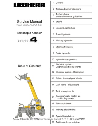
- 1. Í»®ª·½» Ó¿²«¿´ Ì¿¾´» ±º ݱ²¬»²¬ Ю±°»®¬§ ±º Ô·»¾¸»®®óÉ»®µ Ì»´º Ù³¾Ø Ô×ÛÞØÛÎÎ ïê ïë ïç îð ï î í ì ë ê é è ç ïð ïï ïî ïí ïì ïé ïè Ù»²»®¿´ ̱±´ ¿²¼ ©±®µ ·²¬®«½¬·±² Ì»½¸²·½¿´ ¼¿¬¿ ¿²¼ ³¿·²¬»²¿²½» ¹«·¼»´·²» Û²¹·²» ݱ«°´·²¹ô °´·¬¬»®¾±¨ Ì®¿ª»´ ¸§¼®¿«´·½ ɱ®µ·²¹ ¸§¼®¿«´·½ ͬ»»®·²¹ ¸§¼®¿«´·½ Þ®¿µ» ¸§¼®¿«´·½ ا¼®¿«´·½ ½±³°±²»²¬ Û´»½¬®·½¿´ §¬»³ ó Ü»½®·°¬·±² ߨ´» ñ ¬·®» ¿²¼ ¹»¿® ¸¿º¬ Ó¿·² º®¿³» ó ײ¬¿´´¿¬·±² Ñ°»®¿¬±®Ž ½¿¾ô ¸»¿¬»®ô ¿·® ½±²¼·¬·±²·²¹ §¬»³ Ì¿²µ ¿®®¿²¹»³»²¬ Ì»´»½±°·½ ¾±±³ Í°»½·¿´ ·²¬¿´´¿¬·±² ß¼¼·¬·±²¿´ ¼±½«³»²¬¿¬·±² ɱ®µ·²¹ ¿¬¬¿½¸³»²¬ ì Ì»´»½±°·½ ¸¿²¼´»® ÍÛÎ×ÛÍ Û´»½¬®·½¿´ §¬»³ ó Ü·¿¹®¿³ ¿²¼ ½±³°±²»²¬ Tuesday, 24.December 2019 13:18 printed this protected document! TL441-451_02-13_en.pdf ADMIN
- 2. Service Manual General Sub group index - General TL 441-10 F/N xxx-12000 Mjfcifss! 1.0.000 - 1 / 2 TL 451-10 F/N xxx-12000 TL 441-13 F/N xxx-12000 TL 451-13 F/N xxx-12000 1 General 1.0.000 Sub group index - General Foreword and explanations .............................................................................. 1.1 Safety guidelines ............................................................................................... 1.2 Charts ................................................................................................................. 1.3 Tightening torques..........................................................................................................1.3.001 Conversion charts...........................................................................................................1.3.002 Tapping holes .................................................................................................................1.3.003 Conservation guidelines................................................................................... 1.4 Material weights................................................................................................. 1.5 copyright by Tuesday, 24.December 2019 13:18 printed this protected document! TL441-451_02-13_en.pdf ADMIN
- 3. Service Manual General Foreword and explanations TL 441-10 F/N xxx-12000 MJFCIFSS! 1.1.000 - 1 / 2 TL 451-10 F/N xxx-12000 TL 441-13 F/N xxx-12000 TL 451-13 F/N xxx-12000 1.1.000 Foreword and explanations 1 For information This manual contains technical data, design and functional descriptions, work and adjustment instructions as well as numerous drawings, functional views and illustrations for the LIEBHERR – Telescopic loader. This manual should simplify competent customer service of our products. However, it does not replace expert and qualified user training and attendance of our factory training classes. Generally valid basic information is not listed. Refer to separate documentation for operational and spare parts information. The manual will be updated and expanded as necessary when changes occur in series. Note! This symbol is used in the manual for very important notes. For all tasks on the machine, accident prevention guidelines and safety guidelines must be strictly observed. Note! This manual is solely for the own use of the registered owner and may not be duplicated or copied, complete or in part, nor passed on to a third person and remains the property of LIEBHERR-Werk Telfs GmbH. All rights reserved - Printed in Austria. We reserve the right to make changes of technical details on the machine in comparison to the information and illustrations in this manual. Written and published by LIEBHERR-Werk Telfs GmbH., Technical Documentation Dept. 2 Explanation of layout To make it easier to find certain information and to simplify filing of updates, the following structure was developed: 6.3.130 - 1/2 Main group Sub group Type group Page No. Components (item) groups acc. to index Structure of main group according to sub group index Continuous running number and complete pages within the model group Structure based on telescopic boom type (13) and updates (0) copyright by Tuesday, 24.December 2019 13:18 printed this protected document! TL441-451_02-13_en.pdf ADMIN
- 4. https://www.aservicemanualpdf.com/ My Dear Friend! Thank you very much for visiting. Full manual if required, please enter the following URL into your browser. https://www.aservicemanualpdf.com/
- 5. General Service Manual Foreword and explanations 1.1.000 - 2 / 2 Mjfcifss! TL 441-10 F/N xxx-12000 TL 451-10 F/N xxx-12000 TL 441-13 F/N xxx-12000 TL 451-13 F/N xxx-12000 For the 3-digit type group number, the last number provides information regarding updates, whereby the two other numbers provide information about the type of machine, for example 000 and no additional machine serial number limitation means that the document is valid for all TL machine. for example 100/130 and no additional machine serial number limitation means that this document is valid for a TL 10 meter boom / TL 13 meter boom. for example 001/101/131 is a supplement which is valid from a certain machine serial number. Changes are issued with the same number, but with a later date. Updates have new numbers. If a page is valid only for a certain machine group, then this is noted in the header. 3 Itemization variations This symbol denotes a standard listing. This symbol means:“ The prerequisite must be met“. The maintenance personnel must first fulfill the described prerequisites, for example, to bring the machine in working position, to be able to carry out the steps described thereafter. This symbol denotes an activity step. The maintenance personnel is to become active on this point and carry out the described activity. This symbol denotes a result. The maintenance personal is alerted that there is a result after an activity step, for example after pressing the test button, the LED lights up. 4 General This note shows that a detail view of an illustration is shown rotated by a given angle, as compared to the actual installation position (in this case 180°). We hope that with the enclosed information we have taken yet another step to improve the service on the LIEBHERR telescopic handlers, crawler dozers, crawler loaders and pipe layers. LIEBHERR-Werk Telfs GmbH. Technical Documentation copyright by Tuesday, 24.December 2019 13:18 printed this protected document! TL441-451_02-13_en.pdf ADMIN
- 6. Service Manual General Safety guidelines TL 441-10 F/N xxx-12000 MJFCIFSS! 1.2.000 - 1 / 4 TL 451-10 F/N xxx-12000 TL 441-13 F/N xxx-12000 TL 451-13 F/N xxx-12000 1.2.000 Safety guidelines 1 Introduction Prior to and during the performance of tests, inspections and repairs, the following safety guidelines must be observed: Any type of work may only be carried out by qualified expert personnel or under their guidance and supervision. Qualified expert personnel are persons, who, based on their specialized training and experience, have sufficient knowledge in the area of telescopic handlers and the specific technology of our machines in particular and who are familiar with all applicable laws and general work protection regulations, accident prevention guidelines, regulations, guidelines and generally approved rules concerning technology so that they are able to evaluate if the earthmoving equipment is safe to operate and if the necessary work can be performed without endangering themselves or third persons. Always adhere to the adjustment values noted in the LIEBHERR documentation when performing adjustment work. At the delivery of a machine, the operating personnel must be trained using the current operating instructions. The safety guidelines noted in the instructions must be particularly observed. These safety guidelines must also be observed during inspection, adjustment or repair work. However, there are special repair and / or inspection work which require qualified personnel to follow another procedure than that noted in the safety guidelines. In such cases, qualified personnel or individuals performing the work under the supervision of such personnel should assure that additional safety precautions necessary to insure the safety of those involved in the repair and/ or third persons are taken. Such items of repair and/ or inspection work include, but are not limited to the following: - Opening the engine compartment doors while the engine running to carry out tests and / or adjustments. In these cases, it should be ensured that the cab door is properly secured during the entire duration of the work to prevent it from closing unexpectedly and / or inadvertently. Care should be exercised to assure that there will be no inadvertent or unintended contact of any part of the body with any moving and / or heated components. Wear only tightly fitted clothing (no scarves, no tie, no wide sleeves, etc.). copyright by Tuesday, 24.December 2019 13:18 printed this protected document! TL441-451_02-13_en.pdf ADMIN
- 7. General Service Manual Safety guidelines 1.2.000 - 2 / 4 Mjfcifss! TL 441-10 F/N xxx-12000 TL 451-10 F/N xxx-12000 TL 441-13 F/N xxx-12000 TL 451-13 F/N xxx-12000 Danger notes in this manual In the description of work, which can cause dangers for man or machine, the required safety measures are described in this manual. They are denoted with the following notes: Danger! Warns that certain working procedures without appropriate precautionary measures can result in fatal injuries. Warning! Warns that certain working procedures without appropriate precautionary measures can result in severe bodily injuries. Caution! Warns that certain working procedures without appropriate precautionary measures can result in bodily injuries or damage to the machine. Following these notes does not relieve you from observation of additional regulations and guidelines! The following must also be observed: - the safety regulations valid for the jobsite. - those issued by the legislature "Traffic regulations“. - the guidelines issued by trade associations. copyright by Tuesday, 24.December 2019 13:18 printed this protected document! TL441-451_02-13_en.pdf ADMIN
- 8. Service Manual General Safety guidelines TL 441-10 F/N xxx-12000 MJFCIFSS! 1.2.000 - 3 / 4 TL 451-10 F/N xxx-12000 TL 441-13 F/N xxx-12000 TL 451-13 F/N xxx-12000 Safety guidelines in these Operating instructions The detailed descriptions of the following safety guidelines are in the Operating instructions of the machine and must be strictly observed. 1 Introduction 2 Destined use 3 Signs on the machine 4 Safety guidelines 4.1 General safety guidelines 4.2 Crushing and burn prevention 4.3 Fire and explosion prevention 4.4 Machine start up safety 4.5 Engine start up safety 4.6 Machine operating safety 4.7 Machine parking safety 4.8 Machine transporting safety 4.9 Machine towing safety 4.10 Machine maintenance safety 4.11 Safety guidelines for welding work on the machine 4.12 Safety guidelines for working on the attachment 4.13 Safety guidelines when loading the machine with a crane 4.14 Safe maintenance of hydraulic hoses and hose lines 4.15 Safety guidelines for maintenance work on machines with hydro accumulators 4.16 Roll over protection (ROPS) and falling object protection (FOPS) 4.17 Attachment and components 4.18 Safe operation for material handling 4.19 Protection from vibration 4.20 Safety guidelines for operation with quick coupler adapter (optional) copyright by Tuesday, 24.December 2019 13:18 printed this protected document! TL441-451_02-13_en.pdf ADMIN
- 9. Service Manual General Tightening torques TL 441-10 F/N xxx-12000 MJFCIFSS! 1.3.001 - 1 / 4 TL 451-10 F/N xxx-12000 TL 441-13 F/N xxx-12000 TL 451-13 F/N xxx-12000 1.3.001 Tightening torques The preload values and tightening torques noted in the chart have been taken from the VDI guidelines 2230 of July 1986. Installation preload values FM and tightening torques MA for shoulder studs with standard metric or fine thread per DIN ISO 262 and DIN ISO 965 T2 (replacement for DIN 13 part 13) and wrench sizes for hex head screws with shaft DIN EN 24014 (replacement for DIN 931 part 1) or socket head screws DIN EN ISO 4762 (replacement for DIN 912) - The chart values are valid for screws with black or phosphated, zinc plated and DACROMET 500. Screws and nuts with black, phosphated or zinc plated, lightly lubricated. Medium friction value G = 0,12. Note! Any tightening torque values and/ or tightening procedures noted in drawings / parts lists, instructions or component descriptions must be adhered to and given preference over factory standards. Beginning with grade 10.9, the use of lock washers does no longer provide any safety action. he torque value according to the chart should be within the upper third of the existing range. When using impact wrenches, care must be taken so that the torque values are not exceeded. Check before and intermediately with a torque wrench. copyright by Tuesday, 24.December 2019 13:18 printed this protected document! TL441-451_02-13_en.pdf ADMIN
- 10. Service Manual Tools and work instructions Installation guidelines TL 441-10 F/N xxx-12000 MJFCIFSS! 2.3.000 - 1 / 4 TL 451-10 F/N xxx-12000 TL 441-13 F/N xxx-12000 TL 451-13 F/N xxx-12000 2.3.000 Installation guidelines 1 General Described in this section are installation notes for various components, which must be observed at reinstallation in case of a repair. 2 Installation notes 2.1 Equipment The threaded bores required to take on the 625 kg ballast weight are located outside the center of gravity of the weight. For that reason, the weight can get stuck at removal. To avoid this, the installation aids X (see section 2.1 Special tools) must be used. Because there is a risk of damage to the machine, the chains must be spread with the assistance of a suitable aid. Fig. 2-1 Removal – Ballast weight 625kg copyright by Tuesday, 24.December 2019 13:18 printed this protected document! TL441-451_02-13_en.pdf ADMIN
- 11. Tools and work instructions Service Manual Installation guidelines 2.3.000 - 2 / 4 Mjfcifss! TL 441-10 F/N xxx-12000 TL 451-10 F/N xxx-12000 TL 441-13 F/N xxx-12000 TL 451-13 F/N xxx-12000 2.2 Travel hydraulic 1.1.1 Variable displacement pump Since the installation notes refer to the positions in the sectional drawing, they are described in section 10.1 „Variable displacement pump – Travel hydraulic“. 1.1.2 Variable displacement motor Since the installation notes refer to the positions in the sectional drawing, they are described in section 10.2 „Variable displacement motor – Travel hydraulic“. 1.1.3 Gear pump The double gear pump is accessible via the cover on the inside of the main frame. Raise the telescope and secure it with the aid of the hoist support. Remove the cover plate At installation of the fixed displacement pump – double gear pump, the following must be observed: Clean and grease the sealing surfaces on motor and pump. Seal the sealing surfaces with liquid seal. Fig. 2-2 Double gear pump In addition, it must be observed that the distance between flange and gear is at least 0.5 mm. 2.2.1 Collector block When removing or replacing the pressure filter, pay attention to the flow direction (marked on the filters) at installation. When removing or replacing the check valve (cold start valve) 57, pay attention to the opening direction at installation. The correct flow direction is marked on the valve. copyright by Tuesday, 24.December 2019 13:18 printed this protected document! TL441-451_02-13_en.pdf ADMIN
- 12. Service Manual Tools and work instructions Installation guidelines TL 441-10 F/N xxx-12000 MJFCIFSS! 2.3.000 - 3 / 4 TL 451-10 F/N xxx-12000 TL 441-13 F/N xxx-12000 TL 451-13 F/N xxx-12000 Fig. 2-3 Installation of the pressure filter on the collector block 2.3 Working hydraulic 2.3.1 Telescope Since the installation notes refer to the positions in the sectional drawing, they are described in section 17.1 „Design and function“ or 17.2 „Repair instructions“. 2.3.2 Industrial control - Boom suspension Warning! Before starting any maintenance and repair work on the stabilizing module of the emergency down screw 252 (covered by a plug) back it out by 2-3 turns to relieve the pretension of the pressure accumulator 256 to the tank (connection T). Before putting it back into service, adhere the screw with Loctite. Fig. 2-4 Pressure accumulator The pretension of the pressure accumulator is reestablished when the telescope is raised. 2.4 Electrical system 2.4.1 DMS Sensor – rear axle See section 11.8 „DMS Sensor installation“. copyright by Tuesday, 24.December 2019 13:18 printed this protected document! TL441-451_02-13_en.pdf ADMIN
- 13. Tools and work instructions Service Manual Installation guidelines 2.3.000 - 4 / 4 Mjfcifss! TL 441-10 F/N xxx-12000 TL 451-10 F/N xxx-12000 TL 441-13 F/N xxx-12000 TL 451-13 F/N xxx-12000 2.5 Main frame 2.5.1 Variable motor mount Observe the correct arrangement of the components at installation. Tighten the hex head screws 5 with a tightening torque of 350 Nm. Fig. 2-5 Variable motor mount and installation of RPM sensor B2 Installation of RPM sensor Tighten the impulse sensor with 30Nm. Secure the sensor with Loctite to prevent it from twisting. With the aid of shims, adjust the distance between the RPM sensor B2 and the perforated plate 10. 2.5.2 Cab mount See section 16.1 „Operator’s cab“. 2.5.3 Stabilizers Secure the screws 24 at installation with Loctite. Fig 2-6 Installation of stabilizers for 13m telescopic loader copyright by Tuesday, 24.December 2019 13:18 printed this protected document! TL441-451_02-13_en.pdf ADMIN
- 14. Service Manual Technical data and Maintenance guidelines Maintenance and inspection guidelines TL 441-10 F/N xxx-12000 MJFCIFSS! 3.3.000 - 1 / 8 TL 451-10 F/N xxx-12000 TL 441-13 F/N xxx-12000 TL 451-13 F/N xxx-12000 3.3.000 Maintenance and inspection guidelines 1 General guidelines 1.1 Documentation of work to be carried out Note! For work to be performed, refer to the Maintenance and Inspection schedule for your particular Check off completed inspections or work by making a check mark on the copy of the form and have the completed form countersigned. The determined test values for the adjustment checks should be documented on the adjustment check list, corresponding to the machine model, see section 3.5. inspection booklet and send the appropriate Service ticket to the appropriate LIEBHERR company. After removing the old sticker, attach the new inspection sticker, which can also be found in the inspection booklet, clearly visible in the cab. Explain the set up and the contents of the machine documentation to the machine operator. Special emphasis should be given to safety regulations and maintenance task to be performed between inspections. 1.2 Safety guidelines During all maintenance, inspection or repair work, the applicable safety guidelines according to the section 1.2 and the Operating instructions for the machine must be observed. In addition, all applicable Federal, state and local work safety requirements, accident prevention regulations and local laws must be observed. 1.3 Intervals The given maintenance and inspection intervals may not be exceeded, if necessary they should be shortened. For example for: Changing the filter and sediments in case of very contaminated fuel; Cleaning the cooler if dirty; Changing the filter and oil at or after repairs, etc. Dispose of old oils, filters and other waste products properly! 1.4 General For all maintenance, inspection and repair work use only LIEBHERR Original spare parts and maintenance items. If the customer insists on the installati customer about a possible loss of warranty, and make a note to this effect on the inspection report. For general screw tightening torques, see section 1.3. copyright by Tuesday, 24.December 2019 13:18 printed this protected document! TL441-451_02-13_en.pdf ADMIN
- 15. Technical data and Maintenance guidelines Service Manual Maintenance and inspection guidelines 3.3.000 - 2 / 8 Mjfcifss! TL 441-10 F/N xxx-12000 TL 451-10 F/N xxx-12000 TL 441-13 F/N xxx-12000 TL 451-13 F/N xxx-12000 2 Performance guidelines 2.1 General inspection work 2.1.1 Check the entire machine for correct maintenance and proper condition If maintenance problems are found, discuss correct procedure with the maintenance personnel. If possible, also watch for possible operational errors and inform the machine operator accordingly, if necessary. If additional measures, maintenance or inspections for special equipment is required, then they should be completed and noted in writing. Determine any spare parts requirements or expected repairs, discuss and arrange them. 2.2 Inspection work on the Diesel engine 2.2.1 Check engine RPM The engine RPM can be checked with the evaluation software Lin-Diag. See also section 12.1 Application software LinDiag. The engine RPM can only be checked, not adjusted! 2.2.2 Replace the coolant with antifreeze The required ratio of antifreeze or corrosion inhibitor fluid is to be checked with an optical 1.1. The test procedure is independent of the coolant temperature. Fig. 2-1 Antifreeze protection display The display is made by a line between light and dark on the right scale of the sight gauge antifreeze protection is given (minus values above the 0°C mark, nominal value should be at least -37°C). For details, refer to the user instructions of the manufacturer. copyright by Tuesday, 24.December 2019 13:18 printed this protected document! TL441-451_02-13_en.pdf ADMIN
- 16. Service Manual Technical data and Maintenance guidelines Maintenance and inspection guidelines TL 441-10 F/N xxx-12000 MJFCIFSS! 3.3.000 - 3 / 8 TL 451-10 F/N xxx-12000 TL 441-13 F/N xxx-12000 TL 451-13 F/N xxx-12000 If only corrosion inhibitor oil (special fill) is used in exceptional cases, then this ratio can be read on the same scale. In this case, the display of each -1°C corresponds to the ratio of each 1 Vol.% of anticorrosion oil (Nominal value = 1%). Replace the coolant with antifreeze every 2 years. Drain the special fill coolant every year. To drain the coolant from the cooler and engine block, refer to the Operating instructions for the machine. Note! For service fluid specifications, refer to the Operating instructions. 2.2.3 Check / adjust the valve clearance Preparation for check Make sure that: the machine is in maintenance position. the battery master switch (optional) is turned off or that the negative cable is disconnected from the battery. the Diesel engine is cold. special tools are available (turning device new gaskets for the cylinder head cover are available, if needed. Procedure Remove the rocker lever cover and the crankcase vent pipe. Note! Inspect the contact surfaces of the valve tips, valve bridges and rocker lever wear parts visually. Check all parts for excessive wear, breaks and cracks. Replace any parts which show visible damage. Rocker levers, which show excessive valve clearance should generally be checked to determine damaged parts. Replace valves, seats, springs and retainers in pairs per cylinder, if they are damaged. In addition, replace the bridge if one of these parts is being replaced. Remove the plastic plugs or cover plate on the flywheel side from the adjustment turn opening (A) and the adjustment pin opening (B). Fig. 2-2 Flywheel housing adjustment openings rotation (in clockwise direction when viewed from the front) until cylinder No. 1 is on the top dead center (TDC) of the compression stroke. copyright by Tuesday, 24.December 2019 13:18 printed this protected document! TL441-451_02-13_en.pdf ADMIN
- 17. Technical data and Maintenance guidelines Service Manual Maintenance and inspection guidelines 3.3.000 - 4 / 8 Mjfcifss! TL 441-10 F/N xxx-12000 TL 451-10 F/N xxx-12000 TL 441-13 F/N xxx-12000 TL 451-13 F/N xxx-12000 Note! If the rocker levers of cylinder No. 1 can be moved, then the Diesel engine is at the TDC of No.1 in the compression stroke. If the rocker levers of cylinder No. 1 cannot be moved, then turn the Diesel engine by one full turn (360°) to the TDC No. 1 of the compression stroke. When the Diesel engine is set with the adjustment pin of the TDC of the compression stroke of cylinder No. 1, check the valve clearance according to the specifications. Specifications Test dimension Adjustment dimension Inlet valve clearance (rocker lever to valve bridge) [engine cold] - clearance Outlet valve clearance (rocker lever to valve bridge) [engine cold] - clearance torque 27 Nm Adjust the valve clearance Note! If the valves must be adjusted, release the counter nut (A) on the rocker lever adjustment screw. Hold the adjustment screw with a screw driver to prevent it from turning and tighten the counter nut according to the specification. After tightening the counter nut, check the clearance again. Readjust the clearance, if necessary. Fig. 2-3 Release the counter nut - rocker lever copyright by Tuesday, 24.December 2019 13:18 printed this protected document! TL441-451_02-13_en.pdf ADMIN
- 18. Service Manual Technical data and Maintenance guidelines Maintenance and inspection guidelines TL 441-10 F/N xxx-12000 MJFCIFSS! 3.3.000 - 5 / 8 TL 451-10 F/N xxx-12000 TL 441-13 F/N xxx-12000 TL 451-13 F/N xxx-12000 Fig. 2-4 Cylinder / valve arrangement A = Outlet valve E = Inlet valve Piston No. 1 on the top dead center (TDC) of the compression stroke: Fig. 2-5 Piston No. 1 on the top dead center Hold the piston No. 1 with the adjustment pin on the TDC of the compression stroke. Adjust the valve clearance on the outlet valves No. 1 and 3. Adjust the valve clearance on the inlet valves No. 1 and 2. Piston No. 4 on the top dead center (TDC) of the compression stroke: Fig. 2-6 Piston No. 4 on the top dead center Turn the crankshaft by 360°. Hold the piston No. 4 on the TDC of the compression stroke. Adjust the valve clearance on the outlet valves No. 2 and 4. Adjust the valve clearance on the inlet valves No. 3 and 4. Attach the rocker lever cover and the crankcase vent pipe. copyright by Tuesday, 24.December 2019 13:18 printed this protected document! TL441-451_02-13_en.pdf ADMIN
- 19. Thank you very much for your reading. Please Click Here. Then Get COMPLETE MANUAL. NO WAITING NOTE: If there is no response to click on the link above, please download the PDF document first and then click on it.
- 20. Technical data and Maintenance guidelines Service Manual Maintenance and inspection guidelines 3.3.000 - 6 / 8 Mjfcifss! TL 441-10 F/N xxx-12000 TL 451-10 F/N xxx-12000 TL 441-13 F/N xxx-12000 TL 451-13 F/N xxx-12000 2.2.4 Check the heater flange Fig. 2-7 Heater flange with electric connector cable Turn the battery master switch (Option) off or disconnect the negative cable from the battery. Disconnect the electric connector cable X on the heater flange. Connect an ohm meter or multi test unit to the terminals and check the resistance. If no resistance of 250 Ohm +/- 10% is obtained at 20°C, replace the heater flange. Connect the electrical connector cable on the heater flange. Turn on the battery master switch. 2.3 Inspection work on the hydraulic system 2.3.1 Check mountings and fittings for tight seating Check the mounting screws of hydraulic components (pumps, motors, tanks etc. ) as well as the flange connections for tight seating. Retighten, if necessary. Note! The required tightening torques are described in section 1.3.- Tightening torques. 2.3.2 Check / adjust all hydraulic pressures Carry out the pressure checks / adjustment accord 3.4 for the corresponding machine type and document the results. For details, data and instructions, refer to the adjustment check list or the corresponding sub group in the Service Manual. 2.4 Inspection work on the electrical system 2.4.1 Check / adjust the electronic load display The testing of the electronic load display is described in detail in the Operating instructions. If the specified values are not retained during the test, then the electronic load display must be adjusted. See section 11.7. 2.4.1 Check / adjust the control system of the travel drive and the working hydraulic On the telescopic handler, the check / adjustment is to be made with a Note Book and the software programs Lin-Diag Diagnostics software set for the travel drive or Bodem for the working hydraulic, according to the application description in section 12.1 and 12.2. Carry out the checks / adjustments according to the adjustment check list for the corresponding machine type, see section 3.4 - and document the results. copyright by Tuesday, 24.December 2019 13:18 printed this protected document! TL441-451_02-13_en.pdf ADMIN
- 21. Service Manual Technical data and Maintenance guidelines Maintenance and inspection guidelines TL 441-10 F/N xxx-12000 MJFCIFSS! 3.3.000 - 7 / 8 TL 451-10 F/N xxx-12000 TL 441-13 F/N xxx-12000 TL 451-13 F/N xxx-12000 Note! For special tools, see section 2.1.3. 2.4.2 Check the battery acid density (charge condition) Carry out the acid density test with an optical 2.1.1. Fig. 2-8 Battery charge condition The display made by a line between light and dark on the left scale of the indicator window. The indicator ranges are: GOOD =Battery charged FAIR =Battery half charged RECHARGE =Battery discharged Check the battery acid before adding water. Check each battery cell separately. If test values of all cells are below a density of 1,200, then the battery must be recharged with an external charger. If the values differ (difference 0,02) or if they are generally below 1,100, then the battery must be replaced. Note! Disconnect Connect For details about the use of a battery charge tester or to charge the battery, refer to the Danger! Mortal danger Battery acid has strongly acidic properties. Danger of explosion in case of spark formation! Handle carefully, wear safety glasses and gloves. Observe safety guidelines! copyright by Tuesday, 24.December 2019 13:18 printed this protected document! TL441-451_02-13_en.pdf ADMIN
- 22. Technical data and Maintenance guidelines Service Manual Maintenance and inspection guidelines 3.3.000 - 8 / 8 Mjfcifss! TL 441-10 F/N xxx-12000 TL 451-10 F/N xxx-12000 TL 441-13 F/N xxx-12000 TL 451-13 F/N xxx-12000 2.5 Inspection work on the air conditioning system 2.5.1 Inspection of air conditioning system For maintenance / problems on the air conditioning system, consult with an HVAC technician. For details, see section 16., or 2.6 Inspection work on the brake system 2.6.1 Check brake pad wear Fig.2-9 Preparation Fig.2-10 Check brake disks Preparation Back out the oil level plugs 1 from the axle casing 2 of the front axle. Check brake disks disks with the brake pedal pressed down with feeler gauge 3 (minimum 4.5 mm). If the gap is less, then the brake pads must be replaced. Note! For detailed description, see section 9. Brake hydraulic. 2.7 Inspection work on axles, tires 2.7.1 Check / adjust the play on the king pin bearings For the inspection procedure, refer to the Operating instructions. If a play is present on at least one king pin bearing, then it must be remedied. To do so, reduce the dimension of the installed shim by the measured deviation on the test gauge. For the exact adjustment procedure, refer to the repair instructions for the axles. A play of less than 0.1mm can be disregarded, because the smallest shim is 0.1 mm thick. For the shims, check the spare parts lists of the axles. Note! For the sectional drawing of the steering axle, see section 13.5. copyright by Tuesday, 24.December 2019 13:18 printed this protected document! TL441-451_02-13_en.pdf ADMIN
- 23. https://www.aservicemanualpdf.com/ My Dear Friend! Thank you very much for visiting. Full manual if required, please enter the following URL into your browser. https://www.aservicemanualpdf.com/