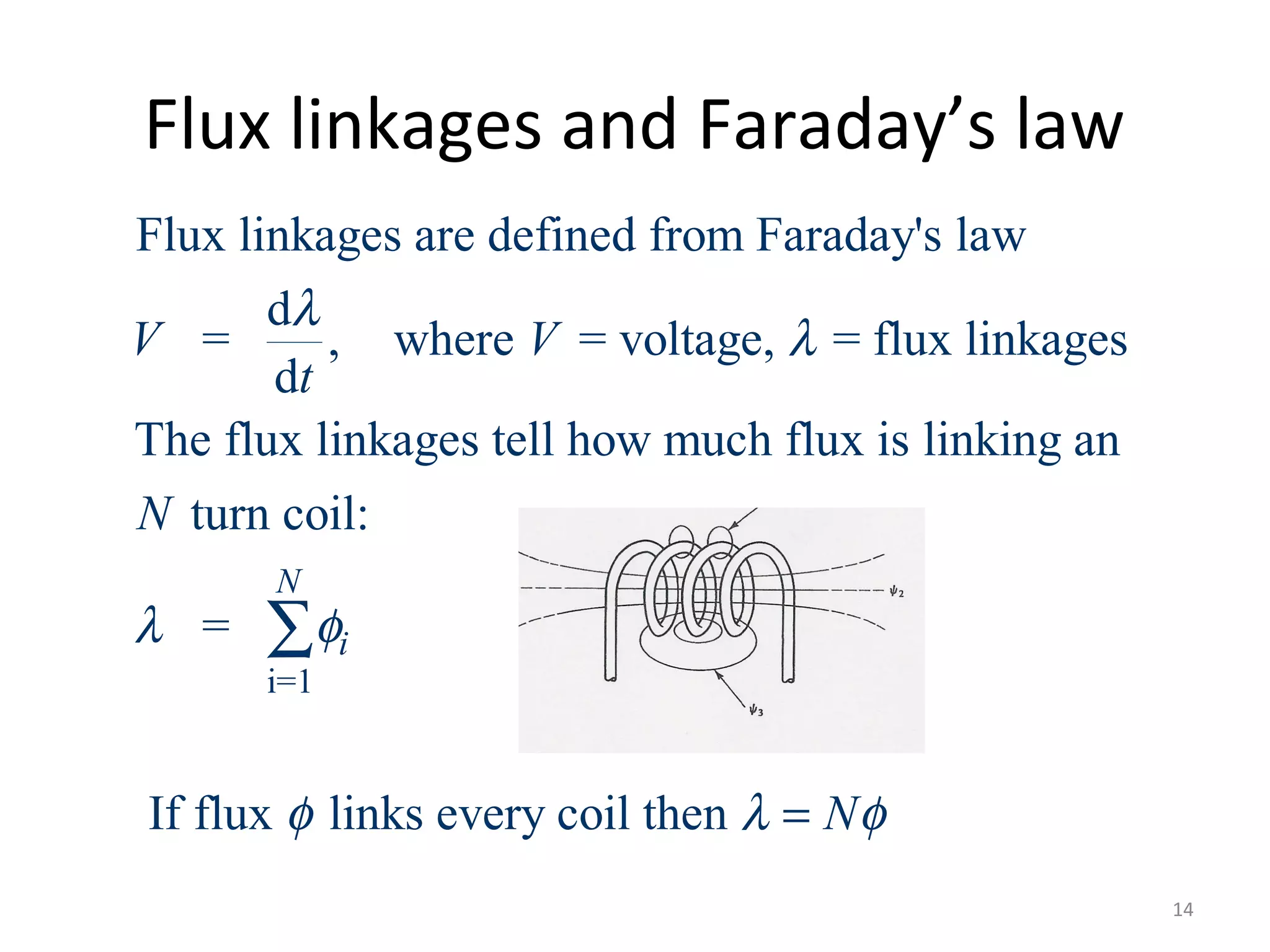
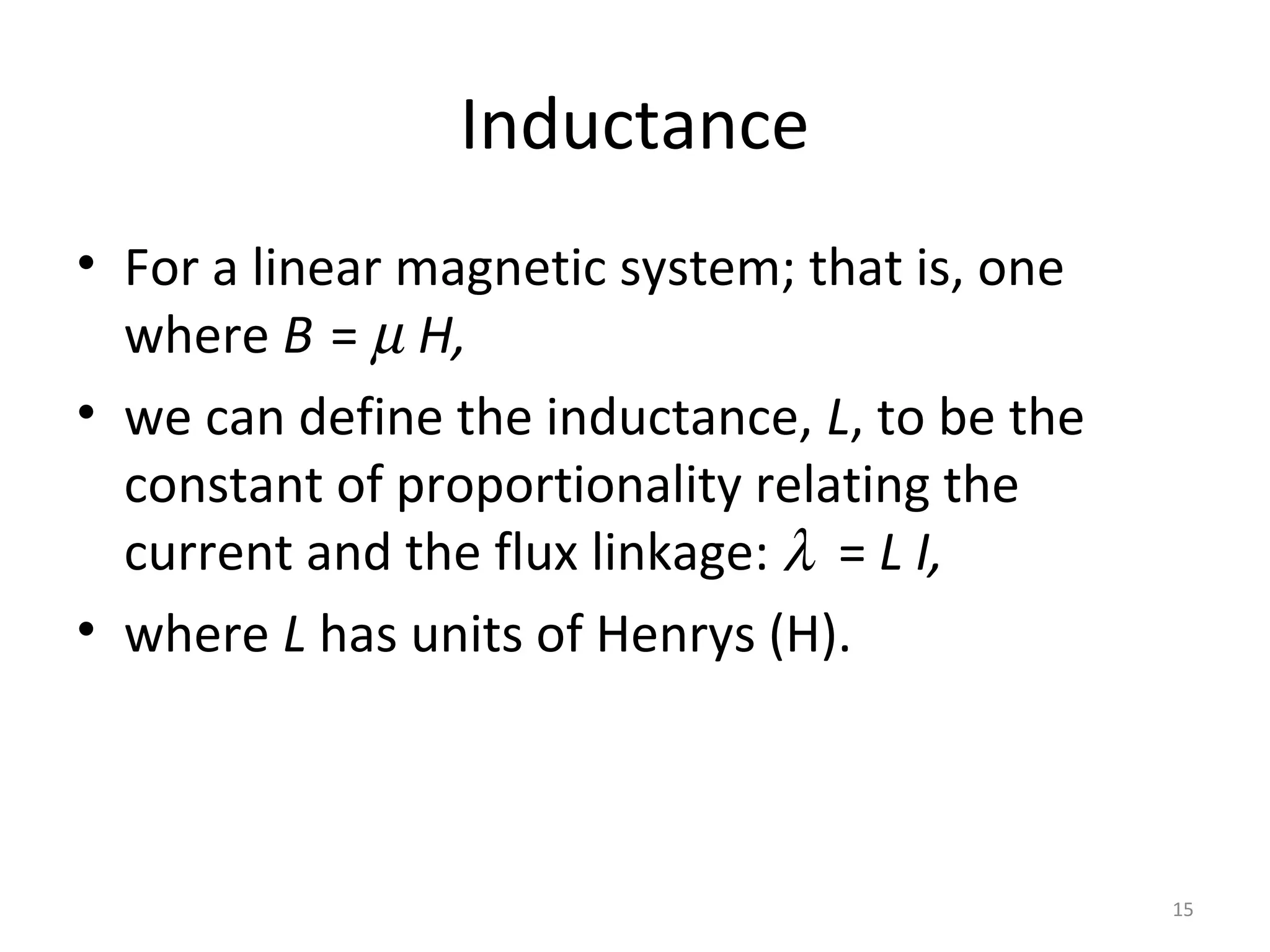
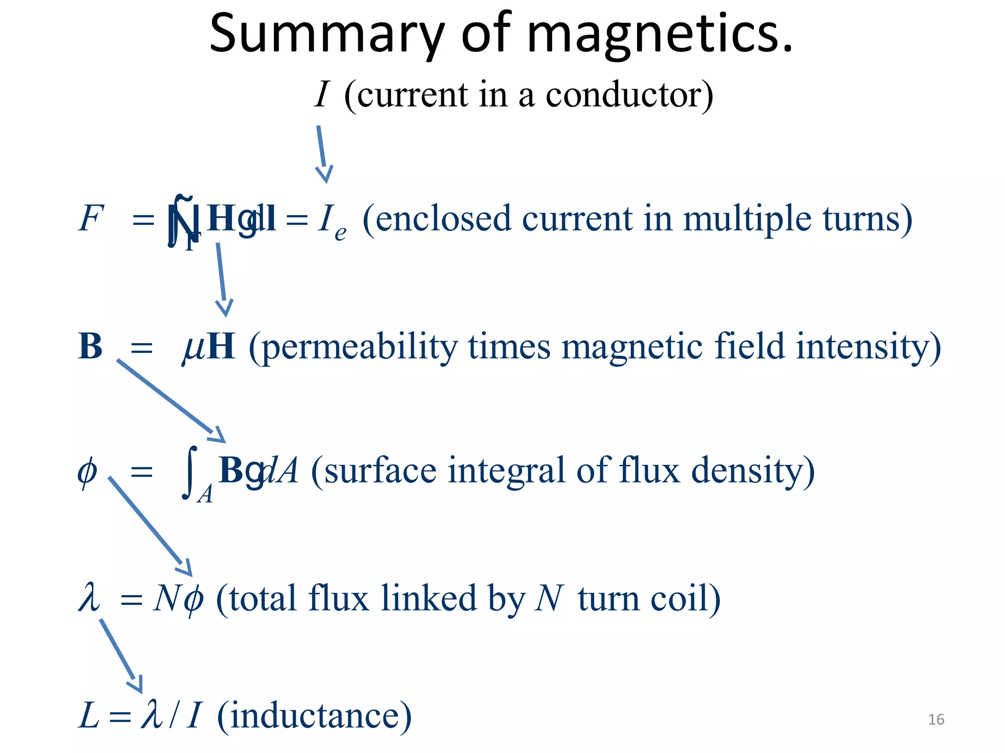
EE369
POWER SYSTEM ANALYSIS
Lecture 4
Power System Operation, Transmission Line
Modeling
Tom Overbye and Ross Baldick
1
Reading and Homework
• For lectures 4 through 6 read Chapter 4
– We will not be covering sections 4.7, 4.11, and 4.12 in
detail,
– We will return to chapter 3 later.
• HW 3 is Problems 2.43, 2.45, 2.46, 2.47, 2.49,
2.50, 2.51, 2.52, 4.2, 4.3, 4.5, 4.7 and Chapter 4
case study questions A through D; due Thursday
9/17.
• HW 4 is 2.31, 2.41, 2.48, 4.8, 4.10, 4.12, 4.13,
4.15, 4.19, 4.20, 4.22, due Thursday 9/24.
• Mid-term I is Thursday, October 1, covering up to
and including material in HW 4. 2
Development of Line Models
• Goals of this section are:
1) develop a simple model for transmission
lines, and
2) gain an intuitive feel for how the geometry of
the transmission line affects the model
parameters.
3
Primary Methods for Power Transfer
The most common methods for transfer of
electric power are:
1) Overhead ac
2) Underground ac
3) Overhead dc
4) Underground dc
The analysis will be developed for ac lines.
4
Magnetics Review
Magnetomotive force: symbol F, measured in
ampere-turns, which is the current enclosed by a
closed path,
Magnetic field intensity: symbol H, measured in
ampere-turns/meter:
– The existence of a current in a wire gives rise to an
associated magnetic field.
– The stronger the current, the more intense is the
magnetic field H.
Flux density: symbol B, measured in webers/m2
or teslas or gauss (1 Wb /m2
= 1T = 10,000G):
– Magnetic field intensity is associated with a magnetic
flux density.
5
Magnetics Review
Magnetic flux: symbol measured in webers,
which is the integral of flux density over a
surface.
Flux linkages measured in weber-turns.
– If the magnetic flux is varying (due to a changing
current) then a voltage will be induced in a
conductor that depends on how much magnetic flux
is enclosed (“linked”) by the loops of the conductor,
according to Faraday’s law.
Inductance: symbol L, measured in henrys:
– The ratio of flux linkages to the current in a coil.
,φ
,λ
6
Magnetics Review
• Ampere’s circuital law relates magnetomotive
force (the enclosed current in amps or amp-
turns) and magnetic field intensity (in amp-
turns/meter):
d
= mmf = magnetomotive force (amp-turns)
= magnetic field intensity (amp-turns/meter)
d = Vector differential path length (meters)
= Line integral about closed path
(d is tangent to path)
e
e
F I
F
I
Γ
Γ
= =
Γ
∫
∫
H l
H
l
l
gÑ
Ñ
= Algebraic sum of current linked by Γ 7
Line Integrals
•Line integrals are a generalization of “standard”
integration along, for example, the x-axis.
Integration along the
x-axis
Integration along a
general path, which
may be closed
Ampere’s law is most useful in cases of symmetry,
such as a circular path of radius x around an infinitely
long wire, so that H and dl are parallel, |H|= H is constant,
and |dl| integrates to equal the circumference 2πx.
8
Flux Density
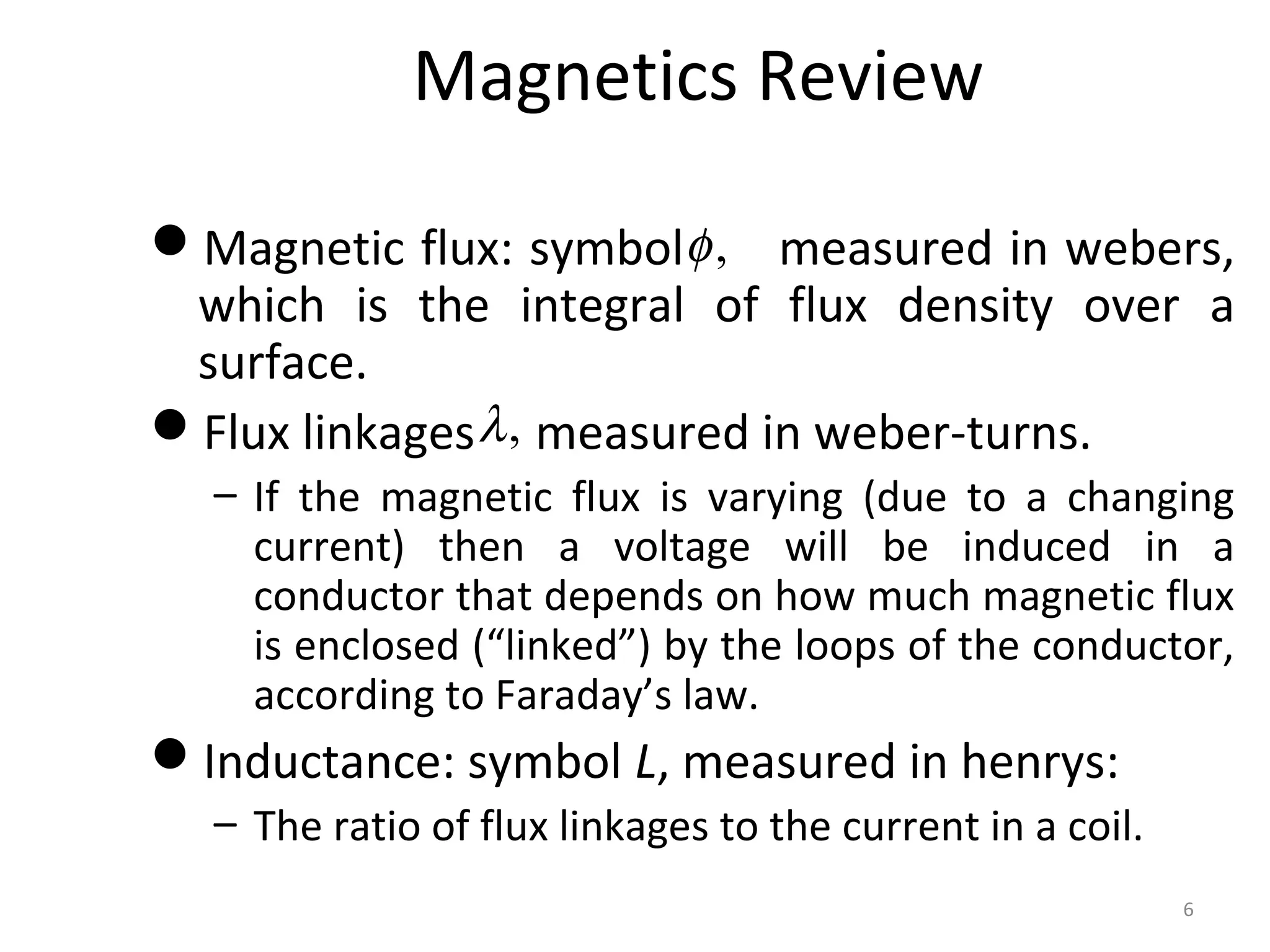
•Assuming no permanent magnetism, magnetic
field intensity and flux density are related by the
permeability of the medium.
0
0
= magnetic field intensity (amp-turns/meter)
= flux density (Tesla [T] or Gauss [G])
(1T = 10,000G)
For a linear magnetic material:
= where is the called the permeability
=
= permeability of frees
r
µ µ
µ µ µ
µ
H
B
B H
-7
pace = 4 10 H m
= relative permeability 1 for airr
π
µ
×
≈ 9
Magnetic Flux
2
Magnetic flux and flux density
magnetic flux (webers)
= flux density (webers/m or tesla)
Definition of flux passing through a surface is
=
= vector with direction normal to the surface
If flux
A
A
d
d
φ
φ
=
∫
B
B a
a
g
density B is uniform and perpendicular to an
area A then
= BAφ
10
Magnetic Fields from Single Wire
• Assume we have an infinitely long wire with
current of I =1000A.
• Consider a square, located between 4 and 5
meters from the wire and such that the
square and the wire are in the same plane.
• How much magnetic flux passes through the
square?
11
Magnetic Fields from Single Wire
• Magnetic flux passing through the square?
• Easiest way to solve the problem is to take
advantage of symmetry.
• As an integration path, we’ll choose a circle
with radius x, with x varying from 4 to 5
meters, with the wire at the center, so the
path encloses the current I. 12
Direction of H is given
by the “Right-hand” Rule
Single Line Example, cont’d
4
0 0
5 0
4
7
0
5
2
2
2 10 2
T Gauss
2
(1 meter)
2
5 5
ln 2 10 ln
2 4 4
4.46 10 Wb
A
I
d xH I H
x
I
B H
x x x
I
dA dx
x
I
I
π
π
µ µ
π
µ
φ
π
φ µ
π
φ
Γ
−
−
−
= = ⇒ =
×
= = = =
= = ×
= = ×
= ×
∫
∫ ∫
H l
B
g
g
Ñ
For reference,
the earth’s
magnetic field is
about 0.6 Gauss
(Central US)
13
H is perpendicular
to surface of square
Flux linkages and Faraday’s law
i=1
Flux linkages are defined from Faraday's law
d
= , where = voltage, = flux linkages
d
The flux linkages tell how much flux is linking an
turn coil:
=
If flux links every coil then
N
i
V V
t
N
N
λ
λ
λ φ
φ λ φ=
∑
14
Inductance
• For a linear magnetic system; that is, one
where B = µ H,
• we can define the inductance, L, to be the
constant of proportionality relating the
current and the flux linkage: λ = L I,
• where L has units of Henrys (H).
15
Summary of magnetics.
16
d (enclosed current in multiple turns)
(permeability times magnetic field intensity)
(surface integral of flux density)
(total flux li
(c
nked by tur
urrent in a conductor)
e
A
F I
dA
I
N N
µ
φ
λ φ
Γ
= =
=
=
=
∫
∫
H l
B H
B
g
g
Ñ
n coil)
/ (inductance)L Iλ=

Lecture 4

  • 1.
    EE369 POWER SYSTEM ANALYSIS Lecture4 Power System Operation, Transmission Line Modeling Tom Overbye and Ross Baldick 1
  • 2.
    Reading and Homework •For lectures 4 through 6 read Chapter 4 – We will not be covering sections 4.7, 4.11, and 4.12 in detail, – We will return to chapter 3 later. • HW 3 is Problems 2.43, 2.45, 2.46, 2.47, 2.49, 2.50, 2.51, 2.52, 4.2, 4.3, 4.5, 4.7 and Chapter 4 case study questions A through D; due Thursday 9/17. • HW 4 is 2.31, 2.41, 2.48, 4.8, 4.10, 4.12, 4.13, 4.15, 4.19, 4.20, 4.22, due Thursday 9/24. • Mid-term I is Thursday, October 1, covering up to and including material in HW 4. 2
  • 3.
    Development of LineModels • Goals of this section are: 1) develop a simple model for transmission lines, and 2) gain an intuitive feel for how the geometry of the transmission line affects the model parameters. 3
  • 4.
    Primary Methods forPower Transfer The most common methods for transfer of electric power are: 1) Overhead ac 2) Underground ac 3) Overhead dc 4) Underground dc The analysis will be developed for ac lines. 4
  • 5.
    Magnetics Review Magnetomotive force:symbol F, measured in ampere-turns, which is the current enclosed by a closed path, Magnetic field intensity: symbol H, measured in ampere-turns/meter: – The existence of a current in a wire gives rise to an associated magnetic field. – The stronger the current, the more intense is the magnetic field H. Flux density: symbol B, measured in webers/m2 or teslas or gauss (1 Wb /m2 = 1T = 10,000G): – Magnetic field intensity is associated with a magnetic flux density. 5
  • 6.
    Magnetics Review Magnetic flux:symbol measured in webers, which is the integral of flux density over a surface. Flux linkages measured in weber-turns. – If the magnetic flux is varying (due to a changing current) then a voltage will be induced in a conductor that depends on how much magnetic flux is enclosed (“linked”) by the loops of the conductor, according to Faraday’s law. Inductance: symbol L, measured in henrys: – The ratio of flux linkages to the current in a coil. ,φ ,λ 6
  • 7.
    Magnetics Review • Ampere’scircuital law relates magnetomotive force (the enclosed current in amps or amp- turns) and magnetic field intensity (in amp- turns/meter): d = mmf = magnetomotive force (amp-turns) = magnetic field intensity (amp-turns/meter) d = Vector differential path length (meters) = Line integral about closed path (d is tangent to path) e e F I F I Γ Γ = = Γ ∫ ∫ H l H l l gÑ Ñ = Algebraic sum of current linked by Γ 7
  • 8.
    Line Integrals •Line integralsare a generalization of “standard” integration along, for example, the x-axis. Integration along the x-axis Integration along a general path, which may be closed Ampere’s law is most useful in cases of symmetry, such as a circular path of radius x around an infinitely long wire, so that H and dl are parallel, |H|= H is constant, and |dl| integrates to equal the circumference 2πx. 8
  • 9.
    Flux Density •Assuming nopermanent magnetism, magnetic field intensity and flux density are related by the permeability of the medium. 0 0 = magnetic field intensity (amp-turns/meter) = flux density (Tesla [T] or Gauss [G]) (1T = 10,000G) For a linear magnetic material: = where is the called the permeability = = permeability of frees r µ µ µ µ µ µ H B B H -7 pace = 4 10 H m = relative permeability 1 for airr π µ × ≈ 9
  • 10.
    Magnetic Flux 2 Magnetic fluxand flux density magnetic flux (webers) = flux density (webers/m or tesla) Definition of flux passing through a surface is = = vector with direction normal to the surface If flux A A d d φ φ = ∫ B B a a g density B is uniform and perpendicular to an area A then = BAφ 10
  • 11.
    Magnetic Fields fromSingle Wire • Assume we have an infinitely long wire with current of I =1000A. • Consider a square, located between 4 and 5 meters from the wire and such that the square and the wire are in the same plane. • How much magnetic flux passes through the square? 11
  • 12.
    Magnetic Fields fromSingle Wire • Magnetic flux passing through the square? • Easiest way to solve the problem is to take advantage of symmetry. • As an integration path, we’ll choose a circle with radius x, with x varying from 4 to 5 meters, with the wire at the center, so the path encloses the current I. 12 Direction of H is given by the “Right-hand” Rule
  • 13.
    Single Line Example,cont’d 4 0 0 5 0 4 7 0 5 2 2 2 10 2 T Gauss 2 (1 meter) 2 5 5 ln 2 10 ln 2 4 4 4.46 10 Wb A I d xH I H x I B H x x x I dA dx x I I π π µ µ π µ φ π φ µ π φ Γ − − − = = ⇒ = × = = = = = = × = = × = × ∫ ∫ ∫ H l B g g Ñ For reference, the earth’s magnetic field is about 0.6 Gauss (Central US) 13 H is perpendicular to surface of square
  • 14.
    Flux linkages andFaraday’s law i=1 Flux linkages are defined from Faraday's law d = , where = voltage, = flux linkages d The flux linkages tell how much flux is linking an turn coil: = If flux links every coil then N i V V t N N λ λ λ φ φ λ φ= ∑ 14
  • 15.
    Inductance • For alinear magnetic system; that is, one where B = µ H, • we can define the inductance, L, to be the constant of proportionality relating the current and the flux linkage: λ = L I, • where L has units of Henrys (H). 15
  • 16.
    Summary of magnetics. 16 d(enclosed current in multiple turns) (permeability times magnetic field intensity) (surface integral of flux density) (total flux li (c nked by tur urrent in a conductor) e A F I dA I N N µ φ λ φ Γ = = = = = ∫ ∫ H l B H B g g Ñ n coil) / (inductance)L Iλ=