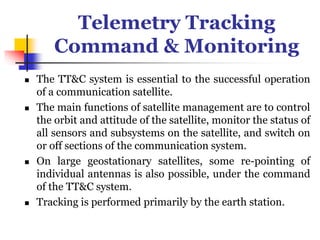
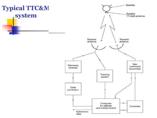
Satellite Subsystems
By
Ms. Madhuri N. Sachane
Telemetry Tracking
Command & Monitoring
 The TT&C system is essential to the successful operation
of a communication satellite.
 The main functions of satellite management are to control
the orbit and attitude of the satellite, monitor the status of
all sensors and subsystems on the satellite, and switch on
or off sections of the communication system.
 On large geostationary satellites, some re-pointing of
individual antennas is also possible, under the command
of the TT&C system.
 Tracking is performed primarily by the earth station.
Typical TTC&M
system
Telemetry & Monitoring
 The telemetry system at the satellite collects data from
many sensors within satellite and sends them to the
controlling earth station.
 As many as 100 or more sensors monitor pressure on fuel
tanks, voltage and current in the power conditioning
unit, critical voltage and current in communication
electronics.
 The temperature of subsystems, the sensor data, status of
subsystems, positions of switches, and sighting device for
altitude control.
Telemetry & Monitoring
 Telemetry data is usually transmitted as FSK or PSK of
low-power telemetry carrier using time division
techniques.
 Low data rate is normally used to allow the earth station
receiver to have a narrow bandwidth and thus maintain
high carrier-to-noise ratio (CNR).
 An entire TDM frame may contain thousands of bits of
data and take several seconds to transmit
 At the controlling earth station c0mputer can be used to
monitor, store and decode the telemetry data.
 so that status of any sensor or system at satellite can be
determined by the controller on the earth station.
Tracking
 The tracking system at the control earth station provides
information about the range, elevation, and azimuth for
a satellite.
 Data from velocity and acceleration sensors on the
satellite can be used to establish the change in the orbit
from the last known position by integrating data.
 Doppler shift observation at the control earth station
provides the rate of range change.
Tracking
 Active determination of range can be achieved by
transmitting pulses to the satellite from the control
earth station and measuring its round-trip delay.
 The position of a satellite can be measured by
triangulation from multiple earth stations.
 The position of a satellite can be determined within 10
m
 Ranging tones are used for range measurement, and
can be measured to millimeter accuracy.
Command
 A secure and effective command structure is vital to the
successful launch and operation of any communication
satellite.
 The command system makes changes the position and
attitude of the satellite, controls antenna positioning and
communication system configuration, and operates
switches at the satellite.
 During launch it is used to control the firing of the
apogee kick motor (AKM) and to spin up a spinner or
extend the solar sails of a three-axis stabilization
satellite.
Command
 The command structure must have safeguards against
inadvertent operation of a control due to error. The
control code is converted into a command word
which is sent in a TDM frame.
 After checking for validity in the satellite, the command
word is sent back to the control earth station via the
telemetry link where it is checked again.
 If it is received correctly, then an execute instruction
is sent to the satellite so that the command is
executed
Command
 The entire process may take 5 -10 seconds, but minimizes
the risk of erroneous commands causing a satellite
malfunction.
 The command and telemetry links are usually separated
from the communication system, although they may
operate in the same frequency band (for example, 6 and 4
GHz).
 Two levels of command system are used in the Intelsat
satellite:
 The main system operates in the 6-GHz band, in a gap
between the communication channel frequencies; the
main telemetry system uses a similar gap in the 4 -GHz
band.
The TTC&M antennas for the 6 / 4 GHz system on the
satellite.
Command
 These are earth-coverage horns, so the main system
can be used only after correct attitude of the satellite
is achieved.
 During the launch phase and injection into
geostationary orbit, the main TTC&M system may be
inoperable because the satellite does not have correct
attitude or has not extended its solar sails.
 Near Omni-directional antenna are used at either
UHF or S-band ( 2 -4GHz).
Command
 For the back up system, a great deal of redundancy and
sufficient margin in SNR at the satellite receiver are
allowed to guarantee control under the most adverse
conditions.
 The backup system provides control of the apogee kick
motor, the attitude control system and orbit control
thrusters, the solar sail deployment mechanism (if
fitted), and power conditioning unit.
 It is also used to eject the satellite from the
geostationary orbit and to switch off all transmitters at
the end of its useful life
Power Systems
 All communications satellites obtain their electric power
from solar cells which convert incident sunlight into
electrical energy.
 Some deep space planetary research spacecrafts have
used thermonuclear generators to supply electrical
power.
 But because of the danger to people on the earth in case
of launch fail and consequent nuclear spread,
communications satellites have not used nuclear
generators.
Power Systems
 Solar radiation falling on a satellite at geostationary orbit
has an intensity of 1.39 kW/m2 .
 The efficiency of solar cell is typically 20 to 25 % at the
beginning of life (BOL), but falls with time due to
aging of cells and etching of the surface by micrometer
impacts.
 Since sufficient power must be available at the end of
life (EOL) of the satellite to supply all the systems
on board, about 15 % extra area of solar cells is usually
provided as an allowance for aging.
 A spin-stabilized satellite has a cylindrical body covered
with solar cells.
Power Systems
 Because the cylindrical shape, half of the solar cells are not
illuminated at all,
 And at the edges of the illuminated half, the low angle of
incidence of sunlight results in little electric power being
generated.
 Recently a large communication satellite for direct
broadcasting generates up to 6 kW from solar power.
 A three-axis stabilized satellite can make better use of its
solar cell areas than a spinner, since solar sails can be
rotated to maintain normal incidence of the sunlight to the
cells.
Power Systems
 Only one-third of the total area of solar cells is needed
relative to a spinner, with some saving in weight.
 With large arrays, a three-axis stabilized satellite can have
more than 10 KW of power generated.
 In a three-axis stabilized satellite, solar sails must be
rotated by an electric motor once every 24 hours to keep
the cells in full sunlight.
 This causes the cells to heat up, typically to 50 to 80˚ C,
which causes a drop in output voltage.
 In a spinner design, the cells cool down when in shadow
and run at 20 to 30˚C , with somewhat higher efficiency
than a three-axis stabilized satellite
Power Systems
 The satellite must carry batteries provide power during
launch and eclipses.
 On geostationary orbit, eclipses occur during two periods
per year, around the spring and fall equinoxes, with
longest duration of about 70 min/day.
 To avoid the need for large, heavy batteries, a part of
communication system load may be shut down during
eclipse, but this technique is rarely used when telephony
or data traffic is carried.
 However, TV broadcasting satellites will not carry
sufficient battery capacity to supply their high-power
transmitters during eclipse, and must shut down during
eclipse.
Power Systems
 By locating the satellite 20˚ (which is equivalent to 1
hour and 20 minutes) west of the longitude of the
service area, the eclipse will occur after 1 a.m. local time
for the service area, when shut down is more acceptable.
 Batteries are usually of the sealed nickel hydrogen type
which do not gas when charging and have good
reliability and long life, and can safely discharge to 70 %
of their capacity.
 Typical battery voltages are 20 to 50 V with capacities of
20 to 100 ampere-hours
Communication
Subsystems
Description of Communication Subsystems
 A communication satellite exist to provide a platform in
a geostationary orbit for the relaying of voice, and video,
and data communications.
 All other subsystems on the satellite exit to support the
communication subsystem, although this may represent
a small part of volume, weight, and cost of the satellite.
 The growth in capacity is well shown in Figure for the
Intelsat system.
Communication
Subsystems
 Downlink is most critical part in the design of a satellite
communication system.
 The satellite transmitter has limited power.
 As link distance is about 36,000 km, the receiver power
level is very small and rarely exceeds 10(-10) W (that is, -
70 dB) even with a large aperture earth station antenna.
 For satisfactory performance, the signal power must
exceed the power of the noise generated in the receiver by
5 - 25 dB depending on the bandwidth of the transmitted
signal (which depends on the data rate) and modulation
scheme used.
Communication
Subsystems
 With low power transmitters, narrow receiver
bandwidths have to be used to maintain the required
SNRs.
 Higher power transmitters and satellites with directional
antennas enable wider bandwidths to be utilized,
increasing the capacity of the satellite.
 Early communication satellites had transponders of 250
or 500 MHz bandwidth but had low-gain antennas and
transmitters of 1 or 2 W output power.
 When the full bandwidth was used, the earth station
could not achieve an adequate SNR because the system
was power limited.
Communication
Subsystems
 Later generations of communication satellites also have
been power limited because they could not utilize the RF
bandwidth as efficiently as a terrestrial microwave
communication system.
 Their bandwidth utilization efficiency has been steadily
improved.
 In high-capacity satellites their available bandwidths
have been reused by employing several directional beams
at the same frequency (spatial frequency reuse) and
orthogonal polarizations at the same frequency
(polarization frequency reuse).
 Some satellites use multiple bands to obtain more
bandwidth.
Communication
Subsystems
 International agreements restrict the frequencies that
may be used for particular services and the regulations
are administered by the appropriate agency in each
country.
 The WARC (World Administrative radio Conference)
makes decisions on changes in frequency allocation.
 The standard spacing between GEO satellites was
originally 3o , but under regulations covering North
America and much of the rest of the world the spacing
has been reduced to 2o .
Communication
Subsystems
 The move to 2o spacing opened up extra slots for new
satellites in 6/ 4 and 14/11 GHz bands.
 Narrower spacing for satellite requires earth stations to
have narrower transmit beam antennas to avoid
interference with adjacent satellites.
 Higher frequencies make narrower antenna beams and
better control of coverage patterns possible.
 Satellite systems designed for Ku band (14/11 GHz) and
Ka band (30 / 20 GHz) have narrower antenna beams
and better control of coverage patterns than satellites
using C band (6/ 4 GHz).
Communication
Subsystems
 As the available orbital slots for GEO satellite have
filled up with satellites using 6/ 4 and 14/11 GHz
bands, attentions are focused on the use of the 30 /
20 GHz band.
 Originally this band had 3 -GHZ bandwidth allocated
to satellite services, but part of the band was
reallocated to the Land Multipoint Distribution
Service (LMDS).
 Approximately 2 GHZ of bandwidth is still available
for satellite systems at Ka band on an exclusive or
shared basis, which is equal to the combined
allocations of C and Ku bands.
Communication
Subsystems
 However, propagation in rain becomes a major factor
at frequencies above 10 GHz.
 Attenuation (in dB) in rain increases at roughly the
square of the frequency, so at 20 GHz rain
attenuation is four times larger in dB than 10 GHz.
Thank You

Lecture 10.ppt

  • 1.
  • 2.
    Telemetry Tracking Command &Monitoring  The TT&C system is essential to the successful operation of a communication satellite.  The main functions of satellite management are to control the orbit and attitude of the satellite, monitor the status of all sensors and subsystems on the satellite, and switch on or off sections of the communication system.  On large geostationary satellites, some re-pointing of individual antennas is also possible, under the command of the TT&C system.  Tracking is performed primarily by the earth station.
  • 3.
  • 4.
    Telemetry & Monitoring The telemetry system at the satellite collects data from many sensors within satellite and sends them to the controlling earth station.  As many as 100 or more sensors monitor pressure on fuel tanks, voltage and current in the power conditioning unit, critical voltage and current in communication electronics.  The temperature of subsystems, the sensor data, status of subsystems, positions of switches, and sighting device for altitude control.
  • 5.
    Telemetry & Monitoring Telemetry data is usually transmitted as FSK or PSK of low-power telemetry carrier using time division techniques.  Low data rate is normally used to allow the earth station receiver to have a narrow bandwidth and thus maintain high carrier-to-noise ratio (CNR).  An entire TDM frame may contain thousands of bits of data and take several seconds to transmit  At the controlling earth station c0mputer can be used to monitor, store and decode the telemetry data.  so that status of any sensor or system at satellite can be determined by the controller on the earth station.
  • 6.
    Tracking  The trackingsystem at the control earth station provides information about the range, elevation, and azimuth for a satellite.  Data from velocity and acceleration sensors on the satellite can be used to establish the change in the orbit from the last known position by integrating data.  Doppler shift observation at the control earth station provides the rate of range change.
  • 7.
    Tracking  Active determinationof range can be achieved by transmitting pulses to the satellite from the control earth station and measuring its round-trip delay.  The position of a satellite can be measured by triangulation from multiple earth stations.  The position of a satellite can be determined within 10 m  Ranging tones are used for range measurement, and can be measured to millimeter accuracy.
  • 8.
    Command  A secureand effective command structure is vital to the successful launch and operation of any communication satellite.  The command system makes changes the position and attitude of the satellite, controls antenna positioning and communication system configuration, and operates switches at the satellite.  During launch it is used to control the firing of the apogee kick motor (AKM) and to spin up a spinner or extend the solar sails of a three-axis stabilization satellite.
  • 9.
    Command  The commandstructure must have safeguards against inadvertent operation of a control due to error. The control code is converted into a command word which is sent in a TDM frame.  After checking for validity in the satellite, the command word is sent back to the control earth station via the telemetry link where it is checked again.  If it is received correctly, then an execute instruction is sent to the satellite so that the command is executed
  • 10.
    Command  The entireprocess may take 5 -10 seconds, but minimizes the risk of erroneous commands causing a satellite malfunction.  The command and telemetry links are usually separated from the communication system, although they may operate in the same frequency band (for example, 6 and 4 GHz).  Two levels of command system are used in the Intelsat satellite:  The main system operates in the 6-GHz band, in a gap between the communication channel frequencies; the main telemetry system uses a similar gap in the 4 -GHz band.
  • 11.
    The TTC&M antennasfor the 6 / 4 GHz system on the satellite.
  • 12.
    Command  These areearth-coverage horns, so the main system can be used only after correct attitude of the satellite is achieved.  During the launch phase and injection into geostationary orbit, the main TTC&M system may be inoperable because the satellite does not have correct attitude or has not extended its solar sails.  Near Omni-directional antenna are used at either UHF or S-band ( 2 -4GHz).
  • 13.
    Command  For theback up system, a great deal of redundancy and sufficient margin in SNR at the satellite receiver are allowed to guarantee control under the most adverse conditions.  The backup system provides control of the apogee kick motor, the attitude control system and orbit control thrusters, the solar sail deployment mechanism (if fitted), and power conditioning unit.  It is also used to eject the satellite from the geostationary orbit and to switch off all transmitters at the end of its useful life
  • 14.
    Power Systems  Allcommunications satellites obtain their electric power from solar cells which convert incident sunlight into electrical energy.  Some deep space planetary research spacecrafts have used thermonuclear generators to supply electrical power.  But because of the danger to people on the earth in case of launch fail and consequent nuclear spread, communications satellites have not used nuclear generators.
  • 15.
    Power Systems  Solarradiation falling on a satellite at geostationary orbit has an intensity of 1.39 kW/m2 .  The efficiency of solar cell is typically 20 to 25 % at the beginning of life (BOL), but falls with time due to aging of cells and etching of the surface by micrometer impacts.  Since sufficient power must be available at the end of life (EOL) of the satellite to supply all the systems on board, about 15 % extra area of solar cells is usually provided as an allowance for aging.  A spin-stabilized satellite has a cylindrical body covered with solar cells.
  • 16.
    Power Systems  Becausethe cylindrical shape, half of the solar cells are not illuminated at all,  And at the edges of the illuminated half, the low angle of incidence of sunlight results in little electric power being generated.  Recently a large communication satellite for direct broadcasting generates up to 6 kW from solar power.  A three-axis stabilized satellite can make better use of its solar cell areas than a spinner, since solar sails can be rotated to maintain normal incidence of the sunlight to the cells.
  • 17.
    Power Systems  Onlyone-third of the total area of solar cells is needed relative to a spinner, with some saving in weight.  With large arrays, a three-axis stabilized satellite can have more than 10 KW of power generated.  In a three-axis stabilized satellite, solar sails must be rotated by an electric motor once every 24 hours to keep the cells in full sunlight.  This causes the cells to heat up, typically to 50 to 80˚ C, which causes a drop in output voltage.  In a spinner design, the cells cool down when in shadow and run at 20 to 30˚C , with somewhat higher efficiency than a three-axis stabilized satellite
  • 18.
    Power Systems  Thesatellite must carry batteries provide power during launch and eclipses.  On geostationary orbit, eclipses occur during two periods per year, around the spring and fall equinoxes, with longest duration of about 70 min/day.  To avoid the need for large, heavy batteries, a part of communication system load may be shut down during eclipse, but this technique is rarely used when telephony or data traffic is carried.  However, TV broadcasting satellites will not carry sufficient battery capacity to supply their high-power transmitters during eclipse, and must shut down during eclipse.
  • 19.
    Power Systems  Bylocating the satellite 20˚ (which is equivalent to 1 hour and 20 minutes) west of the longitude of the service area, the eclipse will occur after 1 a.m. local time for the service area, when shut down is more acceptable.  Batteries are usually of the sealed nickel hydrogen type which do not gas when charging and have good reliability and long life, and can safely discharge to 70 % of their capacity.  Typical battery voltages are 20 to 50 V with capacities of 20 to 100 ampere-hours
  • 20.
    Communication Subsystems Description of CommunicationSubsystems  A communication satellite exist to provide a platform in a geostationary orbit for the relaying of voice, and video, and data communications.  All other subsystems on the satellite exit to support the communication subsystem, although this may represent a small part of volume, weight, and cost of the satellite.  The growth in capacity is well shown in Figure for the Intelsat system.
  • 21.
    Communication Subsystems  Downlink ismost critical part in the design of a satellite communication system.  The satellite transmitter has limited power.  As link distance is about 36,000 km, the receiver power level is very small and rarely exceeds 10(-10) W (that is, - 70 dB) even with a large aperture earth station antenna.  For satisfactory performance, the signal power must exceed the power of the noise generated in the receiver by 5 - 25 dB depending on the bandwidth of the transmitted signal (which depends on the data rate) and modulation scheme used.
  • 22.
    Communication Subsystems  With lowpower transmitters, narrow receiver bandwidths have to be used to maintain the required SNRs.  Higher power transmitters and satellites with directional antennas enable wider bandwidths to be utilized, increasing the capacity of the satellite.  Early communication satellites had transponders of 250 or 500 MHz bandwidth but had low-gain antennas and transmitters of 1 or 2 W output power.  When the full bandwidth was used, the earth station could not achieve an adequate SNR because the system was power limited.
  • 23.
    Communication Subsystems  Later generationsof communication satellites also have been power limited because they could not utilize the RF bandwidth as efficiently as a terrestrial microwave communication system.  Their bandwidth utilization efficiency has been steadily improved.  In high-capacity satellites their available bandwidths have been reused by employing several directional beams at the same frequency (spatial frequency reuse) and orthogonal polarizations at the same frequency (polarization frequency reuse).  Some satellites use multiple bands to obtain more bandwidth.
  • 24.
    Communication Subsystems  International agreementsrestrict the frequencies that may be used for particular services and the regulations are administered by the appropriate agency in each country.  The WARC (World Administrative radio Conference) makes decisions on changes in frequency allocation.  The standard spacing between GEO satellites was originally 3o , but under regulations covering North America and much of the rest of the world the spacing has been reduced to 2o .
  • 25.
    Communication Subsystems  The moveto 2o spacing opened up extra slots for new satellites in 6/ 4 and 14/11 GHz bands.  Narrower spacing for satellite requires earth stations to have narrower transmit beam antennas to avoid interference with adjacent satellites.  Higher frequencies make narrower antenna beams and better control of coverage patterns possible.  Satellite systems designed for Ku band (14/11 GHz) and Ka band (30 / 20 GHz) have narrower antenna beams and better control of coverage patterns than satellites using C band (6/ 4 GHz).
  • 26.
    Communication Subsystems  As theavailable orbital slots for GEO satellite have filled up with satellites using 6/ 4 and 14/11 GHz bands, attentions are focused on the use of the 30 / 20 GHz band.  Originally this band had 3 -GHZ bandwidth allocated to satellite services, but part of the band was reallocated to the Land Multipoint Distribution Service (LMDS).  Approximately 2 GHZ of bandwidth is still available for satellite systems at Ka band on an exclusive or shared basis, which is equal to the combined allocations of C and Ku bands.
  • 27.
    Communication Subsystems  However, propagationin rain becomes a major factor at frequencies above 10 GHz.  Attenuation (in dB) in rain increases at roughly the square of the frequency, so at 20 GHz rain attenuation is four times larger in dB than 10 GHz.
  • 28.