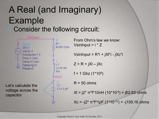
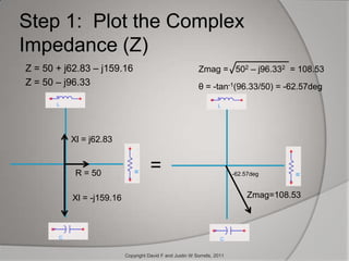
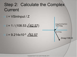
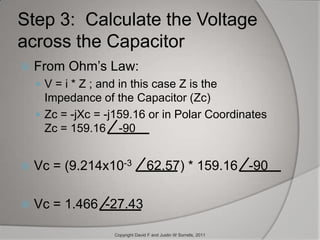
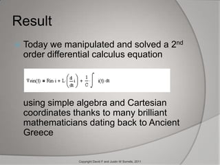
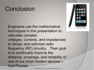
From Ancient Greece to cell phonesMathematics Used Everyday in Modern ElectronicsbyDavid and Justin Sorrells
Euclidean SpaceEuclid of Alexander, Greece, 300BCESymbol EnEvery point in 3 dimensional Euclidean Space (E3)can be located or mapped to a unique x, y, and z coordinate valueThe x, y, and z axes in Euclidean space are Orthogonal (Perpendicular)Copyright David F and Justin W Sorrells, 2011
Cartesian CoordinatesRenè Descartes, France, 1600 CE2 Dimensional Euclidean Space E2 AKA a PlaneThe Cartesian x and y axes are OrthogonalEvery point in a 2 dimensional Cartesian Coordinate Plane can be mapped to a unique x and y coordinate valueY axis(1,3)3X axis1Copyright David F and Justin W Sorrells, 2011
The Unit CircleGupta Period, India, 550 CEPythagoras, Greece, 490 CEUnit Circle    Radius = 1Symbol S1x2 + y2 = h2 = r2 = 1Unique x and y coordinates can be expressed as Polar coordinates (r,θ)Y axis(0,1)ry(-1,0)θX axisx(1,0)(-1,-1)Copyright David F and Justin W Sorrells, 2011
Cartesian/Polar Coordinates to Trigonometric  IdentitiesHipparchus, Greece, 2 CEUnit Circle    Radius = 1sin(θ)Identities:x = r * cos(θ)y = r * sin(θ)Since x2 + y2 = r2--and--  r = 1--then– sin2(θ)+cos2(θ) = 1ryθcos(θ)xCopyright David F and Justin W Sorrells, 2011
Complex PlaneHeron of Alexandria, Greece, 10-70 CERafael Bombelli, Italy, 1572 CECartesian Coordinates can be expressed as a real axis and an imaginary axis instead of x axis and y axisNamed the Complex Plane because of the complex number (1+i3) notation.i = j =   -1   ; (1+i3) = (1+j3)In electronics, i is the variable for current so j was chosen to represent complex notation.Imaginary axis(1,i3) or 1+i3i3Real axis1Copyright David F and Justin W Sorrells, 2011
Complex Polar Plane with Unit CircleJean-Robert Argand, France, 1806 CEThe notation cos(θ) + jsin(θ) defines the position of V which is known as a VectorSimply by knowing the angle θ on the complex plane, we can describe any Vector by calculating cos(θ) for the x-coordinate and jsin(θ) for the y-coordinatejsin(θ)Unit Circle    Radius = 1Vjsin(θ)θcos(θ)cos(θ)Copyright David F and Justin W Sorrells, 2011
Euler Makes another LeapLeonhard Euler, Switzerland, 1783 ejθ = cos(θ) + jsin(θ)With Euler’s formula, we can express any Vector in the complex plane simply by writing ejθ.jsin(θ)Unit Circle    Radius = 1Vjsin(θ)θcos(θ)cos(θ)Copyright David F and Justin W Sorrells, 2011
Laplace Ties it all TogetherPierre-Simon Laplace, France, 1800 Laplace TransformLaplace uses Euler’s ejθ relationship and extends it to e-st with s defined as j*2*π*f, which can be expanded to: e-st = -(cos(2*π*f*t) + jsin(i*2*π*f*t))Now we can define the response of f(t) in terms of frequency instead of θ (angle)Who uses this information?Copyright David F and Justin W Sorrells, 2011
Electrical EngineersElectrical Engineers use mathematics that date back 205 to 2300 years to mathematically describe all basic passive electronic components circuit responses using simple algebra in the frequency domain.Time domain Equations	Components        Laplace Transform ImpedanceLaplace, and all those before him makes it so that we don’t have to solve differential time domain equations to calculate how resistors, capacitors, and inductors behave at any given frequency.Copyright David F and Justin W Sorrells, 2011
Easy as PiImaginaryAxisThe inductive impedance is plotted on the +j or positive imaginary axisThe capacitive impedance is plotted on the –j or negative imaginary axisThe resistance is plotted on 	the real axisf = frequencyL = inductanceC = capacitanceR = resistancej2πfLRReal Axis   -j2πfCCopyright David F and Justin W Sorrells, 2011
Ohm’s Law (one more simple equation)Georg Ohm, Germany, 1827 CEOhm’s Law for Direct Current (DC):
Voltage = Current * Resistance
V = i * R
Ohm’s Law for Alternating Current (AC):
Voltage = Current * Impedance
V = i * Z
Impedance is a complex parameter defined as Re+jXCopyright David F and Justin W Sorrells, 2011
A Real (and Imaginary) ExampleConsider the following circuit:From Ohm’s law we know:VsinInput = i * ZVsinInput = R*i + jXl*i - jXc*iZ = R + jXl – jXcf = 1 Ghz (1*109)R = 50 ohmsXl = j2* π*f*10nH (10*10-9) = j62.83 ohms Xc = -j2* π*f*1pF (1*10-12) = -j159.16 ohmsLet’s calculate the voltage across the capacitorCopyright David F and Justin W Sorrells, 2011
Step 1:  Plot the Complex Impedance (Z)Z = 50 + j62.83 – j159.16Z = 50 – j96.33Zmag =   502 – j96.332   = 108.53θ = -tan-1(96.33/50) = -62.57deg Xl = j62.83 =R = 50 -62.57deg Zmag=108.53 Xl = -j159.16 Copyright David F and Justin W Sorrells, 2011

Justin Math Presentation Rev1.2

  • 1.
    From Ancient Greeceto cell phonesMathematics Used Everyday in Modern ElectronicsbyDavid and Justin Sorrells
  • 2.
    Euclidean SpaceEuclid ofAlexander, Greece, 300BCESymbol EnEvery point in 3 dimensional Euclidean Space (E3)can be located or mapped to a unique x, y, and z coordinate valueThe x, y, and z axes in Euclidean space are Orthogonal (Perpendicular)Copyright David F and Justin W Sorrells, 2011
  • 3.
    Cartesian CoordinatesRenè Descartes,France, 1600 CE2 Dimensional Euclidean Space E2 AKA a PlaneThe Cartesian x and y axes are OrthogonalEvery point in a 2 dimensional Cartesian Coordinate Plane can be mapped to a unique x and y coordinate valueY axis(1,3)3X axis1Copyright David F and Justin W Sorrells, 2011
  • 4.
    The Unit CircleGuptaPeriod, India, 550 CEPythagoras, Greece, 490 CEUnit Circle Radius = 1Symbol S1x2 + y2 = h2 = r2 = 1Unique x and y coordinates can be expressed as Polar coordinates (r,θ)Y axis(0,1)ry(-1,0)θX axisx(1,0)(-1,-1)Copyright David F and Justin W Sorrells, 2011
  • 5.
    Cartesian/Polar Coordinates toTrigonometric IdentitiesHipparchus, Greece, 2 CEUnit Circle Radius = 1sin(θ)Identities:x = r * cos(θ)y = r * sin(θ)Since x2 + y2 = r2--and-- r = 1--then– sin2(θ)+cos2(θ) = 1ryθcos(θ)xCopyright David F and Justin W Sorrells, 2011
  • 6.
    Complex PlaneHeron ofAlexandria, Greece, 10-70 CERafael Bombelli, Italy, 1572 CECartesian Coordinates can be expressed as a real axis and an imaginary axis instead of x axis and y axisNamed the Complex Plane because of the complex number (1+i3) notation.i = j = -1 ; (1+i3) = (1+j3)In electronics, i is the variable for current so j was chosen to represent complex notation.Imaginary axis(1,i3) or 1+i3i3Real axis1Copyright David F and Justin W Sorrells, 2011
  • 7.
    Complex Polar Planewith Unit CircleJean-Robert Argand, France, 1806 CEThe notation cos(θ) + jsin(θ) defines the position of V which is known as a VectorSimply by knowing the angle θ on the complex plane, we can describe any Vector by calculating cos(θ) for the x-coordinate and jsin(θ) for the y-coordinatejsin(θ)Unit Circle Radius = 1Vjsin(θ)θcos(θ)cos(θ)Copyright David F and Justin W Sorrells, 2011
  • 8.
    Euler Makes anotherLeapLeonhard Euler, Switzerland, 1783 ejθ = cos(θ) + jsin(θ)With Euler’s formula, we can express any Vector in the complex plane simply by writing ejθ.jsin(θ)Unit Circle Radius = 1Vjsin(θ)θcos(θ)cos(θ)Copyright David F and Justin W Sorrells, 2011
  • 9.
    Laplace Ties itall TogetherPierre-Simon Laplace, France, 1800 Laplace TransformLaplace uses Euler’s ejθ relationship and extends it to e-st with s defined as j*2*π*f, which can be expanded to: e-st = -(cos(2*π*f*t) + jsin(i*2*π*f*t))Now we can define the response of f(t) in terms of frequency instead of θ (angle)Who uses this information?Copyright David F and Justin W Sorrells, 2011
  • 10.
    Electrical EngineersElectrical Engineersuse mathematics that date back 205 to 2300 years to mathematically describe all basic passive electronic components circuit responses using simple algebra in the frequency domain.Time domain Equations Components Laplace Transform ImpedanceLaplace, and all those before him makes it so that we don’t have to solve differential time domain equations to calculate how resistors, capacitors, and inductors behave at any given frequency.Copyright David F and Justin W Sorrells, 2011
  • 11.
    Easy as PiImaginaryAxisTheinductive impedance is plotted on the +j or positive imaginary axisThe capacitive impedance is plotted on the –j or negative imaginary axisThe resistance is plotted on the real axisf = frequencyL = inductanceC = capacitanceR = resistancej2πfLRReal Axis -j2πfCCopyright David F and Justin W Sorrells, 2011
  • 12.
    Ohm’s Law (onemore simple equation)Georg Ohm, Germany, 1827 CEOhm’s Law for Direct Current (DC):
  • 13.
    Voltage = Current* Resistance
  • 14.
  • 15.
    Ohm’s Law forAlternating Current (AC):
  • 16.
  • 17.
  • 18.
    Impedance is acomplex parameter defined as Re+jXCopyright David F and Justin W Sorrells, 2011
  • 19.
    A Real (andImaginary) ExampleConsider the following circuit:From Ohm’s law we know:VsinInput = i * ZVsinInput = R*i + jXl*i - jXc*iZ = R + jXl – jXcf = 1 Ghz (1*109)R = 50 ohmsXl = j2* π*f*10nH (10*10-9) = j62.83 ohms Xc = -j2* π*f*1pF (1*10-12) = -j159.16 ohmsLet’s calculate the voltage across the capacitorCopyright David F and Justin W Sorrells, 2011
  • 20.
    Step 1: Plot the Complex Impedance (Z)Z = 50 + j62.83 – j159.16Z = 50 – j96.33Zmag = 502 – j96.332 = 108.53θ = -tan-1(96.33/50) = -62.57deg Xl = j62.83 =R = 50 -62.57deg Zmag=108.53 Xl = -j159.16 Copyright David F and Justin W Sorrells, 2011