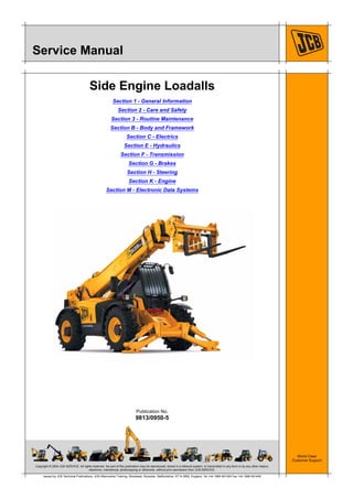
This document provides an overview and applications tables for a service manual covering JCB Loadall side engine machines. It lists the machine models covered, sections of the manual, and which topics apply to each machine variant. Copyright information is provided and reproduction of the publication is restricted without permission. It is issued by JCB Technical Publications and includes general information, care and safety, maintenance, body and framework systems, electrics, hydraulics, transmission, brakes, steering, engine and electronic systems.
Things to remember while upgrading the brakes of your carjennifermiller8137
Upgrading the brakes of your car? Keep these things in mind before doing so. Additionally, start using an OBD 2 GPS tracker so that you never miss a vehicle maintenance appointment. On top of this, a car GPS tracker will also let you master good driving habits that will let you increase the operational life of your car’s brakes.
Core technology of Hyundai Motor Group's EV platform 'E-GMP'Hyundai Motor Group
What’s the force behind Hyundai Motor Group's EV performance and quality?
Maximized driving performance and quick charging time through high-density battery pack and fast charging technology and applicable to various vehicle types!
Discover more about Hyundai Motor Group’s EV platform ‘E-GMP’!
𝘼𝙣𝙩𝙞𝙦𝙪𝙚 𝙋𝙡𝙖𝙨𝙩𝙞𝙘 𝙏𝙧𝙖𝙙𝙚𝙧𝙨 𝙞𝙨 𝙫𝙚𝙧𝙮 𝙛𝙖𝙢𝙤𝙪𝙨 𝙛𝙤𝙧 𝙢𝙖𝙣𝙪𝙛𝙖𝙘𝙩𝙪𝙧𝙞𝙣𝙜 𝙩𝙝𝙚𝙞𝙧 𝙥𝙧𝙤𝙙𝙪𝙘𝙩𝙨. 𝙒𝙚 𝙝𝙖𝙫𝙚 𝙖𝙡𝙡 𝙩𝙝𝙚 𝙥𝙡𝙖𝙨𝙩𝙞𝙘 𝙜𝙧𝙖𝙣𝙪𝙡𝙚𝙨 𝙪𝙨𝙚𝙙 𝙞𝙣 𝙖𝙪𝙩𝙤𝙢𝙤𝙩𝙞𝙫𝙚 𝙖𝙣𝙙 𝙖𝙪𝙩𝙤 𝙥𝙖𝙧𝙩𝙨 𝙖𝙣𝙙 𝙖𝙡𝙡 𝙩𝙝𝙚 𝙛𝙖𝙢𝙤𝙪𝙨 𝙘𝙤𝙢𝙥𝙖𝙣𝙞𝙚𝙨 𝙗𝙪𝙮 𝙩𝙝𝙚 𝙜𝙧𝙖𝙣𝙪𝙡𝙚𝙨 𝙛𝙧𝙤𝙢 𝙪𝙨.
Over the 10 years, we have gained a strong foothold in the market due to our range's high quality, competitive prices, and time-lined delivery schedules.
Ever been troubled by the blinking sign and didn’t know what to do?
Here’s a handy guide to dashboard symbols so that you’ll never be confused again!
Save them for later and save the trouble!
Symptoms like intermittent starting and key recognition errors signal potential problems with your Mercedes’ EIS. Use diagnostic steps like error code checks and spare key tests. Professional diagnosis and solutions like EIS replacement ensure safe driving. Consult a qualified technician for accurate diagnosis and repair.
In this presentation, we have discussed a very important feature of BMW X5 cars… the Comfort Access. Things that can significantly limit its functionality. And things that you can try to restore the functionality of such a convenient feature of your vehicle.
Why Is Your BMW X3 Hood Not Responding To Release CommandsDart Auto
Experiencing difficulty opening your BMW X3's hood? This guide explores potential issues like mechanical obstruction, hood release mechanism failure, electrical problems, and emergency release malfunctions. Troubleshooting tips include basic checks, clearing obstructions, applying pressure, and using the emergency release.
Fleet management these days is next to impossible without connected vehicle solutions. Why? Well, fleet trackers and accompanying connected vehicle management solutions tend to offer quite a few hard-to-ignore benefits to fleet managers and businesses alike. Let’s check them out!
Comprehensive program for Agricultural Finance, the Automotive Sector, and Empowerment . We will define the full scope and provide a detailed two-week plan for identifying strategic partners in each area within Limpopo, including target areas.:
1. Agricultural : Supporting Primary and Secondary Agriculture
• Scope: Provide support solutions to enhance agricultural productivity and sustainability.
• Target Areas: Polokwane, Tzaneen, Thohoyandou, Makhado, and Giyani.
2. Automotive Sector: Partnerships with Mechanics and Panel Beater Shops
• Scope: Develop collaborations with automotive service providers to improve service quality and business operations.
• Target Areas: Polokwane, Lephalale, Mokopane, Phalaborwa, and Bela-Bela.
3. Empowerment : Focusing on Women Empowerment
• Scope: Provide business support support and training to women-owned businesses, promoting economic inclusion.
• Target Areas: Polokwane, Thohoyandou, Musina, Burgersfort, and Louis Trichardt.
We will also prioritize Industrial Economic Zone areas and their priorities.
Sign up on https://profilesmes.online/welcome/
To be eligible:
1. You must have a registered business and operate in Limpopo
2. Generate revenue
3. Sectors : Agriculture ( primary and secondary) and Automative
Women and Youth are encouraged to apply even if you don't fall in those sectors.
What Does the PARKTRONIC Inoperative, See Owner's Manual Message Mean for You...Autohaus Service and Sales
Learn what "PARKTRONIC Inoperative, See Owner's Manual" means for your Mercedes-Benz. This message indicates a malfunction in the parking assistance system, potentially due to sensor issues or electrical faults. Prompt attention is crucial to ensure safety and functionality. Follow steps outlined for diagnosis and repair in the owner's manual.
What Exactly Is The Common Rail Direct Injection System & How Does It WorkMotor Cars International
Learn about Common Rail Direct Injection (CRDi) - the revolutionary technology that has made diesel engines more efficient. Explore its workings, advantages like enhanced fuel efficiency and increased power output, along with drawbacks such as complexity and higher initial cost. Compare CRDi with traditional diesel engines and discover why it's the preferred choice for modern engines.
3. Page No.
Contents
Section 1 - General Information
1-i 1-i
Applications
Introduction ............................................................................................. 1-1-1
Tables ..................................................................................................... 1-1-2
Use
Introduction ............................................................................................. 1-2-1
Scope ..................................................................................................... 1-2-2
Format .................................................................................................... 1-2-3
Left and Right Sides ............................................................................... 1-2-4
Hydraulic Schematic Codes ................................................................... 1-2-5
Machine Identification
Introduction ............................................................................................. 1-3-1
Related Topics ........................................................................................ 1-3-2
Machine Identification Plate .................................................................... 1-3-3
Component Identification Plates ............................................................. 1-3-7
Torque Settings
Introduction ............................................................................................. 1-4-1
Zinc Plated Fasteners and Dacromet Fasteners .................................... 1-4-2
Hydraulic Connections ............................................................................ 1-4-6
`Positional Type' Hydraulic Adaptors .................................................... 1-4-10
Service Tools
Introduction ............................................................................................. 1-5-1
Numerical List ......................................................................................... 1-5-2
Tool Detail Reference ............................................................................. 1-5-5
Rivet Nuts ............................................................................................. 1-5-27
Slide Hammer Kit .................................................................................. 1-5-29
Service Consumables
Introduction ............................................................................................. 1-6-1
Sealing and Retaining Compounds ........................................................ 1-6-2
Fuel
Introduction ............................................................................................. 1-7-1
Related Topics ........................................................................................ 1-7-2
Acceptable and Unacceptable Fuels ...................................................... 1-7-3
Stall Speed Combinations
Introduction ............................................................................................. 1-8-1
Related Topics ........................................................................................ 1-8-2
Specifications ......................................................................................... 1-8-3
4. Section 1-1 - General Information
1-1-1 1-1-1
9813/0950-5 (1-14-04)
Applications
Introduction
This manual contains topics that relate to some or all JCB Loadall machines in the 5A group. There are several machine
model codes in the family.
Machine Group Model Code Model Name Serial Number range:
5A F 540-170 from 1522578 to TBA
5A L 540-140 TBA
5A N 535-125 Hi Viz from 1522579 to TBA
5A P 535-140 Hi Viz from 1522591 to TBA
5A X 540-200 TBA
Note: This manual is applicable to EN15000 compliant machines only.
Machine variants: There are different machine variants within the same model name. This happens because of market
requirements, or when the machine specification changes after a period of time. Information relating specifically to
different variants of the same model is given in the applications tables and in the Topics throughout the manual where
applicable.
Use the applications tables to see which topics relate to which machine models and variants.
Important: The machine model names are NOT referred to in the topics. You must refer to the applications tables for
the applicable machine models.
Note: For full details of machine identification refer to Section 1 - Machine Identification.
K Tables ( T 1-1-2)
K Section 1 - General Information ( T 1-1-2)
K Section 2 - Care and Safety ( T 1-1-3)
K Section 3 - Routine Maintenance ( T 1-1-4)
K Section B - Body and Framework ( T 1-1-5)
K Section C - Electrics ( T 1-1-7)
K Section E - Hydraulics ( T 1-1-8)
K Section F - Transmission ( T 1-1-10)
K Section G - Brakes ( T 1-1-12)
K Section H - Steering ( T 1-1-13)
K Section K - Engine ( T 1-1-14)
K Section M - Electronic Data Systems ( T 1-1-15)
5. Section 1-1 - General Information
Applications
Tables
1-1-2 1-1-2
9813/0950-5 (1-14-04)
Tables
Section 1 - General Information
Machine models
Topic
Ref
Title Variant 540-170
5AF
540-140
5AL
535-125
HiViz
5AN
535-140
HiViz
5AP
540-200
5AX
1-2 Use All Machines
1-3 Machine Identification All Machines
1-4 Torque Settings All Machines
1-5 Service Tools All Machines
1-6 Service Consumables All Machines
1-7 Fuel All Machines
1-8 Stall Speed Combinations All Machines
6. Section 1-1 - General Information
Applications
Tables
1-1-3 1-1-3
9813/0950-5 (1-14-04)
Section 2 - Care and Safety
Machine models
Topic
Ref
Title Variant 540-170
5AF
540-140
5AL
535-125
HiViz
5AN
535-140
HiViz
5AP
540-200
2-1 Safety Notices All Machines
2-2 General Procedures All Machines
7. Section 1-1 - General Information
Applications
Tables
1-1-4 1-1-4
9813/0950-5 (1-14-04)
Section 3 - Routine Maintenance
Machine models
Topic
Ref
Title Variant 540-170
5AF
540-140
5AL
535-125
HiViz
5AN
535-140
HiViz
5AP
540-200
3-1 Routine Maintenance z z z z z
8. Section 1-1 - General Information
Applications
Tables
1-1-5 1-1-5
9813/0950-5 (1-14-04)
Section B - Body and Framework
Machine models
Topic
Ref
Title Variant 540-170
5AF
540-140
5AL
535-125
HiViz
5AN
535-140
HiViz
5AP
540-200
5AX
B1 Fork Carriage z z z z z
B2 Cab Heating and Ventilation
SYSTEM
z z z z z
B3 Cab Air Conditioning SYSTEM z z z z z
B4 Longitudinal Load Moment System
(B-19-10)
z z z
B5 Longitudinal Load Moment System
(B-19-11)
z
B6 Longitudinal Load Moment System
(B-19-15)
z
B7 Cab z z z z z
B8 Air Conditioning Condensor -
Cooling Pack Mounted
z z z z z
B9 Air Conditioning Condensor - Roof
Mounted
z z z z
B10 Cab HV and HVAC Unit z z z z z
B11 Air Conditioning Binary Switch z z z z z
B12 Heater Valve z z z z z
B13 Fuel Tank z z z z z
B14 Engine Cover z z z z z
B15 Valve Block Covers z z
B16 Mudguards z z z z z
B17 Chaff Guards z z
B18 Deckplate z z z z z
B19 Boom 3 Stage z z z
4 Stage z
B20 Boom 5 Stage z
B21 LMI Axle Transducer (B-18-05) z z z z
B22 LMI Axle Transducer (B-18-06) z
B23 Stabilisers z z z z z
9. Section 1-1 - General Information
Applications
Tables
1-1-6 1-1-6
9813/0950-5 (1-14-04)
B24 Longitudinal Load Moment Indicator
Unit
z z z z
B25 Longitudinal Load Moment Control
Sensors
z z z z
Machine models
Topic
Ref
Title Variant 540-170
5AF
540-140
5AL
535-125
HiViz
5AN
535-140
HiViz
5AP
540-200
5AX
10. Section 1-1 - General Information
Applications
Tables
1-1-7 1-1-7
9813/0950-5 (1-14-04)
Section C - Electrics
Machine models
Topic
Ref
Title Variant 540-170
5AF
540-140
5AL
535-125
HiViz
5AN
535-140
HiViz
5AP
540-200
5AX
C1 Fuses and Relays z z z z z
C2 Schematics z z z z z
C3 Electrical Harness SYSTEM z z z z z
C4 Battery Charging SYSTEM z z z z z
C5 Alternator (C-04-01) Engine serial number up
to U0193211
z z z z
C6 Alternator (C-04-02) Engine serial number
from U0193212
z z z z z
C7 Battery z z z z z
11. Section 1-1 - General Information
Applications
Tables
1-1-8 1-1-8
9813/0950-5 (1-14-04)
Section E - Hydraulics
Machine models
Topic
Ref
Title Variant 540-170
5AF
540-140
5AL
535-125
HiViz
5AN
535-140
HiViz
5AP
540-200
5AX
E1 Systems and Schematics z z z z z
E2 Parallel Hydraulic SYSTEM z z z
E3 Parallel Servo Hydraulic SYSTEM z
E4 LSP Electro Servo Hydraulic
SYSTEM
z
E5 Hydraulic Interlock SYSTEM z
E6 Auxiliary Relief Valve (ARV)
Operation
z z z z z
E7 Main Relief Valve (MRV)/ Load
Sense Relief valve (LSRV) Operation
z z z z z
E8 Pressure Compensator Operation z
E9 Parallel Lift Operation z z z z z
E10 Parallel Circuit Operation z z z
E11 Parallel Servo Circuit Operation z
E12 LSP Electro Servo Circuit Operation z
E13 Boom Pressure Balance System z z z z z
E14 Universal Hydraulic Circuit Faults z z z z
E15 Parallel Circuit Faults z z z
E16 Parallel Servo Circuit Faults z
E17 LSP Electro Servo Circuit Faults z
E18 Parallel System Pressure Tests z z z
E19 Pump Flow Tests - Gearpump z z z z z
E20 Parallel Servo System Pressure
Tests
z
E21 LSP Electro Servo System Pressure
Tests
z
E22 Parallel Control Valve - 6 Section z z z
E23 Parallel Control Valve - 5 Section z
E24 Parallel Control Valve - 2 Section z
E25 Electro Servo Control Valve z
12. Section 1-1 - General Information
Applications
Tables
1-1-9 1-1-9
9813/0950-5 (1-14-04)
E26 Servo Solenoid Diverter Valve Block z
E27 Gearpump Operation z z z z z
E28 Gearpump Removal and
Replacement
z z z z z
E29 Hydraulic Cooling Fan Motor - Fixed
Speed
z z z z z
E30 Servo Control Valves z
E31 Electro Servo Control Lever z
E32 Electrical Stabiliser Control Levers z
E33 Stabiliser Isolation Valve z
E34 Stabiliser Rams z z z z z
E35 Sway Ram z z z z z
E36 Displacement Ram z z z z z
E37 Tilt Ram z z z z z
E38 Lift Rams z z z z z
E39 Extension Ram z z z z z
E40 Ram Maintenance z z z z z
E41 Sway/Fan Selector Valve z z z z z
E42 Hydraulic Oil Cooler By Pass
SYSTEM
74Kw z
E43 Hydraulic Oil Cooler By Pass Valve 74Kw z
E44 Sway Circuit - Bleed Procedure z z z z z
E45 Tilt Circuit - Bleed Procedure z z z
E46 3 Stage Boom - Extend Circuit -
Bleed Procedure
z z z
E47 4 Stage Boom - Extend Circuit -
Bleed Procedure
z
Machine models
Topic
Ref
Title Variant 540-170
5AF
540-140
5AL
535-125
HiViz
5AN
535-140
HiViz
5AP
540-200
5AX
13. Section 1-1 - General Information
Applications
Tables
1-1-10 1-1-10
9813/0950-5 (1-14-04)
Section F - Transmission
Machine models
Topic
Ref
Title Variant 540-170
5AF
540-140
5AL
535-125
HiViz
5AN
535-140
HiViz
5AP
540-200
5AX
F1 CONFIGURATION z z z z z
F2 Wheels and Tyres z z z z z
F3 Front Axles SD80 Pivot
sway
z z z
SD80 Trunnion
sway
z z
F4 Rear Axles SD80 Pivot
sway
z z z
SD80 Trunnion
sway
z z
F5 PS750 Mk IV Gearbox SYSTEM z z z z z
F6 PS764 Gearbox SYSTEM z z
F7 PS750 Mk IV Gearbox Hydraulic
Operation
z z z z z
F8 PS764 Gearbox Hydraulic
Operation
z z
F9 Gearbox Systems Fault Finding z z z z z
F10 PS750 Mk IV Gearbox - Hydraulic
Testing
z z z z z
F11 PS760 Gearbox - Hydraulic Testing z z
F12 Torque Converter Stall Tests z z z z z
F13 Flushing the Transmission Oil z z z z z
F14 PS750 Mk IV Gearbox z z z z z
F15 PS760 Gearbox z z
F16 Torque Converter Operation z z z z z
F17 Torque Converter z z z z z
F18 Bevel Gearbox z z z z z
F19 Transmission Oil Cooler - Air Blast Intercooled
engines
z z z z z
F20 Transmission Oil Cooler - Liquid to
Liquid
Non intercooled
engines
z z z z
F21 Propshafts z z z z z
14. Section 1-1 - General Information
Applications
Tables
1-1-11 1-1-11
9813/0950-5 (1-14-04)
F22 Transmission Speed Sensor (S1) z
F23 Transmission Speed Sensor (S2) z z z z
F24 Engine Speed Sensor z z z z
Machine models
Topic
Ref
Title Variant 540-170
5AF
540-140
5AL
535-125
HiViz
5AN
535-140
HiViz
5AP
540-200
5AX
15. Section 1-1 - General Information
Applications
Tables
1-1-12 1-1-12
9813/0950-5 (1-14-04)
Section G - Brakes
Machine models
Topic
Ref
Title Variant 540-170
5AF
540-140
5AL
535-125
HiViz
5AN
535-140
HiViz
5AP
540-200
5AX
G1 Twin Axle Service Brakes SYSTEM z z z z z
G2 External Park Brake SYSTEM PS750
gearbox
z z z z z
G3 Internal Park Brake SYSTEM PS760
gearbox
z z
G4 Park Brake Calliper PS750
gearbox
z z z z z
G5 Park Brake Disc PS750
gearbox
z z z z z
G6 Park Brake Switch z z z z z
G7 Servo Exhauster Unit z z z z z
G8 Servo Unit - Twin Axle Brakes z z z z z
G9 Master Cylinder z z z z z
G10 Fluid Reservoir z z z z z
16. Section 1-1 - General Information
Applications
Tables
1-1-13 1-1-13
9813/0950-5 (1-14-04)
Section H - Steering
Machine models
Topic
Ref
Title Variant 540-170
5AF
540-140
5AL
535-125
HiViz
5AN
535-140
HiViz
5AP
540-200
5AX
H1 Steering SYSTEM z z z z z
H2 Manual Steer Mode SYSTEM z z z z z
H3 Auto Steer Mode SYSTEM z z z z z
H4 Hydraulic Steering Unit (H-02-07) z z z z z
H5 Priority Valve z z z z z
H6 Power Track Rods (H-07-06) z z
H7 Steer Rams z z z
H8 Steering Column z z z z z
H9 Manual Steer Mode Valve z z z z z
H10 Auto Steer Mode Valve z z z z z
H11 Steer Proximity Switches z z z z z
17. Section 1-1 - General Information
Applications
Tables
1-1-14 1-1-14
9813/0950-5 (1-14-04)
Section K - Engine
Machine models
Topic
Ref
Title Variant 540-170
5AF
540-140
5AL
535-125
HiViz
5AN
535-140
HiViz
5AP
540-200
5AX
K1 Stop and Start SYSTEM
(Mechanical F.I. Engines)
z z z z z
K2 Stop and Start SYSTEM
(Electronic F.I. Engines)
z z
K3 Cold Start Heater SYSTEM Mechanical F.I.
Engines
z z z z z
K4 Starter Motor z z z z z
K5 Cooling Pack - (Non Intercooled) z z z
K6 Cooling Pack - (Intercooled
Mechanical F.I. Engines)
z z z z z
K7 Cooling Pack - (Electronic F.I.
Engines)
z z
K8 Coolant Expansion Tank z z z z z
K9 Air Filter Vacuum Switch z z z z z
K10 Throttle Pedal and Cable z z z z z
K11 Throttle Position Sensor (TPS)
(K-07-10)
Electronic F.I.
engines up to
March 2011
z z
K12 Throttle Position Sensor (TPS)
(K-07-11)
Electronic F.I.
engines from
March 2011
z z
K13 Exhaust Silencer z z z z z
K14 JCB Dieselmax (Mechanical F.I.
Engines)
z z z z z
K15 JCB Dieselmax (Electronic F.I.
Engines)
z z
18. Section 1-1 - General Information
Applications
Tables
1-1-15 1-1-15
9813/0950-5 (1-14-04)
Section M - Electronic Data Systems
Machine models
Topic
Ref
Title Variant 540-170
5AF
540-140
5AL
535-125
HiViz
5AN
535-140
HiViz
5AP
540-200
5AX
M1 CANbus SYSTEM z z z z z
M2 Loadall Monitoring SYSTEM z z z z z
M3 Fault Code SYSTEM z z z z z
M4 Servicemaster SYSTEM z z z z z
M5 Servicemaster Tool Set z z z z z
M6 JCB DieselMax (4.4L Tier 3 SE)
Diagnostic Tool - User Guide
z z
M7 JCB DieselMax (4.4L Tier 3 SE)
Engine Setup Tool - User Guide
z z
M8 Cluster (LMS) Setup Tool - User
Guide
z z z z z
M9 Loadall Datalogger Tool - User
Guide
z z z z z
M10 Loadall Machine Diagnostics
Tool - User Guide
z z z z z
M11 Boom Angle Sensor Calibration
Tool - User Guide
z z z z z
M12 Immobiliser Diagnostics Tool -
User Guide
z z z z z
M13 Immobiliser Setup Tool - User
Guide
z z z z z
M14 Pulse Width Modulation Theory z z z z z
M15 Electronic Control Unit Theory z z z z z
M16 Livelink ECU z z z z z
M17 Immobiliser ECU z z z z z
M18 Hydraulic Control ECU z
19. Section 1-2 - General Information
1-2-1 1-2-1
1-01-03 Issue 01
Use
Introduction
This topic contains information about the structure of the manual and how to use the manual.
K Scope ( T 1-2-2)
K Personnel ( T 1-2-2)
K Applications ( T 1-2-2)
K Newest Data ( T 1-2-2)
K Format ( T 1-2-3)
K Left and Right Sides ( T 1-2-4)
K Hydraulic Schematic Codes ( T 1-2-5)
K Colour Codes ( T 1-2-5)
20. Section 1-2 - General Information
Use
Scope
1-2-2 1-2-2
1-01-03 Issue 01
Scope
Personnel
This publication is designed for the benefit of JCB
Distributor Service Engineers who are receiving, or have
received, training by JCB Technical Training Department.
These personnel should have a sound knowledge of
workshop practice, safety procedures, and general
techniques associated with the maintenance and repair of
hydraulic earthmoving equipment. Finally, please
remember above all else SAFETY MUST COME FIRST!
Applications
This manual contains data relevant to a range of
machines. Make sure you reference the data for the
correct machine. Refer to the Applications topic in this
section.
Newest Data
From time to time new machines, systems or devices
require the manual to be re-issued. Make sure you have
the newest issue.
Always check the on-line JCB data system for relevant
technical information.
21. Section 1-2 - General Information
Use
Format
1-2-3 1-2-3
1-01-03 Issue 01
Format
The manual is compiled in sections, the first three are
numbered and contain information as follows:
1 General Information - Use the Applications Tables
at the front of the section to see which topic in the
manual is applicable to which machine model. The
section also includes general information such as
torque settings and service tools.
2 Care & Safety - includes warnings, cautions and
general procedures related to aspects of workshop
procedures contained in the manual.
3 Routine Maintenance - includes service schedules
and recommended lubricants for all the machine.
The remaining sections are alphabetically coded and deal
with dismantling, overhaul etc. of specific components, for
example:
The sections contain topics. Each topic is a self contained
set of data about a machine SYSTEM or Device.
Some topics are only applicable to some machine models.
Use the Applications Tables in this section to see which
topic is applicable to which machine model.
Each topic contains data such as specifications,
descriptions, fault finding and test procedures. Device
topics also contain removal, replacement, dismantle and
assemble procedures.
Some topics contain procedures and specifications for
different variants. This happens because of market
requirements, or when the machine specification changes
after a period of time. Where applicable, a table in the
introduction of each topic contains information to help you
identify the correct specifications or procedures.
Each topic also contains a Related Topics table. This
table lists all the topics that contain related data. For
example a hydraulic SYSTEM contains devices such as
valves and pumps. These devices have their own topics
and they are listed in the SYSTEM related topics table.
A Attachments
B Body and Framework...etc.
22. Section 1-2 - General Information
Use
Left and Right Sides
1-2-4 1-2-4
1-01-03 Issue 01
Left and Right Sides
'Left Hand' and 'Right Hand' are as viewed from the rear of
the machine facing forwards.
23. Section 1-2 - General Information
Use
Hydraulic Schematic Codes
1-2-5 1-2-5
1-01-03 Issue 01
Hydraulic Schematic Codes
Colour Codes
The following colour coding, used on illustrations to denote
various conditions of oil pressure and flow, is standardised
throughout JCB Service Publications.
Red
Full Pressure: Pressure generated from operation of a service. Depending on application this
may be anything between neutral circuit pressure and LSRV operating pressure.
Pink Pressure: Pressure that is above neutral circuit pressure but lower than that denoted by Red.
Orange Pilot: Oil pressure used in controlling a device (Pilot).
Blue Neural: Neutral circuit pressure.
Green Exhaust:
Light Green Cavitation: Oil subjected to a partial vacuum due to a drop in pressure (cavitation).
Yellow Lock Up: Oil trapped within a chamber or line, preventing movement of components (lock up).
24. Section 1-3 - General Information
1-3-1 1-3-1
1-02-07 Issue 02
Machine Identification
Introduction
This topic contains information about a machine identification. On the machine and on the machine devices there are
identification data plates.
K Related Topics ( T 1-3-2)
K Machine Identification Plate ( T 1-3-3)
K Typical Product Identification Number (PIN) ( T 1-3-3)
K European Tractor Type Approved Builds ( T 1-3-5)
K Component Identification Plates ( T 1-3-7)
K Typical Engine Identification Number ( T 1-3-7)
K Transmission Identification Numbers ( T 1-3-8)
K ROPS/FOPS and OECD Certification Plates ( T 1-3-11)
25. Section 1-3 - General Information
Machine Identification
Related Topics
1-3-2 1-3-2
1-02-07 Issue 02
Related Topics
Table 1. Related Topics in This Publication
Table 2. Related Topics in Publication 9813/1400 - Personnel Platform Supplement
The table lists other topics in the manual that contain information related to this topic. Refer to the applicable topics to
complete your procedures. Where applicable the text in this section contains cross references to this page to help you find
the correct information. Some machines have different systems and devices. Make sure you refer to the correct topic, refer
to Section 1 - Applications.
Sections Topic Titles Sub Titles
1 Applications ALL
The table lists topics in another manual that contain information related to this topic. Refer to the applicable
topics to complete your procedures. Where applicable the text in this section contains cross references to this
page to help you find the correct information. Some machines have different systems and devices. Make sure
you refer to the correct topics.
Sections Section Titles Topic Titles
ALL ALL ALL
26. Section 1-3 - General Information
Machine Identification
Machine Identification Plate
1-3-3 1-3-3
1-02-07 Issue 02
Machine Identification Plate
The machine has an identification plate mounted as
shown. K Fig 1. ( T 1-3-3). The serial numbers of the
machine and its major units are stamped on the plate.
Note: The machine model and build specification is
indicated by the PIN.
The serial number of each major unit is also stamped on
the unit itself. If a major unit is replaced by a new one, the
serial number on the identification plate will be wrong.
Either stamp the new number of the unit on the
identification plate, or simply stamp out the old number.
This will prevent the wrong unit number being quoted when
replacement parts are ordered.
The machine and engine serial numbers can help identify
exactly the type of equipment you have.
420811
Fig 1.
Typical Product Identification Number
(PIN)
T011100-C1
1 World Manufacturer Identification (3 Digits)
2 Machine Model (3 Digits)
JCB UK
GEO Georgia, US
HAR Haryana, India
SOR Sorocaba, Brazil
GET Gatersleben, Germany
PUN Pune, India
SHA Shanghai, China
JBP JCB Branded Products
Standard Builds
5AA = 531-70
5AB = 535-95
5AC = 536-60
5AD = 541-70
5AF = 540-170
5AG = 550-140
5AH = 533-105
5AL = 540-140
5AM = 550-170
5AN = 535-125 HiViz
5AP = 535-140 HiViz
5AR = 536-70
5AS = 526-56
5AT = 527-58 Low Cab
5AV = 527-58 High Cab
5AW = 550-80
5AX = 540-200
5CD = 506-36
5CE = 507-42
5CF = 509-42
5CG = 510-56
5CH = 512-56
5CJ = 514-56
5MN = 535-125 MP(1)
(1) Man Platform Variant - Refer to
Service Manual Supplement -
9813/1400
5MP = 535-140 MP(1)
European Tractor Type Approved Builds:
5TA = 531-70 5TD = 535-95
5TB = 541-70 5TE = 536-70
5TC = 536-60 5TW = 550-80
5UW = 550U80
27. Section 1-3 - General Information
Machine Identification
Machine Identification Plate
1-3-4 1-3-4
1-02-07 Issue 02
3 Engine Type (1 Digit)
4 Gearbox Model (1 Digit)
Table 3. Powershift/SyncroShuttle Transmission
Table 4. HydroStatic Transmission
5 Randomly generated check letter (1 Digit)
6 Machine Serial Number (8 Digits)
Each machine has a unique serial number.
JCB Dieselmax (Tier 3):
P = Turbocharged and intercooled, 85kW (114Hp)
R = Turbocharged and intercooled, 97kW (130Hp)
S = Turbocharged, 74.2kW (100Hp)
T = Turbocharged, 63kW (85Hp)
V = Turbocharged and intercooled, 108 kW (145Hp)
JCB Ecomax (Tier 4):
W = Turbocharged and intercooled,55kW (74Hp)
X = Turbocharged and intercooled, 81kW (109Hp)
Y = Turbocharged and intercooled,93kW (125Hp)
Z = Turbocharged and intercooled, 108kW (145Hp)
E = 3 Speed (PS750) J = 6 Speed (PS760)
F = 3 Speed (PS760) M = 4 Speed (SS700)
G = 4 Speed (PS750) N = 4 Speed (PS750 - 40
KPH)
H = 4 Speed (PS760)
P = 20 Kph
R = 25 Kph
S = 34 kph
T = 40 Kph
28. Section 1-3 - General Information
Machine Identification
Machine Identification Plate
1-3-5 1-3-5
1-02-07 Issue 02
European Tractor Type Approved Builds
332-d6975-4
Fig 2.
Table 5. Machines with SA/SB/SC/SD/SE/SF Engines
Item 531-70 535-95 536-60 536-70 541-70 550-80
kg (lb) kg (lb) kg (lb) kg (lb) kg (lb) kg (lb)
A Total Permissible Mass 8200
(18073)
8500
(18734)
8200
(18073)
8350
(18403)
8400
(18513)
TBA
B Permissible Front Axle
Load(1)
From 2400 (5291) 2400 (5291) 2400 (5291) 2400 (5291) 2400 (5291) TBA
To 6600
(14550)
7300
(16093)
6200
(13668)
7000
(15432)
7000
(15432)
TBA
C Permissible Rear Axle
Load(1)
From 2400 (5291) 2400 (5291) 2400 (5291) 2400 (5291) 2400 (5291) TBA
To 6600
(14550)
7300
(16093)
6200
(13668)
7000
(15432)
7000
(15432)
TBA
D Unbraked Towable Mass 750 (1653) 750 (1653) 750 (1653) 750 (1653) 750 (1653) TBA
E Independently Braked
Towable Mass
6000
(13227)
6000
(13227)
6000
(13227)
6000
(13227)
6000
(13227)
TBA
F Inertia Braked Towable
Mass
3500 (7716) 3500 (7716) 3500 (7716) 3500 (7716) 3500 (7716) TBA
G Towable Mass Fitted with a
Proportional Assisted
Braking System
10 Tonne Hydraulic Hitch 10000
(22040)
10000
(22040)
10000
(22040)
10000
(22040)
10000
(22040)
TBA
Rockinger/Tractor Hitch 17800
(39231)
17100
(37699)
17800
(39231)
17250
(38019)
17200
(37909)
TBA
29. Thank you very much for
your reading. Please Click
Here. Then Get COMPLETE
MANUAL. NO WAITING
NOTE:
If there is no response to
click on the link above,
please download the PDF
document first and then
click on it.
30. Section 1-3 - General Information
Machine Identification
Machine Identification Plate
1-3-6 1-3-6
1-02-07 Issue 02
Table 6. Machines with SH/SL/DH Engines
(1) Dependent on tyres option.
Item
5TA 5TB 5TC 5TD 5TE 5UW
531-70 535-95 536-60 536-70 541-70 550-80
kg (lb) kg (lb) kg (lb) kg (lb) kg (lb) kg (lb)
A Total Permissible Mass 9000
(19836)
10250
(22591)
9000
(19836)
10250
(22591)
10250
(22591)
12005
(26459)
B Permissible Front Axle
Load(1)
(1) Dependent on tyres option.
From 2400 (5291) 2400 (5291) 2400 (5291) 2400 (5291) 2400 (5291) 2400 (5291)
To 6580
(14502)
7500
(16530)
6400
(14105)
7500
(16530)
7500
(16530)
9000
(19836)
C Permissible Rear Axle
Load(1)
From 2400 (5291) 2400 (5291) 2400 (5291) 2400 (5291) 2400 (5291) 2400 (5291)
To 6580
(14502)
7500
(16530)
6400
(14105)
7500
(16530)
7500
(16530)
9000
(19836)
D Unbraked Towable Mass 750 (1653) 750 (1653) 750 (1653) 750 (1653) 750 (1653) 750 (1653)
E Independently Braked
Towable Mass
6000
(13227)
6000
(13227)
6000
(13227)
6000
(13227)
6000
(13227)
6000
(13227)
F Inertia Braked Towable
Mass
3500 (7716) 3500 (7716) 3500 (7716) 3500 (7716) 3500 (7716) 3500 (7716)
G Towable Mass Fitted with a
Proportional Assisted
Braking System
10 Tonne Hydraulic Hitch 10000
(22040)
9800
(21819)
10000
(22040)
9360
(20629)
9800
(21819)
7660
(16882)
Rockinger/Tractor Hitch 17800
(39231)
16700
(37027)
17800
(39231)
15300
(33721)
16700
(37027)
11200
(24684)
31. Section 1-3 - General Information
Machine Identification
Component Identification Plates
1-3-7 1-3-7
1-02-07 Issue 02
Component Identification Plates
Typical Engine Identification Number
Engine data labels A are located on the cylinder block at
position C and rocker cover D (if fitted). The data label
contains important engine information and includes the
engine identification number E.
A typical engine identification number is explained as
follows:
1 Engine Type
SD = turbocharged
SE = electronic common rail fuel injection,
turbocharged and intercooled.
SF = turbocharged and intercooled.
SH = 4.4 litre electronic common rail fuel injection
with Variable Geometry Turbocharger (81kW, 93kW)
SL = 4.4 litre electronic common rail fuel injection with
Fixed Geometry Turbocharger (55kW)
DH = 4.8 litre electronic common rail fuel injection
with Variable Geometry Turbocharger (108kW)
2 Engine part number
3 Country of manufacture
U = United Kingdom
4 Engine Serial Number
5 Year of Manufacture
The last three parts of the engine identification number are
stamped on the cylinder block at position B.
C007280-C5.jpg
Fig 3. Engine
SD 320/40001 U 00001 04
1 2 3 4 5
U 00001 04
32. Section 1-3 - General Information
Machine Identification
Component Identification Plates
1-3-8 1-3-8
1-02-07 Issue 02
Transmission Identification Numbers
Axles (Excluding 550-80 Machines)
The transmission components have a serial number
stamped on a data plate A as shown.
A710840-C1
Fig 4. Front Axle
A710830-C1
Fig 5. Rear Axle
Axles (550-80 Machines)
The axles have a serial number stamped on a data plate
label A as shown.
To view to the front axle data plate remove the cover B and
the plate will be visible through hole C.
C107510
Fig 6. Front Axle
C107520
Fig 7. Rear Axle
C
B
A
A
33. Section 1-3 - General Information
Machine Identification
Component Identification Plates
1-3-9 1-3-9
1-02-07 Issue 02
Gearbox
The transmission components have a serial number
stamped on a data plate A as shown.
263370-C1
Fig 8. PS750 Powershift Transmission
A401030-C2
Fig 9. PS760 Powershift Transmission
C007640
Fig 10. SS700 Transmission