
Recommended
More Related Content
Similar to Jcb 530 70 telescopic handler service repair manual (from 1917406 to 1918306)
Similar to Jcb 530 70 telescopic handler service repair manual (from 1917406 to 1918306) (20)
More from udfjjjskekkem
More from udfjjjskekkem (20)
Recently uploaded
Recently uploaded (20)
Jcb 530 70 telescopic handler service repair manual (from 1917406 to 1918306)
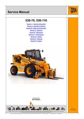
- 1. Copyright © 2004 JCB SERVICE. All rights reserved. No part of this publication may be reproduced, stored in a retrieval system, or transmitted in any form or by any other means, electronic, mechanical, photocopying or otherwise, without prior permission from JCB SERVICE. World Class Customer Support 9813/3850-2 Publication No. Issued by JCB Technical Publications, JCB Aftermarket Training, Woodseat, Rocester, Staffordshire, ST14 5BW, England. Tel +44 1889 591300 Fax +44 1889 591400 Service Manual 530-70, 530-110 Section 1 - General Information Section 2 - Operator’s Manual Section B - Body and Framework Section C - Electrics Section E - Hydraulics Section F - Transmission Section G - Brakes Section H - Steering Section K - Engine
- 2. Copyright © 2004 JCB SERVICE. All rights reserved. No part of this publication may be reproduced, stored in a retrieval system, or transmitted in any form or by any other means, electronic, mechanical, photocopying or otherwise, without prior permission from JCB SERVICE. World Class Customer Support 9813/3850-2 Publication No. Issued by JCB Technical Publications, JCB Aftermarket Training, Woodseat, Rocester, Staffordshire, ST14 5BW, England. Tel +44 1889 591300 Fax +44 1889 591400 Section 1 General Information Service Manual - 530-70, 530-110 Section 1 - General Information Section 2 - Operator’s Manual Section B - Body and Framework Section C - Electrics Section E - Hydraulics Section F - Transmission Section G - Brakes Section H - Steering Section K - Engine
- 3. Section 1 - General Information Contents 1-i 1-i Page No.Contents Introduction Identifying Your Machine ........................................................................... 1-1 Safety Introduction ................................................................................................ 1-3 Use Introduction ................................................................................................ 1-5 Scope ........................................................................................................ 1-6 Personnel ..............................................................................................1-6 Newest Data ..........................................................................................1-6 Format ....................................................................................................... 1-7 Left Side, Right Side ..............................................................................1-7 Hydraulic Schematic Codes ...................................................................... 1-8 Colour Codes ........................................................................................1-8 Routine Maintenance Maintenance Schedules ............................................................................ 1-9 Service Tools Numerical List .......................................................................................... 1-11 Section B ................................................................................................. 1-14 Section C ................................................................................................. 1-18 Section E ................................................................................................. 1-19 Section F ................................................................................................. 1-27 Section H ................................................................................................. 1-35 Section K ................................................................................................. 1-36 Service Aids Sealing and Retaining Compounds ......................................................... 1-37 Torque Settings Zinc Plated Fasteners and Dacromet Fasteners ..................................... 1-39 Introduction ..........................................................................................1-39 Bolts and Screws .................................................................................1-39 Hydraulic Connections ............................................................................. 1-43 'O' Ring Face Seal System ..................................................................1-43 'Torque Stop' Hose System .................................................................1-46 `Quick-Connect' Pilot Hoses .................................................................... 1-47 Disconnecting ......................................................................................1-47 Connecting ..........................................................................................1-47 General Procedures Introduction .............................................................................................. 1-49 Parking the Machine and Making it Safe ................................................. 1-50 Venting the Hydraulic Pressure ............................................................... 1-51 Connecting/Disconnecting Hydraulic Hoses ............................................ 1-52 Battery Disconnection/Connection .......................................................... 1-53 Removing and Replacing Components ................................................... 1-54 Preparation ..........................................................................................1-54 Original Components ...........................................................................1-54 New Components ................................................................................1-54 Torques and Fixings ............................................................................1-54 Battery Charging System Precautions ..................................................... 1-55
- 4. Section 1 - General Information Contents 1-ii 1-ii Page No.Contents Gas Hydraulic Bladder Accumulators ...................................................... 1-56 Replacement .......................................................................................1-56 Charging ..............................................................................................1-56
- 5. Section 1 - General Information 1-1 1-19813/3850-2 Introduction Identifying Your Machine For information about identifying your machine and its main components, refer to Operator’s Manual, Introduction, Identifying Your Machine.
- 6. Section 1 - General Information 1-3 1-39813/3850-2 Safety Introduction In this manual and on the machine there are safety notices. The safety notices have different signal words as follows: – DANGER – WARNING – CAUTION – Notice For an explanation of the safety notice signal words, refer to Section 2, Introduction, Safety. For general safety notices, refer to Section 2, Introduction, Safety Check List. For maintenance safety notices, refer to Section 2, Routine Maintenance, Health and Safety. For safety notices specific to maintenance procedures, refer to the relevant procedure. If you do not fully understand a safety notice ask your employer to explain it.
- 7. Maintenance Engine 139 9821/7850-2 139 Engine General Clean Warning! Airborne particles of light combustible material such as straw, grass, wood shavings, etc. must not be allowed to accumulate within the engine compartment or in the propshaft guards (when installed). Examine these areas frequently and clean at the beginning of each work shift or more often if required. Before opening the engine cover, make sure that the top is clear of debris. Notice: The engine or certain components could be damaged by high pressure washing systems; special precautions must be taken if the engine is to be washed using a high pressure system. Ensure that the engine air intake, alternator, starter motor and any other electrical components are shielded and not directly cleaned by the high pressure cleaning system. Notice: Clean the engine before you start engine maintenance. Obey the correct procedures. Contamination of the fuel system will cause damage and possible failure of the engine. Stop the engine and allow it to cool for at least one hour. Do not attempt to clean any part of the engine while it is running. Do not aim the water jet directly at oil seals or electrical and electronic components such as the ECU (Electronic Control Unit), alternator or fuel injectors. Before carrying out any service procedures that require components to be removed, the engine must be properly cleaned. Cleaning must be carried out either in the area of components to be removed or, in the case of major work, or work on the fuel system, the whole engine and surrounding machine must be cleaned. 1. Remove the undershield. Refer to: Maintenance > Access Apertures > Undershield (Page ). 2. Make sure that the electrical system is isolated. 3. Make sure that all electrical connectors are correctly coupled. If connectors are open fit the correct caps or seal with water proof tape. 4. Cover the alternator with a plastic bag to prevent water ingress. 5. Seal the engine air intake, exhaust and breather system. 6. Make sure that the oil filler caps and dipstick are correctly installed. 7. Use a low pressure water jet and brush to soak off caked mud or dirt. 8. Apply an approved cleaning and degreasing agent with a brush. Obey the manufacturers instructions. 9. Use a pressure washer to remove the soft dirt and oil. Do not place the jet nozzle closer to any part of the engine than the distance specified. Distance: 600mm 10. When the pressure washing is complete move the machine away from the wash area, or alternatively, clean away the material washed from the machine. 11. Before working on specific areas of the engine use a compressed air jet to dry off any moisture. When the area is dry use a soft clean brush to remove any sand or grit particles that remain. 12. When removing components be aware of any dirt or debris that may be exposed. Cover any open ports and clean away the deposits before proceeding. Check (Condition) Start the engine and check for:
- 8. Maintenance Engine 140 9821/7850-2 140 • Excessive smoke • Excessive vibration • Excessive noise • Overheating • Performance • Unusual smells. Oil Check (Leaks) Before you start the product, do a check for oil leaks: 1. Make the product safe. Refer to: Maintenance > Maintenance Positions (Page 124). 2. Get access to the engine compartment (if applicable) Refer to: Maintenance > Access Apertures (Page 130). 3. Check the engine and the area below for oil leaks. 4. Close the engine cover (if applicable). 5. If necessary, contact your JCB dealer. Check (Level) Notice: Do not exceed the correct level of engine oil in the sump. If there is too much engine oil, the excess must be drained to the correct level. An excess of engine oil could cause the engine speed to increase rapidly without control. 1. Make the product safe. Refer to: Maintenance > Maintenance Positions (Page 124). 2. Wait for the oil to drain back into the engine sump before you take a reading. If not, a false low reading may be recorded which can cause the engine to be overfilled. 3. Get access to the engine compartment (if applicable). Refer to: Maintenance > Access Apertures (Page 130). 4. Remove and clean the dipstick. Refer to: Maintenance > Service Points (Page 127). 5. Replace the dipstick. 6. Remove the dipstick. 7. Check the oil level. The oil should be between the two marks on the dipstick. 8. If necessary, add more oil: 8.1. Remove the filler cap. Refer to: Maintenance > Service Points (Page 127). 8.2. Add the recommended oil slowly through the filler point Refer to: Technical Data > Fluids, Lubricants and Capacities (Page 184). 8.3. Replace the dipstick. 8.4. Remove the dipstick. 8.5. Check the oil level, if necessary add more oil.
- 9. Maintenance Engine 141 9821/7850-2 141 8.6. Replace the dipstick 8.7. Replace the filler cap. 9. Close and secure the engine cover (if applicable). Replace Notice: Do not exceed the correct level of engine oil in the sump. If there is too much engine oil, the excess must be drained to the correct level. An excess of engine oil could cause the engine speed to increase rapidly without control. Warning! Hot oil and engine components can burn you. Make sure the engine is cool before doing this job. Used engine crankcase lubricants contain harmful contaminants. In laboratory tests it was shown that used engine oils can cause skin cancer. Caution! It is illegal to pollute drains, sewers or the ground. Clean up all spilt fluids and/or lubricants. Used fluids and/or lubricants, filters and contaminated materials must be disposed of in accordance with local regulations. Use authorised waste disposal sites. 1. Make the machine safe. Refer to: Maintenance > Maintenance Positions (Page 124). 2. Get access to the engine compartment. Refer to: Maintenance > Access Apertures (Page 130). 3. Remove the oil filler cap. Refer to: Maintenance > Service Points (Page 127). 4. Remove the engine oil drain plug. Drain the oil in to a suitable container. Refer to: Maintenance > Service Points (Page 127). 5. Clean the drain plug. Install the drain plug. Tighten the drain plug to the correct torque value. Refer to: Technical Data > Torque Values (Page 189). 6. Remove the cap from the oil filter housing (if applicable). 7. Remove and discard the oil filter cartridge. 8. Fit a new filter with new gaskets. 9. Fit and tighten the cover on the oil filter housing (if applicable). Tighten the cover to the correct torque value. Refer to: Technical Data > Torque Values (Page 189). 10. Add the correct specification and quantity of oil. Refer to: Technical Data > Fluids, Lubricants and Capacities (Page 184). 11. Check the oil level. Refer to: Maintenance > Engine > Oil > Check (Level) (Page 140). 12. Install the oil filler cap. 13. Close and secure the engine cover. 14. Operate the engine at idle speed until the oil pressure low warning light has extinguished and the new filter has primed before the engine speed is increased above idle speed. 15. Check for leaks. 16. Check the oil level when the oil has cooled. 16.1.Fill with clean engine oil, if necessary.
- 10. Maintenance Engine 142 9821/7850-2 142 Drive Belt Check (Condition) Warning! Do not try to turn the engine by pulling the fan or fan belt. This could cause injury or premature component failure. Caution! Make sure the engine cannot be started. Disconnect the battery before doing this job, otherwise you could be injured. The FEAD (Front End Accessory Drive) belt drives the alternator, water pump and the air conditioning compressor (if fitted). The belt is automatically kept in tension so will not need to be adjusted. At the recommended service interval, visually inspect the belt for damage: 1. Make the machine safe. Refer to: Maintenance > Maintenance Positions (Page 124). 2. Open the engine cover. Refer to: Maintenance > Access Apertures > Engine Compartment Cover (Page 130). 3. Remove the FEAD belt cover. 4. Inspect the belt for cracks, fraying or missing pieces. If necessary contact your JCB dealer for service requirements. 5. When maintenance is complete, make sure that the guard is installed. Do not operate the machine unless the guard is installed correctly. Refer to: Maintenance > Service Points (Page 127).
- 11. Maintenance Air Filter 143 9821/7850-2 143 Air Filter General Check (Condition) Notice: Do not modify or fit non JCB approved components to the engine induction system, otherwise the engine emissions will be compromised. 1. Make the machine safe. Refer to: Maintenance > Maintenance Positions (Page 124). 2. Get access to induction system. Refer to: Maintenance > Access Apertures (Page 130). 3. Check the system hoses for: 3.1. Condition. 3.2. Damage. 3.3. Security. 4. Replace the system hoses if necessary. Dust Valve Check (Condition) • Check the dust valve for rips/tears. • Check there are no obstructions. • Check that the dust valve is free of dirt and dust. • Check that the dust valve securely attached to the air filter housing.
- 12. Maintenance Fuel System 144 9821/7850-2 144 Fuel System General Bleed 1. Make the machine safe. Refer to: Maintenance > Maintenance Positions (Page 124). 2. Open the engine cover. Refer to: Maintenance > Access Apertures (Page 130). 3. Remove the fuel hose. Refer to Figure 97. Figure 97. A B A Fuel hose B Lift pump 4. Operate the fuel lift pump lever until all of the air has been released. 5. If the fuel does not move when you operate the lift pump lever, make sure the pump diaphragm is in correct position. 6. When all of the air has been released, connect the fuel hose. 7. Check all the O-ring seals and connections. 8. Close the engine cover. 9. Start the engine and run it at 1400-1500 rpm. 10. Make sure the engine operates smoothly and does not stop. If necessary, repeat the steps 1 to 8 procedure again. 11. Turn the ignition key to the off position. Check (Leaks) 1. Make the machine safe. Refer to: Maintenance > Maintenance Positions (Page 124). 2. Get access to the engine compartment (if applicable). Refer to: Maintenance > Access Apertures (Page 130). 3. Check the engine compartment (if applicable), fuel lines and the area below for leaks. 4. Start the engine.
- 13. Maintenance Fuel System 145 9821/7850-2 145 5. While the engine is running check the engine compartment (if applicable), fuel lines and the area below for leaks. 6. If necessary, contact your JCB dealer. Tank Clean Draining Fuel Tank Impurities 1. Make the machine safe. Refer to: Maintenance > Maintenance Positions (Page 124). 2. Get access to the fuel tank drain plug. Refer to: Maintenance > Service Points (Page 127). 3. Put a suitable container below the drain plug. 4. Remove the drain plug. 5. Drain the water and deposits until there is clean diesel. 6. Clean and install the drain plug. 7. Tighten the drain plug to correct torque value. Refer to: Technical Data > Torque Values (Page 189). Clean the Filler Cap 1. Make the machine safe. Refer to: Maintenance > Maintenance Positions (Page 124). 2. Get access to the fuel filler cap. Refer to: Maintenance > Service Points (Page 127). 3. Clean the exterior of the cap with a clean cloth. 4. Remove the fuel filler cap. 5. Clean the interior of the fuel filler cap with a clean cloth. 6. Install the fuel filler cap. Fuel Filter Replace 1. Make the machine safe. Refer to: Maintenance > Maintenance Positions (Page 124). 2. Get access to the filter. Refer to: Maintenance > Access Apertures (Page 130). 3. Drain and remove the separator bowl. Refer to: Maintenance > Fuel System > Water Separator (Page 146). 4. Replace the fuel filter. 5. Install the separator bowl.
- 14. Maintenance Fuel System 146 9821/7850-2 146 6. Bleed the fuel system. Refer to: Maintenance > Fuel System > General > Bleed (Page 144). Figure 98. A B A Filter B Bowl Water Separator Clean 1. Make the machine safe. Refer to: Maintenance > Maintenance Positions (Page 124). 2. Get access to the water separator. Refer to: Maintenance > Service Points (Page 127). 3. Check the water separator float position. 4. If the float has reached the red line, open the drain plug and drain the water. 5. Tighten the drain plug when all the water is drained.
- 15. Maintenance Fuel System 147 9821/7850-2 147 Figure 99. A B A Water separator B Maximum level - red line C Drain plug Main Fuel Filter 1. Make the machine safe. Refer to: Maintenance > Maintenance Positions (Page 124). 2. Get access to the main fuel filter. Refer to: Maintenance > Service Points (Page 127). 3. If there is water but no sediment, open the tap to drain the water. 4. If there is any sediment in the bowl replace the fuel filter element. Do not disconnect the water in fuel electrical connector.
- 16. Maintenance Fuel System 148 9821/7850-2 148 Figure 100. A B C A Main fuel filter B Bowl C Tap Secondary Fuel Filter 1. Make the machine safe. Refer to: Maintenance > Maintenance Positions (Page 124). 2. Get access to the secondary fuel filter. Refer to: Maintenance > Service Points (Page 127). 3. Open the tap to drain the water. 4. If there is any sediment in the bowl replace the fuel filter element. Figure 101. A B A Secondary fuel filter B Tap
- 17. Thank you very much for your reading. Please Click Here. Then Get COMPLETE MANUAL. NO WAITING NOTE: If there is no response to click on the link above, please download the PDF document first and then click on it.
- 18. Maintenance Cooling System 149 9821/7850-2 149 Cooling System General Check (Leaks) Before you start the machine, inspect the system for leaks: 1. Make the machine safe. Refer to: Maintenance > Maintenance Positions (Page 124). 2. Get access to the cooling pack. Refer to: Maintenance > Access Apertures (Page 130). 3. Check the cooling system for leaks. 4. If necessary, contact your JCB dealer. Coolant Check (Condition) Refer to: Technical Data > Fluids, Lubricants and Capacities > Coolant (Page 188). Check (Level) Caution! The cooling system is pressurised when the coolant is hot. When you remove the cap, hot coolant can spray out and burn you. Make sure that the engine is cool before you work on the cooling system. 1. Make the machine safe. 2. Let the engine cool. 3. Get access to the coolant expansion tank. Refer to: Maintenance > Service Points (Page 127). 4. Check the coolant level in the expansion tank. 4.1. Carefully loosen the cap on the expansion tank and let the pressure release from the system. Refer to: Maintenance > Service Points (Page 127). 4.2. Remove the cap from the expansion tank. 4.3. Add the recommended coolant up to the maximum mark. Refer to: Technical Data > Fluids, Lubricants and Capacities (Page 184). 4.4. Replace the cap. 5. Start the engine and run the engine up to operating temperature. 6. Stop the engine. 7. Remove the ignition key. 8. Check for leaks. Cooling Pack Clean 1. Make the machine safe. Do not stop the engine at this time. Refer to: Maintenance > Maintenance Positions (Page 124).
- 19. Maintenance Cooling System 150 9821/7850-2 150 2. Position the machine in a relatively clean area before reversing the fan to make sure that other debris is not drawn in. 3. Let the engine cool. 4. Get access to the radiator. Refer to: Maintenance > Access Apertures (Page 130). 5. Unlock the top door with ignition key and swing it as far as it can go. Refer to Figure 102. 6. Lift the bottom door slightly to free its catch bracket from the locating pin. Refer to Figure 102. 7. Pull the bottom door and let it hang on the hinges. Refer to Figure 102. Figure 102. A B A Top door B Bottom door 8. Push the fastener catch plate up. Refer to Figure 103. 9. Straighten the catch to allow the oil cooler to move forward to access the radiator. Refer to Figure 103.
- 20. Maintenance Cooling System 151 9821/7850-2 151 Figure 103. C D C Radiator D Fastener catch 10. Tilt the oil cooler away from the radiator. Refer to Figure 104. Figure 104. E F E Oil cooler F Radiator 11. Clean both sides of the oil cooler. 12. If necessary, use a soft bristle brush or compressed air to remove all debris from the oil cooler and radiator. 13. Push the oil cooler back into position and secure using the fastener catch. 14. To avoid fouling of hoses with the door, push the hoses in the radiator mounting plates. 15. Secure the hoses behind the sealing strips. 16. Close the bottom door. 17. Close the top door. Lock it using the ignition key. Check (Condition) 1. Make the machine safe. Refer to: Maintenance > Maintenance Positions (Page 124).