
Recommended
Recommended
More Related Content
More from ukdkksmmd
More from ukdkksmmd (20)
Recently uploaded
Recently uploaded (20)
JCB 412S 414S 416S WHEELED LOADER Service Repair Manual Instant Download.pdf
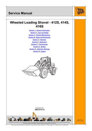
- 1. Copyright © 2004 JCB SERVICE. All rights reserved. No part of this publication may be reproduced, stored in a retrieval system, or transmitted in any form or by any other means, electronic, mechanical, photocopying or otherwise, without prior permission from JCB SERVICE. World Class Customer Support 9803/4170-14 Publication No. Issued by JCB Technical Publications, JCB Aftermarket Training, Woodseat, Rocester, Staffordshire, ST14 5BW, England. Tel +44 1889 591300 Fax +44 1889 591400 Service Manual Wheeled Loading Shovel - 412S, 414S, 416S Section 1 - General Information Section 2 - Care and Safety Section 3 - Routine Maintenance Section B - Body and Framework Section C - Electrics Section E - Hydraulics Section F - Transmission Section G - Brakes Section H - Hydraulic Steering Section K - Engine
- 2. Section 1 - General Information 1 - 0 1 - 0 9803/4170-10 Page left intentionally blank
- 3. Page No. Contents Section 1 - General Information 1 - i 1 - i Introduction About this Publication .............................................................................. 1 - 1 Identifying your Machine Identification Plates ................................................................................. 1 - 2 Torque Settings Zinc Plated Fasteners (golden finish) ...................................................... 1 - 5 JCB Standard Torque Settings B.S.P. Port Connection (Colour Coded) 1 - 6 JCB Standard Torque Settings for Hose Ends and Flanged Fittings (Colour Coded) ............................................................. 1 - 7 Service Tools Numerical List Section B - Body and Framework .................................... 1 - 8 Tool Detail Reference Section B - Body and Framework ........................ 1 - 9 Numerical List Section C - Electrics ...................................................... 1 - 13 Tool Detail Reference Section C - Electrics ........................................... 1 - 14 Numerical List Section E - Hydraulics ................................................... 1 - 15 Tool Detail Reference Section E- Hydraulics ......................................... 1 - 18 Numerical List Section F - Transmission ............................................... 1 - 22 Tool Detail Reference Section F - Transmission .................................... 1 - 23 Numerical List Section K - Engine ......................................................... 1 - 26 Tool Detail Reference Section K - Engine ............................................. 1 - 27 Service Consumables Sealing and Retaining Compounds ....................................................... 1 - 28
- 4. Page No. Contents Section 1 - General Information 1 - ii 1 - ii
- 5. Section 1 - General Information 1 - 1 1 - 1 9803/4170-10 Introduction About this Publication This publication is designed for the benefit of JCB Distributor Service Engineers who are receiving, or have received, training by JCB Technical Training Department. These personnel should have a sound knowledge of workshop practice, safety procedures, and general techniques associated with the maintenance and repair of hydraulic earthmoving equipment. Renewal of oil seals, gaskets, etc., and any component showing obvious signs of wear or damage is expected as a matter of course. It is expected that components will be cleaned and lubricated where appropriate, and that any opened hose or pipe connections will be blanked to prevent excessive loss of hydraulic fluid and ingress of dirt. Finally, please remember above all else SAFETY MUST COME FIRST! The manual is compiled in sections, the first three are numbered and contain information as follows: 1 General Information - includes torque settings and service tools. 2 Care & Safety - includes warnings and cautions pertinent to aspects of workshop procedures etc. 3 Routine Maintenance - includes service schedules and recommended lubricants for all the machine. The remaining sections are alphabetically coded and deal with Dismantling, Overhaul etc. of specific components, for example: The page numbering in each alphabetically coded section is not continuous. This allows for the insertion of new items in later issues of the manual. Section contents, technical data, circuit descriptions, operation descriptions etc. are inserted at the beginning of each alphabetically coded section. All sections are listed on the front cover; tabbed divider cards align directly with individual sections on the front cover for rapid reference. Where a torque setting is given as a single figure it may be varied by plus or minus 3%. Torque figures indicated are for dry threads, hence for lubricated threads may be reduced by one third. 'Left Hand' and 'Right Hand' are as viewed from the rear of the machine facing forwards. This Service Manual covers the following machines: 412S Wheeled Loading Shovel from machine serial number 535000 414S Wheeled Loading Shovel from machine serial number 537000 416S Wheeled Loading Shovel from machine serial number 543000 The information provided in this manual for the 414S machine also applies to the 416S machine except where speciified. Smoothshift Transmission introduced from the following serial numbers: 412S Wheeled Loading Shovel from machine serial number 535500 414S Wheeled Loading Shovel from machine serial number 537300 416S Wheeled Loading Shovel from machine serial number 543100 JCB 444 Series engine added to 412S Wheeled Loading Shovel from machine serial number 1242000. A Attachments B Body & Framework...etc.
- 6. Section 1 - General Information 1 - 2 1 - 2 9803/4170-10 Identifying your Machine Identification Plates Identification Plate Your machine has an identification plate 1X mounted on the left hand side of the machine on the loader arm pillar. The serial numbers of the machine and its major units are stamped on the plate. Fig 1. Explanation of Vehicle Identification Number (VIN) 1 World Manufacturer Identification, SLP = JCB 2 Machine Model, 412S0 = 412S 3 Year of Manufacture S, (P = 1993, R = 1994, S = 1995, T = 1996, V = 1997, W = 1998, X = 1999, Y = 2000, 1 = 2001, 2 = 2002, 3 = 2003, 4 = 2004) 4 Manufacturing Location (E = England) 5 Machine Serial Number (0527001) The serial number of each major unit is also stamped on the unit itself. If a major unit is replaced by a new one, the serial number on the identification plate will be wrong. Either stamp the new number of the unit on the identification plate, or simply stamp out the old number. This will prevent the wrong unit number being quoted when replacement parts are ordered. The machine and engine serial numbers can help identify exactly the type of equipment you have. Unit Identification The engine serial number is stamped on a plate 2Y or 3Y which is fastened to the right side of the cylinder block, near the fuel filter. Note: For machines with the JCB 444 Series engine, see Section K, Technical Data. Fig 2. 412S Machines 1 2 3 4 5 SLP 412S0 S E 0527001
- 7. Section 1 - General Information Identifying your Machine Identification Plates 1 - 3 1 - 3 9803/4170-10 Fig 3. 414S Machines Typical Engine Identification Number 1 Engine Type, a AA = 4 cylinder naturally aspirated b AB = 4 cylinder turbo 2 Build Number 3 Country of Origin 4 Engine Sequence Number 5 Year of Manufacture Transmission Identification The Transmission serial number is stamped on plate 4Z or 5Z as shown. Fig 4. 412S Machines 1 2 3 4 5 AA 50261 U 500405 P
- 8. Section 1 - General Information Identifying your Machine Identification Plates 1 - 4 1 - 4 9803/4170-10 Fig 5. 414S Machines
- 9. Section 1 - General Information 1 - 5 1 - 5 9803/4170-10 Torque Settings Zinc Plated Fasteners (golden finish) Use only where no torque setting is specified in the text. Values are for dry threads and may be within three per cent of the figures stated. For lubricated threads the values should be REDUCED by one third. UNF Grade `S' Bolts Metric Grade 8.8 Bolts Rivet Nut Bolts/Screws Note: All bolts used on JCB machines are high tensile and must not be replaced by bolts of a lesser tensile specification. Bolt size Torque Settings Dia. (mm) Hexagon Nm kgf m lbf ft (A/F) mm 1/4 6.3 7/16 14 1.4 10 5/16 7.9 1/2 28 2.8 20 3/8 9.5 9/16 49 5.0 36 7/16 11.1 5/8 78 8.0 58 1/2 12.7 3/4 117 12.0 87 9/16 14.3 13/16 170 17.3 125 5/8 15.9 15/16 238 24.3 175 3/4 19 1 1/8 407 41.5 300 7/8 22.2 1 5/16 650 66.3 480 1 25.4 1 1/2 970 99.0 715 1 1/4 31.7 1 7/8 1940 198.0 1430 1 1/2 38.1 2 1/4 3390 345.0 2500 Bolt size Torque Settings Dia. (mm) Hexagon Nm kgf m lbf ft (A/F) mm M5 (5) 8 7 0.7 5 M6 (6) 10 12 1.2 9 M8 (8) 13 28 3.0 21 M10 (10) 17 56 5.7 42 M12 (12) 19 98 10 72 M16 (16) 24 244 25 180 M18 (18) 27 350 36 258 M20 (20) 30 476 48 352 M24 (24) 36 822 84 607 M30 (30) 46 1633 166 1205 M36 (36) 55 2854 291 2105 Bolt size Torque Settings (for steel rivet nuts) Dia. (mm) Nm kgf m lbf ft M3 (3) 1.2 0.12 0.9 M4 (4) 3.0 0.3 2.0 M5 (5) 6.0 0.6 4.5 M6 (6) 10.0 1.0 7.5 M8 (8) 24.0 2.5 18.0 M10 (10) 48.0 4.9 35.5 M12 (12) 82.0 8.4 60.5
- 10. Section 1 - General Information Torque Settings JCB Standard Torque Settings B.S.P. Port Connection (Colour Coded) 1 - 6 1 - 6 9803/4170-10 JCB Standard Torque Settings B.S.P. Port Connection (Colour Coded) Note: All adapters, elbows and hoses should be tightened to JCB standard torque settings unless stated otherwise. Fig 1.
- 11. Section 1 - General Information Torque Settings JCB Standard Torque Settings for Hose Ends and Flanged Fittings (Colour Coded) 1 - 7 1 - 7 9803/4170-10 JCB Standard Torque Settings for Hose Ends and Flanged Fittings (Colour Coded) Note: All adapters, elbows and hoses should be tightened to JCB standard torque settings unless stated otherwise. Fig 2.
- 12. Section 1 - General Information 1 - 8 1 - 8 9803/4170-10 Service Tools Numerical List Section B - Body and Framework The tools listed in the table are special tools required for removal and replacement of Body and Framework parts. These tools are available from JCB Service. Note: Tools other than those listed will be required. It is expected that such general tools will be available in any well equipped workshop or be available locally from any good tool supplier. Part Number Description Tool Detail Reference 825/99849 Dummy Boss K Fig 12. ( T 1-11) 825/99850 Bearing Locator K Fig 12. ( T 1-11) 826/01179 M6 x 16mm Rivet Nut K Fig 1. ( T 1-9) 826/01106 M6 x 19mm Rivet Nut K Fig 1. ( T 1-9) 826/01177 M8 x 18mm Rivet Nut K Fig 1. ( T 1-9) 826/01176 M10 x 23mm Rivet Nut K Fig 1. ( T 1-9) 826/01333 M10 x 26mm Rivet Nut K Fig 1. ( T 1-9) 892/00842 Glass Lifter K Fig 3. ( T 1-9) 892/00843 Glass Stand K Fig 2. ( T 1-9) 892/00844 Long Knife K Fig 11. ( T 1-11) 892/00846 Glass Extractor (Handles) K Fig 8. ( T 1-10) 892/00847 Nylon Spatula K Fig 4. ( T 1-9) 892/00848 Wire Starter K Fig 6. ( T 1-10) 892/00849 Braided Cutting Wire K Fig 10. ( T 1-11) 926/15500 Rubber Spacer Blocks K Fig 5. ( T 1-10) 992/12800 Cut-Out Knife K Fig 7. ( T 1-10) 992/12801 'L' Blades K Fig 9. ( T 1-11)
- 13. Section 1 - General Information Service Tools Tool Detail Reference Section B - Body and Framework 1 - 9 1 - 9 9803/4170-10 Tool Detail Reference Section B - Body and Framework Fig 1. Note: 826/01179 M6 x 16mm Rivet Nut, 826/01106 M6 x 19mm Rivet Nut, 826/01177 M8 x 18mm Rivet Nut, 826/01176 M10 x 23mm Rivet Nut, 826/01333 M10 x 26mm Rivet Nut Installation Tool Available from: Bollhoff Fastenings Ltd. Midacre The Willenhall Estate Rose Hill Willenhall West Midlands, WV13 2JW Fig 2. 892/00843 Note: essential for preparing new glass prior to installation. Fig 3. 892/00842 Note: - minimum 2 off - essential for glass installation, 2 required to handle large panes of glass. Ensure suction cups are protected from damage during storage. Fig 4. 892/00847 Note: - general tool used for smoothing sealants - also used to re-install glass in rubber glazing because metal tools will chip the glass edge.
- 14. Section 1 - General Information Service Tools Tool Detail Reference Section B - Body and Framework 1 - 10 1 - 10 9803/4170-10 Fig 5. 926/15500 Note: - used to provide the correct set clearance between glass edge and cab frame. (unit quantity = 500 off) Fig 6. 892/00848 Note: - used to access braided cutting wire (below) through original polyurethane seal. Fig 7. 992/12800 Note: - used to remove broken glass. Fig 8. 892/00846 Note: - used with braided cutting wire (below) to cut out broken glass.
- 15. Section 1 - General Information Service Tools Tool Detail Reference Section B - Body and Framework 1 - 11 1 - 11 9803/4170-10 Fig 9. 992/12801 Note: - 25 mm (1 in) cut - replacement blades for cut-out knife (above), (unit quantity = 5 off) Fig 10. 892/00849 Note: - consumable heavy duty cut-out wire used with the glass extraction tool (above), (approx 25 m length) Fig 11. 892/00844 Note: - used to give extended reach for normally inaccessible areas. Fig 12. 825/99849 Note: - used with bearing locator to set up Upper Centre Pivot. Fig 13. 825/99850 Note: - used with dummy bush to set up Upper Centre Pivot.
- 16. Section 1 - General Information Service Tools Tool Detail Reference Section B - Body and Framework 1 - 12 1 - 12 9803/4170-10 Fig 14. Cab Prop Note: - used to support cab in the raised position. A minimum of 2 are required to support the side where work is being carried out. It is recommended that 4 are used to support the cab level. Manufacture from mild steel. Tube wall and plate minimum thickness must be 3 mm.
- 17. Section 1 - General Information Service Tools Numerical List Section C - Electrics 1 - 13 1 - 13 9803/4170-10 Numerical List Section C - Electrics The tools listed in the table are special tools required for testing electrics. These tools are available from JCB Service . Note: Tools other than those listed will be required. It is expected that such general tools will be available in any well equipped workshop or be available locally from any good tool supplier. Part Number Description Tool Detail Reference 892/00282 Shunt K Fig 15. ( T 1-14) 892/00283 Tool Kit Case K Fig 15. ( T 1-14) 892/00284 Digital Tachometer K Fig 15. ( T 1-14) 892/00285 Hyd. Oil Temperature Probe K Fig 15. ( T 1-14) 892/00286 Surface Temperature Probe K Fig 15. ( T 1-14) 892/00298 Fluke Meter K Fig 15. ( T 1-14) 993/85700 Battery Tester K Fig 16. ( T 1-14)
- 18. Section 1 - General Information Service Tools Tool Detail Reference Section C - Electrics 1 - 14 1 - 14 9803/4170-10 Tool Detail Reference Section C - Electrics Fig 15. 1 892/00283 Tool Kit Case 2 892/00298 Fluke Meter 3 892/00286 Surface Temperature Probe 4 892/00284 Venture Microtach Digital Tachometer 5 892/00282 100 amp Shunt - open type 6 892/00285 Hydraulic Temperature Probe Fig 16. 993/85700
- 19. Section 1 - General Information Service Tools Numerical List Section E - Hydraulics 1 - 15 1 - 15 9803/4170-10 Numerical List Section E - Hydraulics The tools listed in the table are special tools required for testing, removing and replacing hydraulics. These tools are available from JCB Service . Note: Tools other than those listed will be required. It is expected that such general tools will be available in any well equipped workshop or be available locally from any good tool supplier. Part Number Description Tool Detail Reference 1406/0011 Bonded Washer K Fig 19. ( T 1-18) 1406/0014 Bonded Washer K Fig 19. ( T 1-18) 1406/0018 Bonded Washer K Fig 19. ( T 1-18) 1406/0021 Bonded Washer K Fig 19. ( T 1-18) 1406/0029 Bonded Washer K Fig 19. ( T 1-18) 1604/0006 Adapter K Fig 20. ( T 1-18) 1612/0006 Adapter K Fig 20. ( T 1-18) 816/00189 Blanking Cap K Fig 22. ( T 1-19) 816/00190 Blanking Cap K Fig 22. ( T 1-19) 816/00193 Blanking Cap K Fig 22. ( T 1-19) 816/00196 Blanking Cap K Fig 22. ( T 1-19) 816/00197 Blanking Cap K Fig 22. ( T 1-19) 816/00294 Blanking Cap K Fig 22. ( T 1-19) 816/15118 Pressure Test Adapter K Fig 23. ( T 1-19) 816/20008 Adapter K Fig 20. ( T 1-18) 816/55038 Pressure Test Adapter K Fig 18. ( T 1-18) 816/55040 Pressure Test Adapter K Fig 18. ( T 1-18) 892/00039 Spool Clamp K Fig 26. ( T 1-20) 892/00055 Blanking Plug K Fig 21. ( T 1-19) 892/00056 Blanking Plug K Fig 21. ( T 1-19) 892/00057 Blanking Plug K Fig 21. ( T 1-19) 892/00058 Blanking Plug K Fig 21. ( T 1-19) 892/00059 Blanking Plug K Fig 21. ( T 1-19) 892/00060 Blanking Plug K Fig 21. ( T 1-19) 892/00074 Female Connector K Fig 24. ( T 1-19) 892/00075 Female Connector K Fig 24. ( T 1-19) 892/00076 Female Connector K Fig 24. ( T 1-19) 892/00077 Female Connector K Fig 24. ( T 1-19) 892/00137 Micro-Bore Hose K Fig 27. ( T 1-20) 892/00223 Hand Pump K Fig 27. ( T 1-20) 892/00239 Charging Tool K Fig 28. ( T 1-20)
- 20. Section 1 - General Information Service Tools Numerical List Section E - Hydraulics 1 - 16 1 - 16 9803/4170-10 892/00253 Pressure Test Kit K Fig 17. ( T 1-18) 892/00255 Pressure Test Adaptor K Fig 23. ( T 1-19) 892/00256 Pressure Test Adaptor K Fig 23. ( T 1-19) 892/00257 Pressure Test Adaptor K Fig 23. ( T 1-19) 892/00258 Pressure Test Adaptor K Fig 23. ( T 1-19) 892/00259 Pressure Test Adaptor K Fig 23. ( T 1-19) 892/00260 Pressure Test Adaptor K Fig 23. ( T 1-19) 892/00261 Pressure Test Adaptor K Fig 23. ( T 1-19) 892/00262 Pressure Test Adaptor K Fig 27. ( T 1-20) 892/00263 Pressure Test Adaptor K Fig 18. ( T 1-18) 892/00264 Pressure Test Adaptor K Fig 18. ( T 1-18) 892/00265 Pressure Test Adaptor K Fig 18. ( T 1-18) 892/00268 Flow Monitoring Unit K Fig 20. ( T 1-18) 892/00269 Sensor Head K Fig 20. ( T 1-18) 892/00270 Load Valve K Fig 20. ( T 1-18) 892/00274 Adapter K Fig 27. ( T 1-20) 892/00275 Adapter K Fig 20. ( T 1-18) 892/00279 Gauge K Fig 27. ( T 1-20) 892/00309 A.R.V. Pressure Test Kit K Fig 29. ( T 1-21) 892/00335 A.R.V. Cartridge Removal Tool K Fig 29. ( T 1-21) 892/00340 Test Block Body K Fig 29. ( T 1-21) 892/00341 Setting Body K Fig 29. ( T 1-21) 892/00343 Spanner K Fig 29. ( T 1-21) 892/00345 Anti-cavitation Lock Out Bung K Fig 29. ( T 1-21) 892/00706 Test Probe K Fig 27. ( T 1-20) 892/00948 Charging Tool K Fig 28. ( T 1-20) 892/01042 Charging Tool K Fig 28. ( T 1-20) 892/01043 Adapter K Fig 28. ( T 1-20) 992/09300 Spanner K Fig 25. ( T 1-20) 992/09400 Spanner K Fig 25. ( T 1-20) 992/09500 Spanner K Fig 25. ( T 1-20) 992/09600 Spanner K Fig 25. ( T 1-20) 992/09700 Spanner K Fig 25. ( T 1-20) 992/10000 Spanner K Fig 25. ( T 1-20) 992/10100 Spool Clamp K Fig 26. ( T 1-20) 993/68300 Adjusting Pin K Fig 29. ( T 1-21) Part Number Description Tool Detail Reference
- 21. Section 1 - General Information Service Tools Numerical List Section E - Hydraulics 1 - 17 1 - 17 9803/4170-10 The following parts are replacement items for kits and would normally be included in the kit numbers above. Replacement items for kit no. 892/00253 Part Number Description Tool Detail Reference 892/00201 Replacement Gauge K Fig 17. ( T 1-18) 892/00202 Replacement Gauge K Fig 17. ( T 1-18) 892/00203 Replacement Gauge K Fig 17. ( T 1-18) 892/00254 Replacement Hose K Fig 17. ( T 1-18)
- 22. Section 1 - General Information Service Tools Tool Detail Reference Section E- Hydraulics 1 - 18 1 - 18 9803/4170-10 Tool Detail Reference Section E- Hydraulics Fig 17. Hydraulic Circuit Pressure test Kit 892/00253 Pressure Test Kit 892/00201 Replacement gauge 0-20 bar (0-300 lbf/in2 ) 892/00202 Replacement gauge 0-40 bar (0-600 lbf/in2) 892/00203 Replacement gauge 0-400 bar (0-6000 lbf/ in2) 892/00254 Replacement Hose Fig 18. Pressure Test `T' Adapters 892/00262 1/4 in BSP x 1/4 in F BSP x Test Point 816/55038 3/8 in M BSP x 3/8 in F BSP x Test Point 816/55040 1/2 in M BSP x 1/2 in F BSP x Test Point 892/00263 5/8 in BSP x 5/8 in F BSP x Test Point 892/00264 3/4 in BSP x 3/4 in F BSP x Test Point 892/00265 1 in M BSP x 1 in F BSP x Test Point Fig 19. Bonded Washers 1406/0011 1/4 in BSP 1406/0018 1/2 in BSP 1406/0014 5/8 in BSP 1406/0021 3/4 in BSP 1406/0029 1.1/4 in BSP Fig 20. Flow Test Equipment 892/00268 Flow Monitoring Unit 892/00269 Sensor Head 0 to 100 l/min (0 to 22 UK gal/min) 892/00270 Load Valve 1406/0021Bonded Washer
- 23. Section 1 - General Information Service Tools Tool Detail Reference Section E- Hydraulics 1 - 19 1 - 19 9803/4170-10 1604/0006 Adapter 3/4 in M x 3/4 M BSP 1612/0006 Adapter 3/4 in F x 3/4 M BSP 816/20008 Adapter 3/4 in F x 1/2 M BSP 892/00275 Adapter 1/2 in F x 3/4 M BSP Fig 21. Female Cone Blanking Cap 892/00055 1/4 in BSP 892/00056 3/8 in BSP 892/00057 1/2 in BSP 892/00058 5/8 in BSP 892/00059 3/4 in BSP 892/00060 1 in BSP Fig 22. Male Cone Blanking Cap 816/00294 1/4 in BSP 816/00189 3/8 in BSP 816/00190 1/2 in BSP 816/00197 5/8 in BSP 816/00196 3/4 in BSP 816/00193 1 in BSP Fig 23. Pressure Test Adapters 892/00255 1/4 in BSP x Test Point 892/00256 3/8 in BSP x Test Point 892/00257 1/2 in BSP x Test Point 892/00258 5/8 in BSP x Test Point 816/15118 3/4 in BSP x Test Point 892/00259 1 in BSP x Test Point 892/00260 1.1/4 in BSP x Test Point 892/00261 5/8 in UNF x Test Point Fig 24. Female Connectors 892/00074 3/8 in BSP x 3/8 in BSP 892/00075 1/2 in BSP x 1/2 in BSP 892/00076 5/8 in BSP x 5/8 in BSP 892/00077 3/4 in BSP x 3/4 in BSP
- 24. Section 1 - General Information Service Tools Tool Detail Reference Section E- Hydraulics 1 - 20 1 - 20 9803/4170-10 Fig 25. Hexagon Spanners for Ram Pistons and End Caps 992/09300 55 mm 992/09400 65 mm 992/09500 75 mm 992/09600 85 mm 992/09700 95 mm 992/10000 125 mm Fig 26. Spool Clamps 892/00039 Spool Clamp 992/10100 Spool Clamp Fig 27. Hand Pump Equipment 892/00223 Hand Pump 892/00137 Micro-bore Hose 1/4 in BSP x 5 metres 892/00274 Adapter 1/4 in. M BSP x 3/8 in. M BSP Taper 892/00262 1/4 in M BSP x 1/4 in F BSP x Test Point 892/00706 Test Probe 892/00279 Gauge 0 - 400 bar (0 - 6000 lbf/in2 ) Fig 28. Accumulator Charge Equipment 892/00239 Charging Tool (Diaphragm Accumulators) 892/01042 Charging Tool (Diaphragm Accumulators) 892/01043 Adatper (use with 892/01042) 892/00948 Charging Tool (Piston Accumulators)
- 25. Section 1 - General Information Service Tools Tool Detail Reference Section E- Hydraulics 1 - 21 1 - 21 9803/4170-10 Fig 29. Components for Valve Block A.R.V. Testing 892/00309 A.R.V. Pressure Test Kit 1 892/00340 Test Block Body 2 892/00341 Setting Body 3 993/68300 Adjusting Pin 4 892/00343 Spanner 5 892/00345 Anti-cavitation Lock Out Bung 6 892/00335 A.R.V. Cartridge Removal Tool
- 26. Section 1 - General Information Service Tools Numerical List Section F - Transmission 1 - 22 1 - 22 9803/4170-10 Numerical List Section F - Transmission The tools listed in the table are special tools required for removal and replacement of Body and Framework parts. These tools are available from JCB Service. Note: Tools other than those listed will be required. It is expected that such general tools will be available in any well equipped workshop or be available locally from any good tool supplier. Part Number Description Tool Detail Reference 892/00817 Heavy Duty Socket K Fig 31. ( T 1-23) 892/00818 Heavy Duty Socket K Fig 31. ( T 1-23) 892/00819 Heavy Duty Socket K Fig 31. ( T 1-23) 892/00859 Spanner Stake Nut K Fig 34. ( T 1-24) 892/00860 Bearing Shim Remover K Fig 37. ( T 1-24) 892/00861 Bearing Remover Base Tool K Fig 37. ( T 1-24) 892/00862 Tab Washer Fitting Tool K Fig 34. ( T 1-24) 892/00863 Blanking Plate Fitting Tool K Fig 38. ( T 1-24) 892/00864 PD90 Locknut Spanner K Fig 36. ( T 1-24) 892/00865 Computer Test Harness K Fig 33. ( T 1-23) 892/00866 Computer Test Indicator Box K Fig 33. ( T 1-23) 892/00867 Computer Test Interrogator Box K Fig 33. ( T 1-23) 892/00891 Fitting Tool Assembly K Fig 39. ( T 1-24) 892/00909 Hub Puller K Fig 36. ( T 1-24) 892/01066 Interrogation lead K Fig 40. ( T 1-25) 992/04000 Torque Multiplier K Fig 32. ( T 1-23) 992/07603 Replacer - Bearing Cup K Fig 30. ( T 1-23)
- 27. Section 1 - General Information Service Tools Tool Detail Reference Section F - Transmission 1 - 23 1 - 23 9803/4170-10 Tool Detail Reference Section F - Transmission Fig 30. 992/07603 Fig 31. Heavy Duty Socket for Durlock Bolts 892/00817 17 mm A/F x 3/4 in. Square Drive 892/00818 22 mm A/F x 3/4 in. Square Drive 892/00819 15 mm A/F x 1/2 in. Square Drive Fig 32. 992/04000 Note: Use in conjunction with a torque wrench to give a 5:1 multiplication when tightening pinion nuts etc. Fig 33. 892/00865 Computer test harness 892/00866 Computer test indicator box 892/00867 Computer test interrogator box
- 28. Section 1 - General Information Service Tools Tool Detail Reference Section F - Transmission 1 - 24 1 - 24 9803/4170-10 Fig 34. 892/00859 Fig 35. 892/00862 Fig 36. 892/00864 Fig 37. 1 892/00860 Bearing Remover Shim 2 892/00861 Bearing Remover Base Tool Fig 38. 892/00863 Fig 39. 892/00891
- 29. Suggest: If the above button click is invalid. Please download this document first, and then click the above link to download the complete manual. Thank you so much for reading
- 30. Section 1 - General Information Service Tools Tool Detail Reference Section F - Transmission 1 - 25 1 - 25 9803/4170-10 Fig 40. 892/01066 Fig 41. 892/01066