Download to read offline
![International Research Journal of Engineering and Technology (IRJET) e-ISSN: 2395-0056
Volume: 05 Issue: 11 | Nov 2018 www.irjet.net p-ISSN: 2395-0072
© 2018, IRJET | Impact Factor value: 7.211 | ISO 9001:2008 Certified Journal | Page 660
preferably IGBT since IGBT is naturally commutated. Each
IGBT used in inverter have separate control over them and
also an electrical isolation from the controller. Here we are
incorporating a snubber circuit for the protection of IGBT.
Snubbers are used to suppress the voltage spikes which
occur in the equipment, in this case IGBT
5. PWM PULSE GENERATION
In this method, the inverter is not operating with a
constant frequency. A single inverter is generating
different frequency components. Pulses are generated in
such a way that voltage source inverter will generate the
same output waveform as that of VFD output waveform
except for fundamental frequency component. The output
of an inverter is injected into the VFD output with a 180
phase shift. The output of inverter will compensate the
current harmonics at the output of VFD. PWM pulses are
generated using the feedback of FFT computation. Higher
the frequency of inverter better the current compensation
Fig-2: Flow chart
6. CONCLUSION
A current harmonic injection technique is used to cut back
harmonics from induction motor drive that is discussed in
this paper. VFD generates completely different harmonics
that causes heating of motor, the introduction of EMI,
malfunctioning of measure instrumentality. Harmonic
distortion mostly occurs wherever loads withdrew non-
sinusoidal current from the system. The voltage provided
by an influence system is mostly not a pure sine wave.
7. ACKNOWLEDGEMENT
I would like to extend my warm gratitude to all the
persons who helped me to complete this paper. I am
highly grateful to my guide and other staffs for their
constant support and guidance.
8. REFERENCES
[1] HaoranBai, "A Three Order Harmonic Injection Method
to Reduce Current Harmonics for High-Speed PM
Generator", IEEE International Symposium on Power
Electronics for Distributed Generation Systems, 2010
[2] Konstantinos G.G., Panagis N.V., Nicholas A.V.,
"Harmonic Reduction Method for a Single-Phase DC AC
Converter Without an Output Filter", IEEE Transactions on
Power Electronics, Vol. 29, No. 9, September 2014
[3] MichailVasiladiotis, Alfred Rufer, "Dynamic Analysis
and State Feedback Voltage Control of Single-Phase Active
Rectifiers with DC-Link Resonant Filters", IEEE
Transactions on Power Electronics, Vol. 29, No. 10,
October 2014.
[4] Sehwan Kim, Jul-Ki Seok, "Induction Motor Control
With a Small DC-Link Capacitor Inverter Fed by Three-
Phase Diode Front-end Rectifiers", IEEE Transactions on
Power Electronics, Vol. 30, No. 5, May 2015.
[5] Ali. M. Eltamaly, "A Novel Harmonic Reduction
Technique for Controlled Converter by Third Harmonic
Current Injection", IEEE International Conference on
Control System, Computing and Engineering, Penang,
Malaysia, 23-25 November 2012](https://image.slidesharecdn.com/irjet-v5i11127-181201084533/75/IRJET-Harmonics-Reduction-using-Harmonics-Injection-Method-3-2048.jpg)

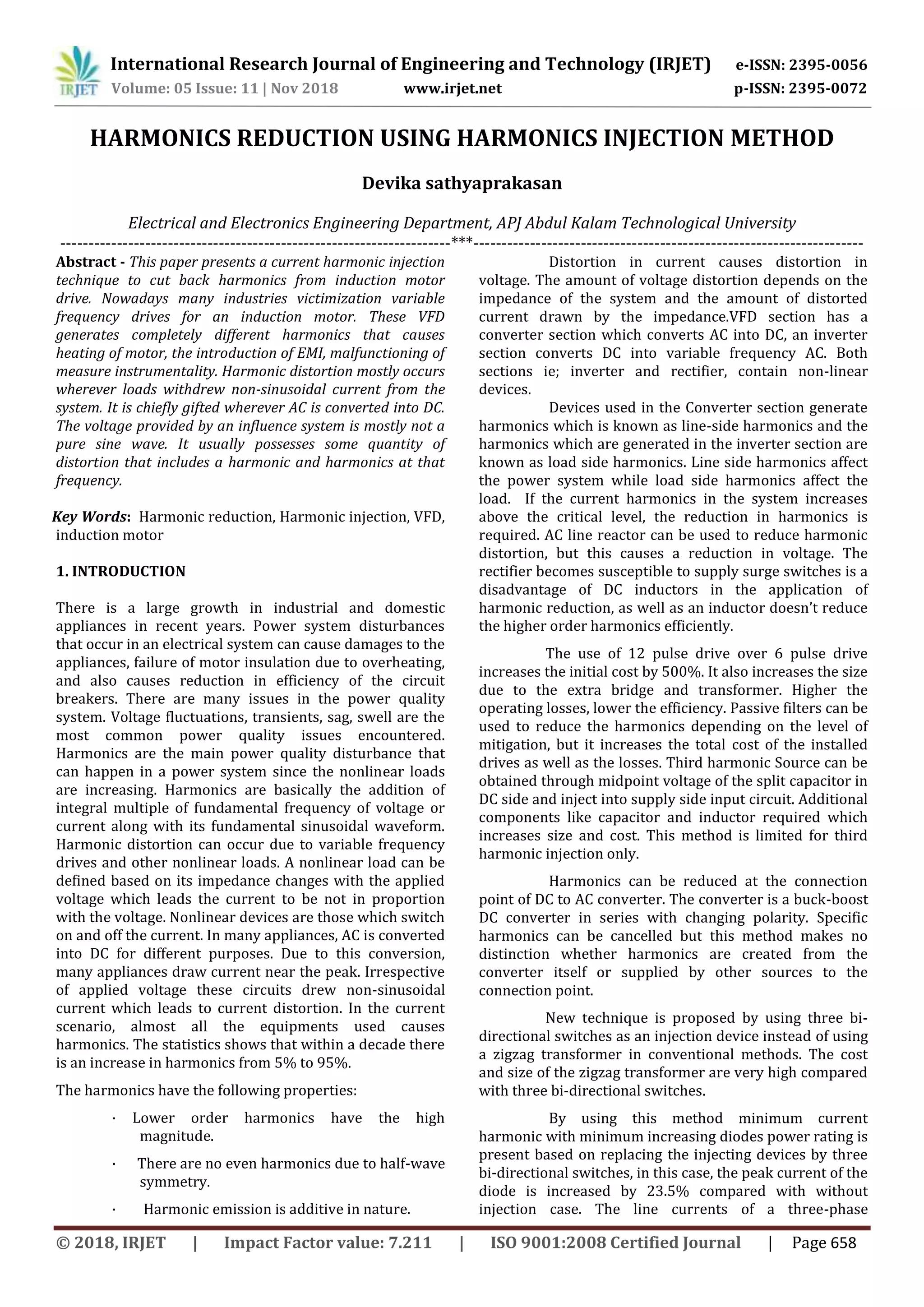
This document discusses a current harmonic injection technique to reduce harmonics from induction motor drives used in variable frequency drives (VFDs). VFDs generate harmonics that can cause motor heating, electromagnetic interference, and instrument malfunctions. The technique injects specific harmonics from an inverter circuit into the VFD output to cancel out current harmonics and reduce total harmonic distortion. It uses three bi-directional switches in the injection circuit instead of a traditional zigzag transformer to lower costs and size. Simulation results showed the technique reduced harmonics with a minimal increase in diode power ratings.


![P010439497.jeee [zsep02]](https://cdn.slidesharecdn.com/ss_thumbnails/p010439497-160706050110-thumbnail.jpg?width=640&height=640&fit=bounds)


