Downloaded 749 times

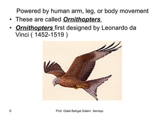
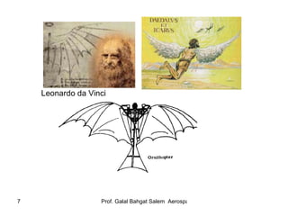
![Why Don’t Ornithopters Work? G. A. Borelli (1680 ) realized the fact that ( power/weight) ratio of a man is much less than that of bird Hence man will never be able to fly like a bird, by his own power only 2. Lighter-than-Air Balloons[Unpowered Flight] ● Firstly hot air balloons discovered by the Montgolfier Brothers in France (1783)](https://image.slidesharecdn.com/introductiontoflight1-110226120915-phpapp01/85/Introduction-to-flight-1-8-320.jpg)
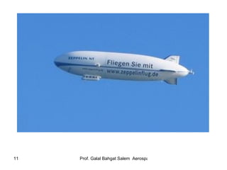
![3. Lighter-than-Air Dirigibles (Airships)[Powered] ● Firstly invented by Count von Zeppelin in Germany (1900) ● They are more rigid (the first airframe) than balloons, controlled and directed (using stabilizing surfaces) and propeller droved ● Large bags of gas inside the rigid airframe ● Count von Zeppelin (1929), flew around the world in 21 days ● Hydrogen fired in “Hindenburg” dirigible in 1937](https://image.slidesharecdn.com/introductiontoflight1-110226120915-phpapp01/85/Introduction-to-flight-1-10-320.jpg)
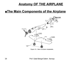
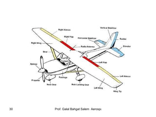
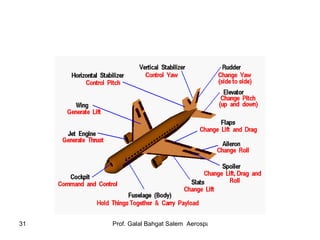
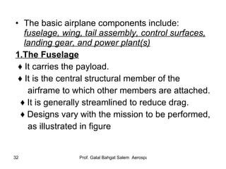
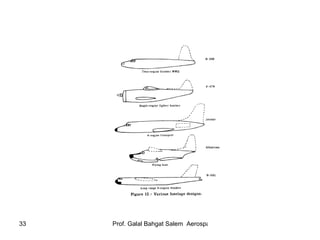
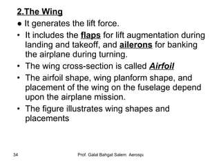
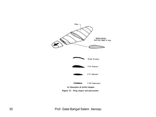
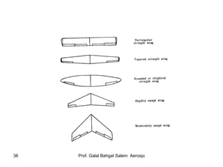
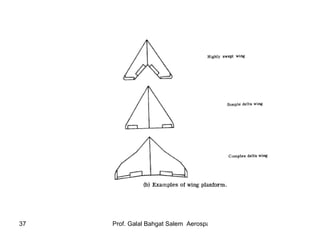
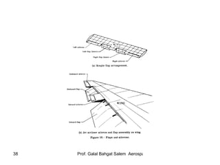
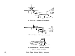
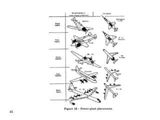
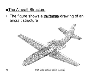
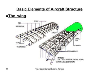
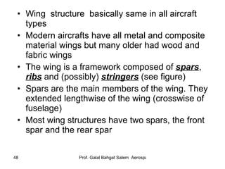
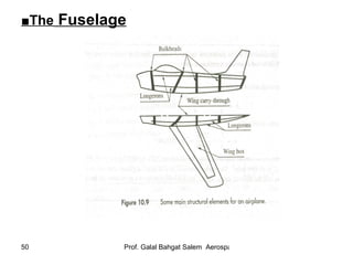
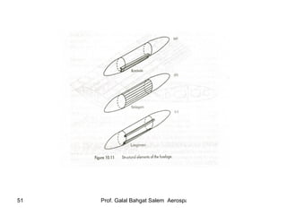


The document provides an overview of an introductory aeronautics course, including: - Course details like instructor, textbook, term work and exams - Topics covered across two terms like history of flight, aerodynamics, airfoils, and aircraft performance and stability - A brief history of the development of flight from early attempts to imitate birds to modern airplanes - Descriptions of key aircraft components like the fuselage, wings, tail assembly, landing gear, and power plants


