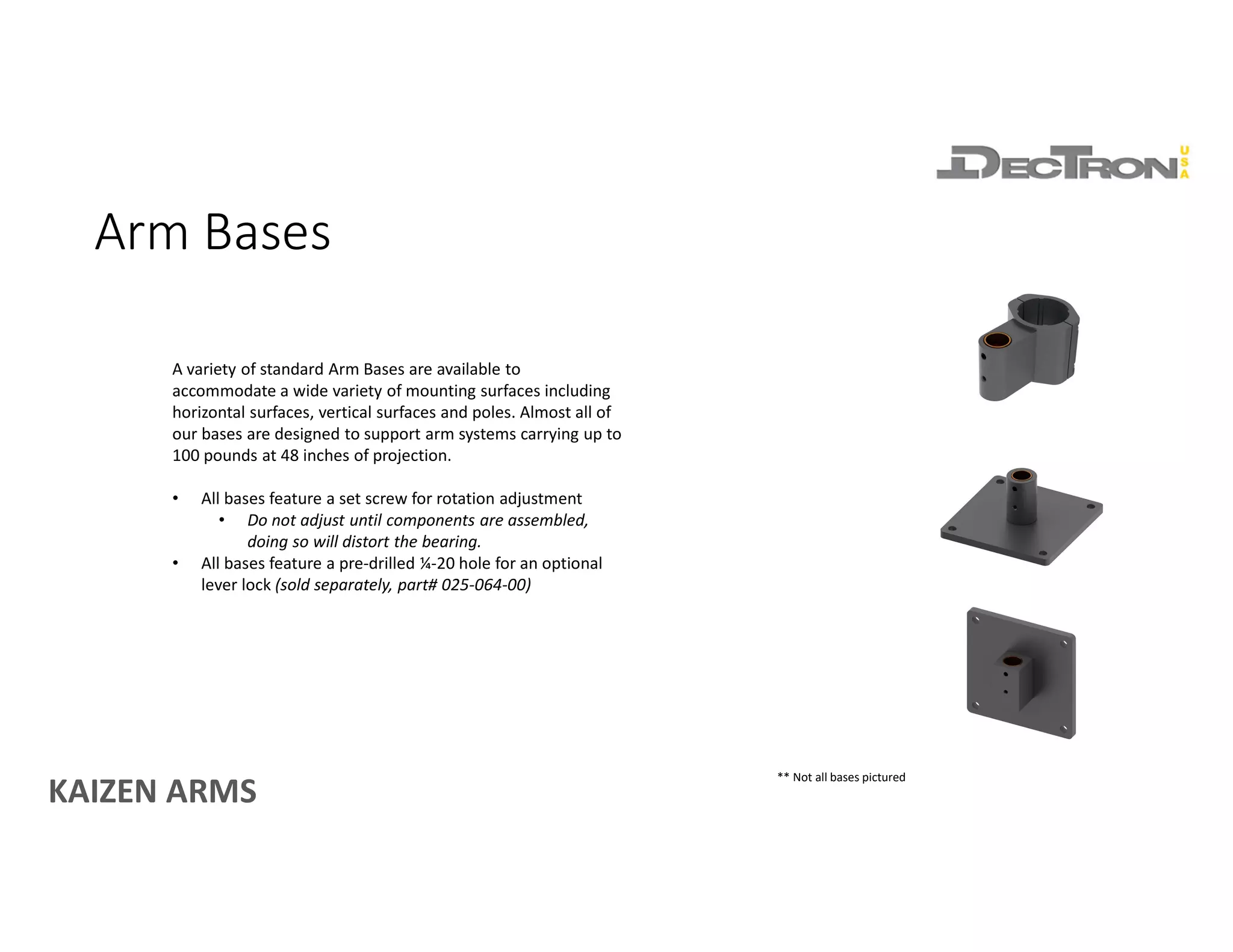
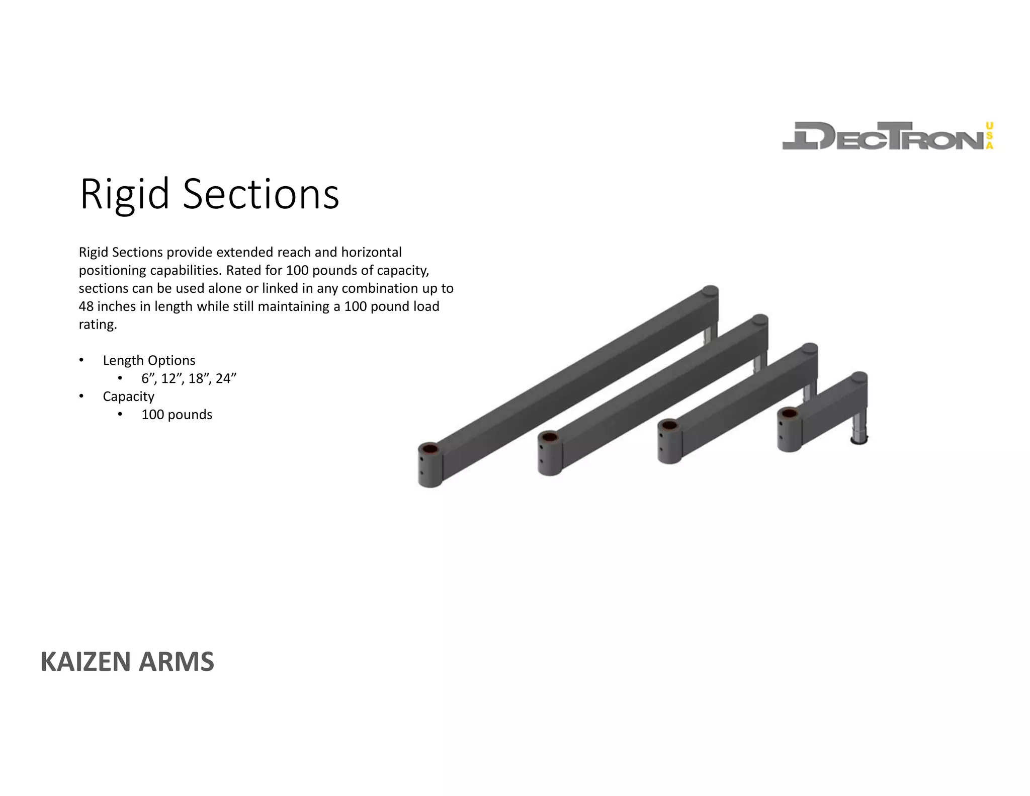
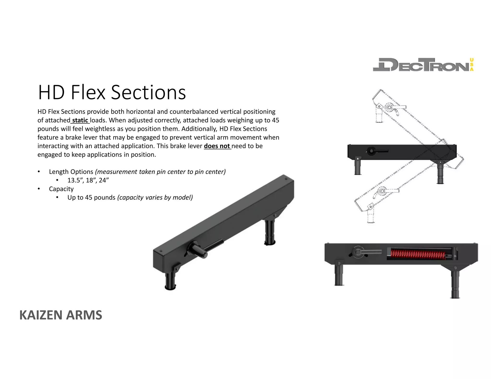
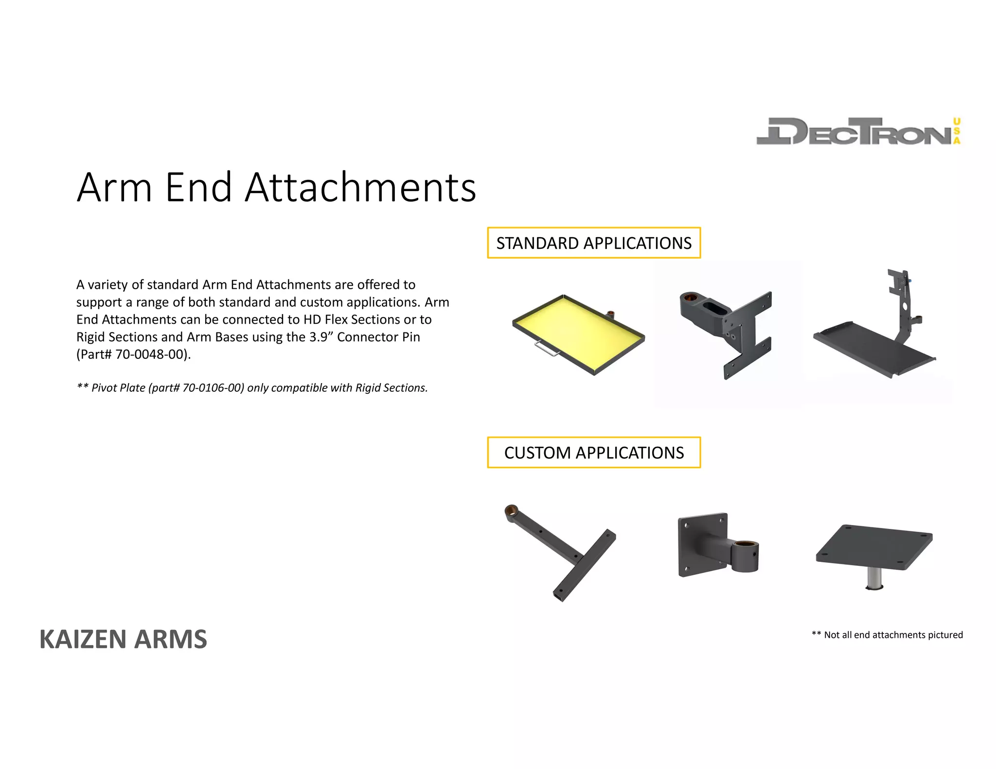
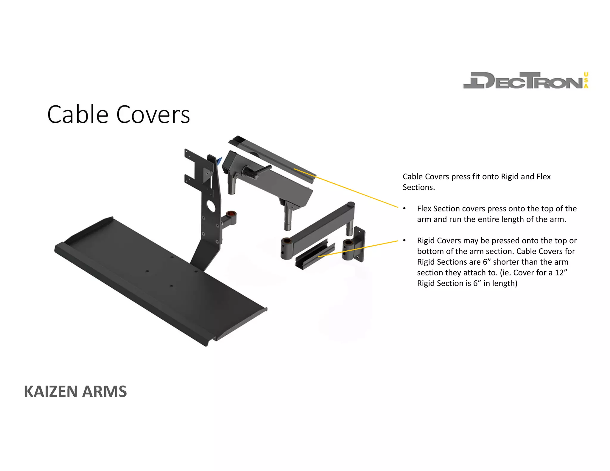
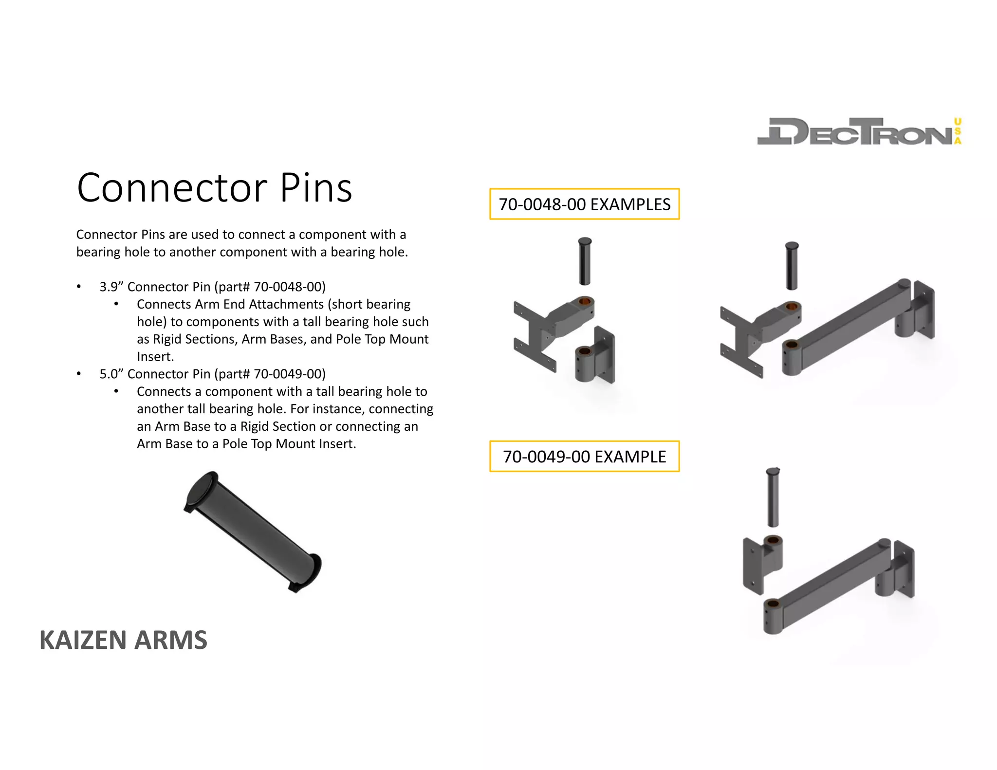
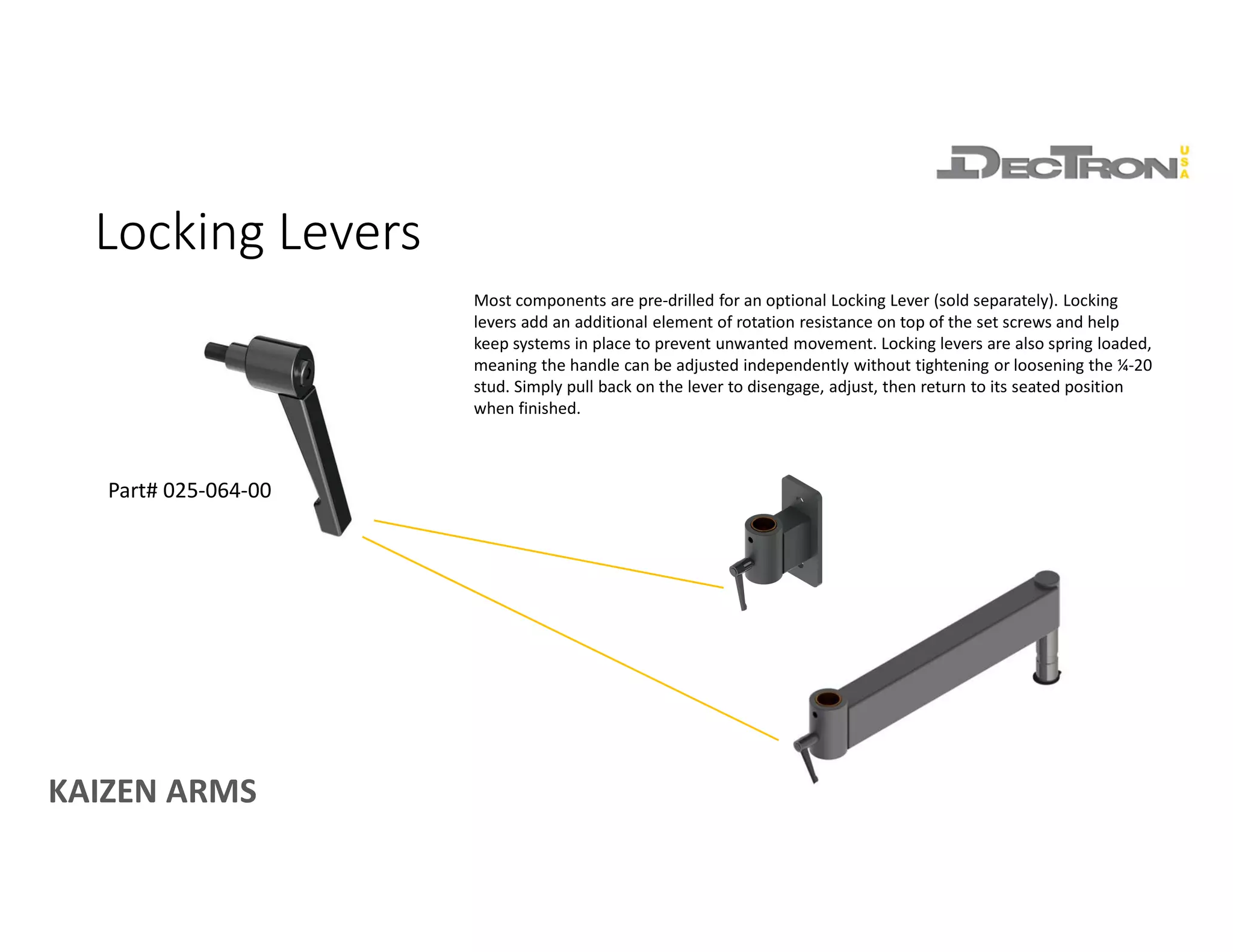
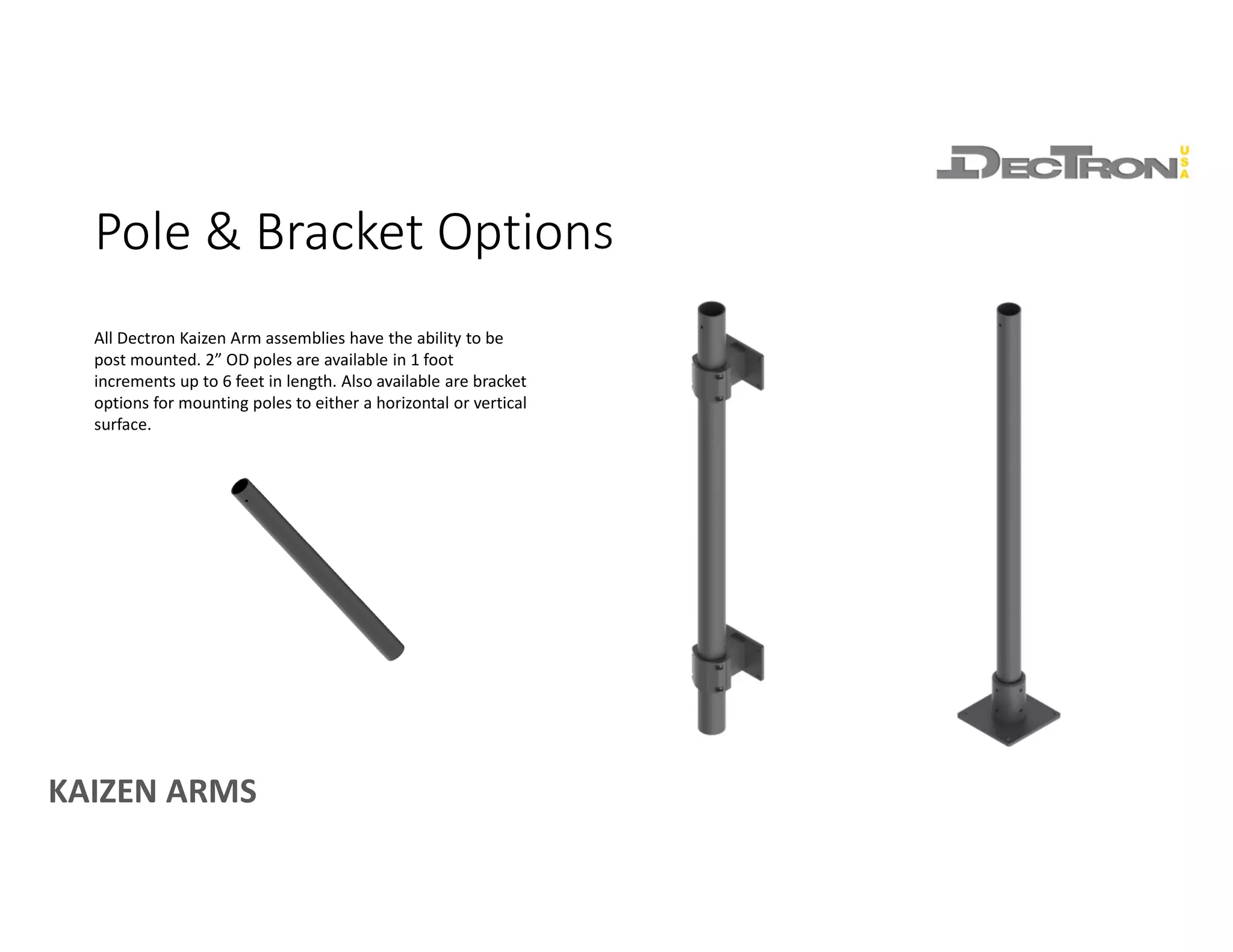
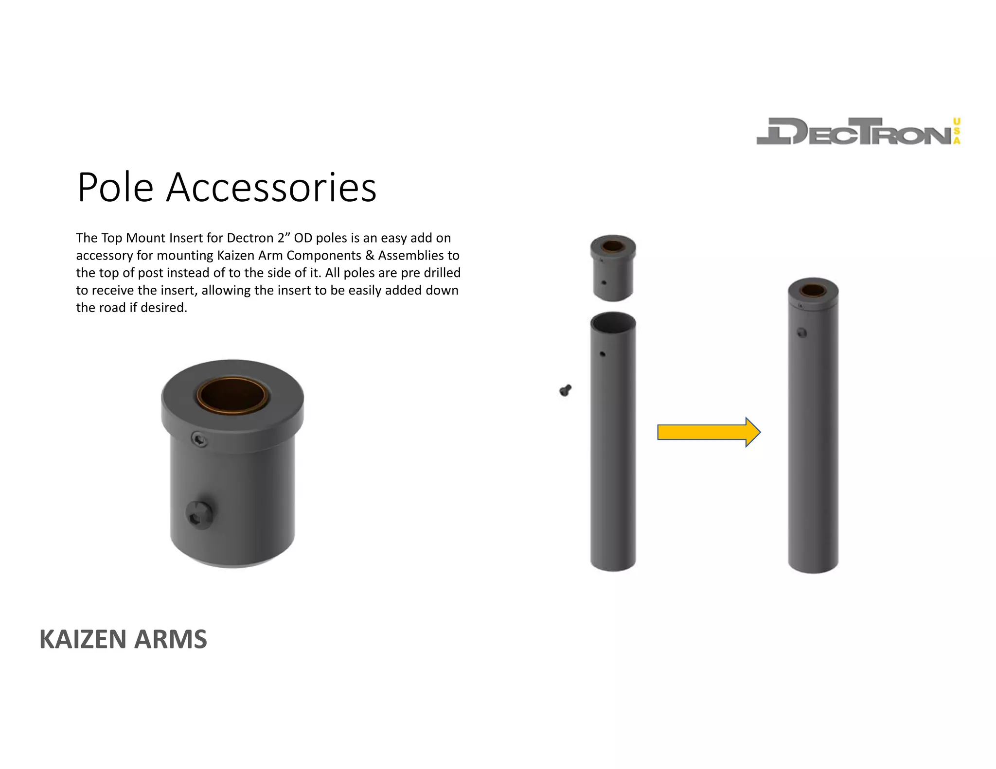
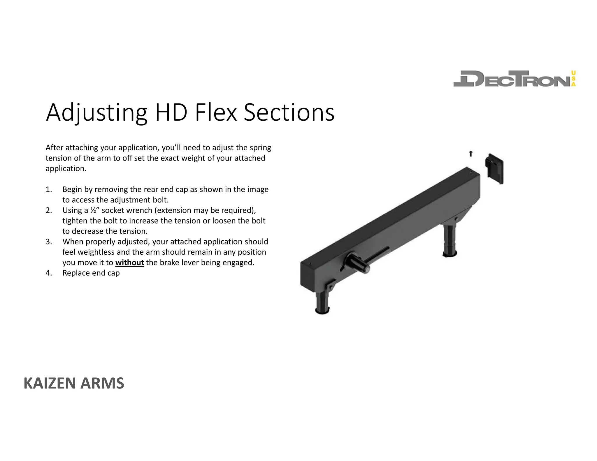
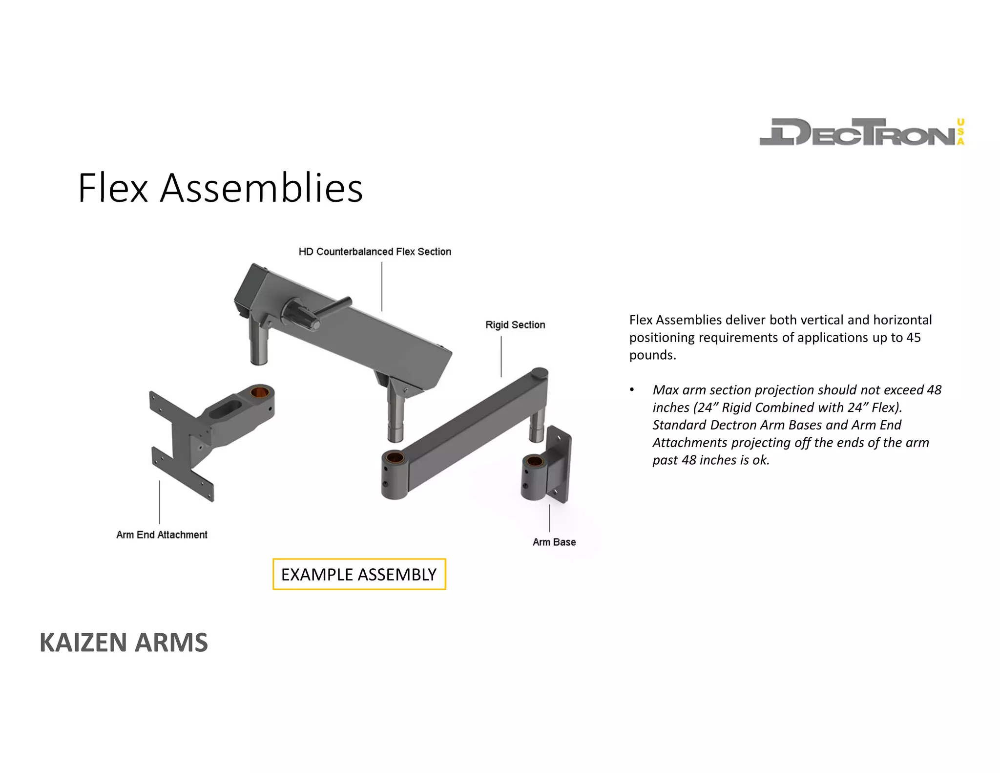
KAIZEN ARMS
An introduction to the components and features of Dectron Kaizen Arms
DECTRON KAIZEN ARMS
MODULAR ERGONOMIC ARMS ENGINEERED FOR INDUSTRY
www.dectronusa.com
KAIZEN ARMS
ARM BASES
KAIZEN ARMS
Arm Bases
A variety of standard Arm Bases are available to
accommodate a wide variety of mounting surfaces including
horizontal surfaces, vertical surfaces and poles. Almost all of
our bases are designed to support arm systems carrying up to
100 pounds at 48 inches of projection.
• All bases feature a set screw for rotation adjustment
• Do not adjust until components are assembled,
doing so will distort the bearing.
• All bases feature a pre-drilled ¼-20 hole for an optional
lever lock (sold separately, part# 025-064-00)
** Not all bases pictured
KAIZEN ARMS
ARM SECTIONS
KAIZEN ARMS
Rigid Sections
Rigid Sections provide extended reach and horizontal
positioning capabilities. Rated for 100 pounds of capacity,
sections can be used alone or linked in any combination up to
48 inches in length while still maintaining a 100 pound load
rating.
• Length Options
• 6”, 12”, 18”, 24”
• Capacity
• 100 pounds
KAIZEN ARMS
HD Flex Sections
HD Flex Sections provide both horizontal and counterbalanced vertical positioning
of attached static loads. When adjusted correctly, attached loads weighing up to 45
pounds will feel weightless as you position them. Additionally, HD Flex Sections
feature a brake lever that may be engaged to prevent vertical arm movement when
interacting with an attached application. This brake lever does not need to be
engaged to keep applications in position.
• Length Options (measurement taken pin center to pin center)
• 13.5”, 18”, 24”
• Capacity
• Up to 45 pounds (capacity varies by model)
KAIZEN ARMS
ARM END ATTACHMENTS
KAIZEN ARMS
Arm End Attachments
A variety of standard Arm End Attachments are offered to
support a range of both standard and custom applications. Arm
End Attachments can be connected to HD Flex Sections or to
Rigid Sections and Arm Bases using the 3.9” Connector Pin
(Part# 70-0048-00).
** Pivot Plate (part# 70-0106-00) only compatible with Rigid Sections.
STANDARD APPLICATIONS
CUSTOM APPLICATIONS
** Not all end attachments pictured
KAIZEN ARMS
CONNECTORS & ACCESSORIES
KAIZEN ARMS
Cable Covers
Cable Covers press fit onto Rigid and Flex
Sections.
• Flex Section covers press onto the top of the
arm and run the entire length of the arm.
• Rigid Covers may be pressed onto the top or
bottom of the arm section. Cable Covers for
Rigid Sections are 6” shorter than the arm
section they attach to. (ie. Cover for a 12”
Rigid Section is 6” in length)
KAIZEN ARMS
Connector Pins
Connector Pins are used to connect a component with a
bearing hole to another component with a bearing hole.
• 3.9” Connector Pin (part# 70-0048-00)
• Connects Arm End Attachments (short bearing
hole) to components with a tall bearing hole such
as Rigid Sections, Arm Bases, and Pole Top Mount
Insert.
• 5.0” Connector Pin (part# 70-0049-00)
• Connects a component with a tall bearing hole to
another tall bearing hole. For instance, connecting
an Arm Base to a Rigid Section or connecting an
Arm Base to a Pole Top Mount Insert.
70-0048-00 EXAMPLES
70-0049-00 EXAMPLE
KAIZEN ARMS
Part# 025-064-00
Most components are pre-drilled for an optional Locking Lever (sold separately). Locking
levers add an additional element of rotation resistance on top of the set screws and help
keep systems in place to prevent unwanted movement. Locking levers are also spring loaded,
meaning the handle can be adjusted independently without tightening or loosening the ¼-20
stud. Simply pull back on the lever to disengage, adjust, then return to its seated position
when finished.
Locking Levers
KAIZEN ARMS
POLES & POLE BRACKETS
KAIZEN ARMS
Pole & Bracket Options
All Dectron Kaizen Arm assemblies have the ability to be
post mounted. 2” OD poles are available in 1 foot
increments up to 6 feet in length. Also available are bracket
options for mounting poles to either a horizontal or vertical
surface.
KAIZEN ARMS
Pole Accessories
The Top Mount Insert for Dectron 2” OD poles is an easy add on
accessory for mounting Kaizen Arm Components & Assemblies to
the top of post instead of to the side of it. All poles are pre drilled
to receive the insert, allowing the insert to be easily added down
the road if desired.
KAIZEN ARMS
SECURING AND ADJUSTING
ASSEMBLIES
KAIZEN ARMS
Securing Assemblies
Securing assemblies is achieved with the included retaining ring. A pair of external
retaining ring pliers designed for use with rings built for a 7/8” shaft are required
but not included. Ensure retaining rings are fully seated in the groove turned into
the arm pin to ensure components are fully secured.
NOTES:
1) Retaining ring not compatible with the HD Table Mount (part# 70-0015-00)
KAIZEN ARMS
Every component that has a bronze bearing hole has a set screw to adjust arm
rotation tension. Arm rotation tension should be adjusted after components are
assembled. Doing so before hand will distort the bearing hole and prevent
components from fitting together correctly.
Adjusting Arm Rotation Tension
KAIZEN ARMS
Adjusting HD Flex Sections
After attaching your application, you’ll need to adjust the spring
tension of the arm to off set the exact weight of your attached
application.
1. Begin by removing the rear end cap as shown in the image
to access the adjustment bolt.
2. Using a ½” socket wrench (extension may be required),
tighten the bolt to increase the tension or loosen the bolt
to decrease the tension.
3. When properly adjusted, your attached application should
feel weightless and the arm should remain in any position
you move it to without the brake lever being engaged.
4. Replace end cap
KAIZEN ARMS
EXAMPLE ARM CONFIGURATIONS
KAIZEN ARMS
Rigid Assemblies
Example Assembly with Rigid Section Used Alone
Example Assembly with Rigid Sections Linked
Rigid Assemblies deliver horizontal positioning of applications weighing up to 100
pounds. Rigid Sections can be linked in any combination up to 48 inches while
maintaining their 100 pound load rating.
• Max arm section projection should not exceed 48 inches (Two 24” Rigid
Sections Linked). Standard Dectron Arm Bases and Arm End Attachments
projecting off the ends of the arm past 48 inches is ok.
KAIZEN ARMS
Flex Assemblies
Flex Assemblies deliver both vertical and horizontal
positioning requirements of applications up to 45
pounds.
• Max arm section projection should not exceed 48
inches (24” Rigid Combined with 24” Flex).
Standard Dectron Arm Bases and Arm End
Attachments projecting off the ends of the arm
past 48 inches is ok.
EXAMPLE ASSEMBLY

Introduction to Dectron Modular Ergonomic Kaizen Arms

  • 1.
    KAIZEN ARMS An introductionto the components and features of Dectron Kaizen Arms DECTRON KAIZEN ARMS MODULAR ERGONOMIC ARMS ENGINEERED FOR INDUSTRY www.dectronusa.com
  • 2.
  • 3.
    KAIZEN ARMS Arm Bases Avariety of standard Arm Bases are available to accommodate a wide variety of mounting surfaces including horizontal surfaces, vertical surfaces and poles. Almost all of our bases are designed to support arm systems carrying up to 100 pounds at 48 inches of projection. • All bases feature a set screw for rotation adjustment • Do not adjust until components are assembled, doing so will distort the bearing. • All bases feature a pre-drilled ¼-20 hole for an optional lever lock (sold separately, part# 025-064-00) ** Not all bases pictured
  • 4.
  • 5.
    KAIZEN ARMS Rigid Sections RigidSections provide extended reach and horizontal positioning capabilities. Rated for 100 pounds of capacity, sections can be used alone or linked in any combination up to 48 inches in length while still maintaining a 100 pound load rating. • Length Options • 6”, 12”, 18”, 24” • Capacity • 100 pounds
  • 6.
    KAIZEN ARMS HD FlexSections HD Flex Sections provide both horizontal and counterbalanced vertical positioning of attached static loads. When adjusted correctly, attached loads weighing up to 45 pounds will feel weightless as you position them. Additionally, HD Flex Sections feature a brake lever that may be engaged to prevent vertical arm movement when interacting with an attached application. This brake lever does not need to be engaged to keep applications in position. • Length Options (measurement taken pin center to pin center) • 13.5”, 18”, 24” • Capacity • Up to 45 pounds (capacity varies by model)
  • 7.
  • 8.
    KAIZEN ARMS Arm EndAttachments A variety of standard Arm End Attachments are offered to support a range of both standard and custom applications. Arm End Attachments can be connected to HD Flex Sections or to Rigid Sections and Arm Bases using the 3.9” Connector Pin (Part# 70-0048-00). ** Pivot Plate (part# 70-0106-00) only compatible with Rigid Sections. STANDARD APPLICATIONS CUSTOM APPLICATIONS ** Not all end attachments pictured
  • 9.
  • 10.
    KAIZEN ARMS Cable Covers CableCovers press fit onto Rigid and Flex Sections. • Flex Section covers press onto the top of the arm and run the entire length of the arm. • Rigid Covers may be pressed onto the top or bottom of the arm section. Cable Covers for Rigid Sections are 6” shorter than the arm section they attach to. (ie. Cover for a 12” Rigid Section is 6” in length)
  • 11.
    KAIZEN ARMS Connector Pins ConnectorPins are used to connect a component with a bearing hole to another component with a bearing hole. • 3.9” Connector Pin (part# 70-0048-00) • Connects Arm End Attachments (short bearing hole) to components with a tall bearing hole such as Rigid Sections, Arm Bases, and Pole Top Mount Insert. • 5.0” Connector Pin (part# 70-0049-00) • Connects a component with a tall bearing hole to another tall bearing hole. For instance, connecting an Arm Base to a Rigid Section or connecting an Arm Base to a Pole Top Mount Insert. 70-0048-00 EXAMPLES 70-0049-00 EXAMPLE
  • 12.
    KAIZEN ARMS Part# 025-064-00 Mostcomponents are pre-drilled for an optional Locking Lever (sold separately). Locking levers add an additional element of rotation resistance on top of the set screws and help keep systems in place to prevent unwanted movement. Locking levers are also spring loaded, meaning the handle can be adjusted independently without tightening or loosening the ¼-20 stud. Simply pull back on the lever to disengage, adjust, then return to its seated position when finished. Locking Levers
  • 13.
    KAIZEN ARMS POLES &POLE BRACKETS
  • 14.
    KAIZEN ARMS Pole &Bracket Options All Dectron Kaizen Arm assemblies have the ability to be post mounted. 2” OD poles are available in 1 foot increments up to 6 feet in length. Also available are bracket options for mounting poles to either a horizontal or vertical surface.
  • 15.
    KAIZEN ARMS Pole Accessories TheTop Mount Insert for Dectron 2” OD poles is an easy add on accessory for mounting Kaizen Arm Components & Assemblies to the top of post instead of to the side of it. All poles are pre drilled to receive the insert, allowing the insert to be easily added down the road if desired.
  • 16.
    KAIZEN ARMS SECURING ANDADJUSTING ASSEMBLIES
  • 17.
    KAIZEN ARMS Securing Assemblies Securingassemblies is achieved with the included retaining ring. A pair of external retaining ring pliers designed for use with rings built for a 7/8” shaft are required but not included. Ensure retaining rings are fully seated in the groove turned into the arm pin to ensure components are fully secured. NOTES: 1) Retaining ring not compatible with the HD Table Mount (part# 70-0015-00)
  • 18.
    KAIZEN ARMS Every componentthat has a bronze bearing hole has a set screw to adjust arm rotation tension. Arm rotation tension should be adjusted after components are assembled. Doing so before hand will distort the bearing hole and prevent components from fitting together correctly. Adjusting Arm Rotation Tension
  • 19.
    KAIZEN ARMS Adjusting HDFlex Sections After attaching your application, you’ll need to adjust the spring tension of the arm to off set the exact weight of your attached application. 1. Begin by removing the rear end cap as shown in the image to access the adjustment bolt. 2. Using a ½” socket wrench (extension may be required), tighten the bolt to increase the tension or loosen the bolt to decrease the tension. 3. When properly adjusted, your attached application should feel weightless and the arm should remain in any position you move it to without the brake lever being engaged. 4. Replace end cap
  • 20.
  • 21.
    KAIZEN ARMS Rigid Assemblies ExampleAssembly with Rigid Section Used Alone Example Assembly with Rigid Sections Linked Rigid Assemblies deliver horizontal positioning of applications weighing up to 100 pounds. Rigid Sections can be linked in any combination up to 48 inches while maintaining their 100 pound load rating. • Max arm section projection should not exceed 48 inches (Two 24” Rigid Sections Linked). Standard Dectron Arm Bases and Arm End Attachments projecting off the ends of the arm past 48 inches is ok.
  • 22.
    KAIZEN ARMS Flex Assemblies FlexAssemblies deliver both vertical and horizontal positioning requirements of applications up to 45 pounds. • Max arm section projection should not exceed 48 inches (24” Rigid Combined with 24” Flex). Standard Dectron Arm Bases and Arm End Attachments projecting off the ends of the arm past 48 inches is ok. EXAMPLE ASSEMBLY