Downloaded 39 times


![Segments and Offsets
Once the starting address is known, the ending
address is found by adding FFFFH.
because a real mode segment of memory is 64K in
length
The offset address is always added to the segment
starting address to locate the data.
[1000:2000H]
a segment address of 1000H; an offset of 2000H](https://image.slidesharecdn.com/internalmicroprocessorarchitecture-150203035614-conversion-gate01/85/Internal-microprocessor-architecture-38-320.jpg)


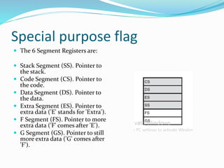
![Default Segment and Offset Registers
The microprocessor has rules that apply to
segments whenever memory is addressed.
These define the segment and offset register
combination
[CS:IP]
The code segment register defines the start of the
code segment.
The instruction pointer locates the next
instruction within the code segment.](https://image.slidesharecdn.com/internalmicroprocessorarchitecture-150203035614-conversion-gate01/85/Internal-microprocessor-architecture-41-320.jpg)


![Default Segment and Offset
Registers
Default segment numbers in:
CS for program (code)
SS for stack
DS for data
ES for string (destination) data
Default offset addresses that go with them
Convention Example: EA = CS:[IP]
Segment Start
in Segment register
Offset: Literal
or in a CPU register](https://image.slidesharecdn.com/internalmicroprocessorarchitecture-150203035614-conversion-gate01/85/Internal-microprocessor-architecture-47-320.jpg)


This document discusses the internal architecture of microprocessors. It begins by listing group members from the University of Gujrat in Pakistan. It then covers several topics regarding microprocessor architecture, including: 1. Internal structures of single-core and dual-core microprocessors. 2. Program visible and invisible programming models and how registers are accessed. 3. Details about general purpose registers like RAX, RBX, RCX, RDX and segment registers. 4. Special purpose registers including flags, instruction pointer, and stack pointer.


![[ASM] Lab2](https://cdn.slidesharecdn.com/ss_thumbnails/asmlab2-161012104901-thumbnail.jpg?width=640&height=640&fit=bounds)