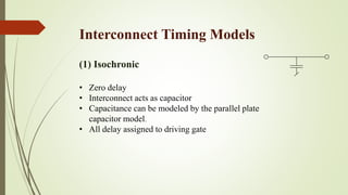
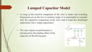
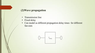
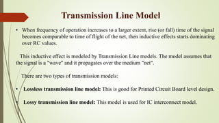
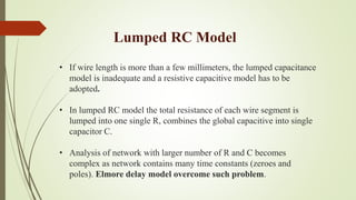
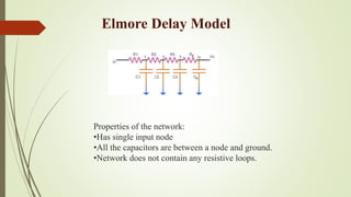
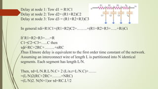
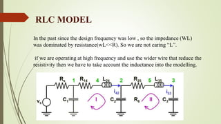
INTERCONNECT TIMING MODEL
PRACHI PANDEY
(16215004)
Interconnect Delay
Interconnect delay is the difference between the time a signal is first applied
to the net and the time it reaches other devices connected to that net.
It is due to the finite resistance and capacitance of the net. It is also known as
wire delay.
Wire delay = function of (Rnet, Cnet+Cpin)
This is output pin of the cell to the input pin of the next cell.
Net delay is calculated using Rs and Cs
Interconnect introduces capacitive, resistive and inductive parasites.
All three have multiple effects on the circuit behavior.
1.Interconnect parasites cause an increase in propagation delay (i.e.
it slows down working speed)
2.Interconnect parasites increase energy dissipation and affect the
power distribution.
3.Interconnect parasites introduce extra noise sources, which affect
reliability of the circuit.
Interconnect Timing Models
(1) Isochronic
• Zero delay
• Interconnect acts as capacitor
• Capacitance can be modeled by the parallel plate
capacitor model.
• All delay assigned to driving gate
Lumped Capacitor Model
• As long as the resistive component of the wire is small, and switching
frequencies are in the low to medium range, it is meaningful to consider
only the capacitive component of the wire, and to lump the distributed
capacitance into a single capacitance.
• The only impact on performance is
introduced by the loading effect of the
capacitor on the driving gate
(2)Wave propagation
• Transmission line
• Fixed delay
• Can model as different propagation delay times for different
fan-outs
Tdelay
Transmission Line Model
• When frequency of operation increases to a larger extent, rise (or fall) time of the signal
becomes comparable to time of flight of the net, then inductive effects starts dominating
over RC values.
This inductive effect is modeled by Transmission Line models. The model assumes that
the signal is a "wave" and it propagates over the medium "net".
There are two types of transmission models:
• Lossless transmission line model: This is good for Printed Circuit Board level design.
• Lossy transmission line model: This model is used for IC interconnect model.
Lumped RC Model
• If wire length is more than a few millimeters, the lumped capacitance
model is inadequate and a resistive capacitive model has to be
adopted.
• In lumped RC model the total resistance of each wire segment is
lumped into one single R, combines the global capacitive into single
capacitor C.
• Analysis of network with larger number of R and C becomes
complex as network contains many time constants (zeroes and
poles). Elmore delay model overcome such problem.
Elmore Delay Model
Properties of the network:
•Has single input node
•All the capacitors are between a node and ground.
•Network does not contain any resistive loops.
Delay at node 1: Tow d1 = R1C1
Delay at node 2: Tow d2= (R1+R2)C2
Delay at node 3: Tow d3 = (R1+R2+R3)C3
In general:τdi=R1C1+(R1+R2)C2+……..+(R1+R2+R3+…..+Ri)Ci
If R1=R2=R3=….=R
C1=C2=C3=…..C then
τdi=RC+2RC+……..+nRC
Thus Elmore delay is equivalent to the first order time constant of the network.
Assuming an interconnect wire of length L is partitioned into N identical
segments. Each segment has length L/N.
Then, τd=L/N.R.L/N.C+ 2 (L/n.r+L/N.C)+……
=(L/N)2(RC+2RC+…….+NRC)
=(L/N)2. N(N+1)or τd=RC.L2/2
Distributed RC model
• Lumped RC model is always pessimistic and distributed RC model
provides better accuracy over lumped RC model.
• But distributed RC model is complex and no closed form solution
exists. Hence distributed RC line model is not suitable for
Computer Aided Design Tools.
• The behavior of the distributed RC line can be approximated by a
lumped RC ladder network such as Elmore Delay model hence
these are used in EDA tools.
(3)Signal diffusion
• Distributed RLC parasitics
• Inertial delay
• combine with driver timing model
RLC MODEL
In the past since the design frequency was low , so the impedance (WL)
was dominated by resistance(wL<<R). So we are not caring “L”.
if we are operating at high frequency and use the wider wire that reduce the
resistivity then we have to take account the inductance into the modelling.
References
• http://asic-soc.blogspot.in/2008/10/net-delay.html
• Jan M. Rabaey, Anantha Chandrakasan and Borivoje Nikolic,
"Digital Integrated Circuits- A Design Perspective", Prentice Hall,
Second Edition
• http://www.ee.iitm.ac.in/~ee09d017/interconnect_problems_in_vlsi.
pdf
• http://www.vlsi-expert.com/2011/09/delay-interconnect-delay-
models-static.html
THANK YOU

Interconnect timing model

  • 1.
  • 2.
    Interconnect Delay Interconnect delayis the difference between the time a signal is first applied to the net and the time it reaches other devices connected to that net. It is due to the finite resistance and capacitance of the net. It is also known as wire delay. Wire delay = function of (Rnet, Cnet+Cpin) This is output pin of the cell to the input pin of the next cell. Net delay is calculated using Rs and Cs
  • 3.
    Interconnect introduces capacitive,resistive and inductive parasites. All three have multiple effects on the circuit behavior. 1.Interconnect parasites cause an increase in propagation delay (i.e. it slows down working speed) 2.Interconnect parasites increase energy dissipation and affect the power distribution. 3.Interconnect parasites introduce extra noise sources, which affect reliability of the circuit.
  • 4.
    Interconnect Timing Models (1)Isochronic • Zero delay • Interconnect acts as capacitor • Capacitance can be modeled by the parallel plate capacitor model. • All delay assigned to driving gate
  • 5.
    Lumped Capacitor Model •As long as the resistive component of the wire is small, and switching frequencies are in the low to medium range, it is meaningful to consider only the capacitive component of the wire, and to lump the distributed capacitance into a single capacitance. • The only impact on performance is introduced by the loading effect of the capacitor on the driving gate
  • 6.
    (2)Wave propagation • Transmissionline • Fixed delay • Can model as different propagation delay times for different fan-outs Tdelay
  • 7.
    Transmission Line Model •When frequency of operation increases to a larger extent, rise (or fall) time of the signal becomes comparable to time of flight of the net, then inductive effects starts dominating over RC values. This inductive effect is modeled by Transmission Line models. The model assumes that the signal is a "wave" and it propagates over the medium "net". There are two types of transmission models: • Lossless transmission line model: This is good for Printed Circuit Board level design. • Lossy transmission line model: This model is used for IC interconnect model.
  • 8.
    Lumped RC Model •If wire length is more than a few millimeters, the lumped capacitance model is inadequate and a resistive capacitive model has to be adopted. • In lumped RC model the total resistance of each wire segment is lumped into one single R, combines the global capacitive into single capacitor C. • Analysis of network with larger number of R and C becomes complex as network contains many time constants (zeroes and poles). Elmore delay model overcome such problem.
  • 9.
    Elmore Delay Model Propertiesof the network: •Has single input node •All the capacitors are between a node and ground. •Network does not contain any resistive loops.
  • 10.
    Delay at node1: Tow d1 = R1C1 Delay at node 2: Tow d2= (R1+R2)C2 Delay at node 3: Tow d3 = (R1+R2+R3)C3 In general:τdi=R1C1+(R1+R2)C2+……..+(R1+R2+R3+…..+Ri)Ci If R1=R2=R3=….=R C1=C2=C3=…..C then τdi=RC+2RC+……..+nRC Thus Elmore delay is equivalent to the first order time constant of the network. Assuming an interconnect wire of length L is partitioned into N identical segments. Each segment has length L/N. Then, τd=L/N.R.L/N.C+ 2 (L/n.r+L/N.C)+…… =(L/N)2(RC+2RC+…….+NRC) =(L/N)2. N(N+1)or τd=RC.L2/2
  • 11.
    Distributed RC model •Lumped RC model is always pessimistic and distributed RC model provides better accuracy over lumped RC model. • But distributed RC model is complex and no closed form solution exists. Hence distributed RC line model is not suitable for Computer Aided Design Tools. • The behavior of the distributed RC line can be approximated by a lumped RC ladder network such as Elmore Delay model hence these are used in EDA tools.
  • 12.
    (3)Signal diffusion • DistributedRLC parasitics • Inertial delay • combine with driver timing model
  • 13.
    RLC MODEL In thepast since the design frequency was low , so the impedance (WL) was dominated by resistance(wL<<R). So we are not caring “L”. if we are operating at high frequency and use the wider wire that reduce the resistivity then we have to take account the inductance into the modelling.
  • 14.
    References • http://asic-soc.blogspot.in/2008/10/net-delay.html • JanM. Rabaey, Anantha Chandrakasan and Borivoje Nikolic, "Digital Integrated Circuits- A Design Perspective", Prentice Hall, Second Edition • http://www.ee.iitm.ac.in/~ee09d017/interconnect_problems_in_vlsi. pdf • http://www.vlsi-expert.com/2011/09/delay-interconnect-delay- models-static.html
  • 15.