Download to read offline

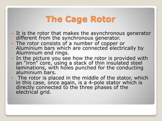
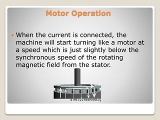


The document discusses induction generators, also known as asynchronous generators, which are commonly used in wind turbines. It describes how induction generators were originally designed as electric motors but can also function as generators. When the rotor spins faster than the rotating magnetic field in the stator, it induces strong currents in the rotor that are converted to electricity. Induction generators have some advantages for wind turbines, like being reliable and inexpensive. They also allow the turbine speed to vary slightly with changes in torque load.


