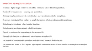
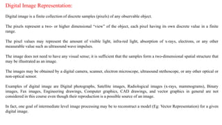
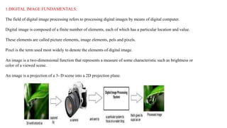
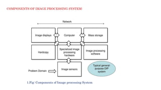
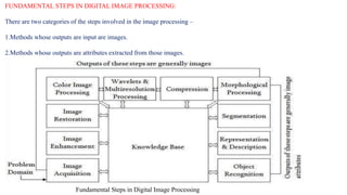
The document provides a comprehensive overview of digital image processing, covering concepts such as image sampling, sensors, and the various applications in fields like remote sensing, medical imaging, and robotics. It details the components of an image processing system, including hardware and software requirements, along with essential steps in image processing like acquisition, enhancement, and recognition. Key aspects such as digital image representation, quantization, and the importance of spatial and gray level resolution are also discussed.


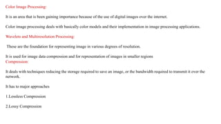
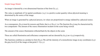
![L min ≤ l ≤ Lmax Lminis to be positive and Lmax must be finite
Lmin =iminrmin
Lmax =imaxrmax
The interval [Lmin, Lmax] is called gray scale.
Common practice is to shift this interval numerically to the interval [0, L-l]
where l=0 is considered black and
l= L-1 is considered white on the gray scale.
All intermediate values are shades of gray of gray varying from black to white.](https://image.slidesharecdn.com/imageprocessingfundamentals-240502121003-d6e054d5/85/Image-Processing-Fundamentals-ppt-20-320.jpg)