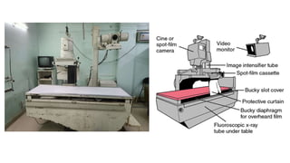
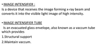
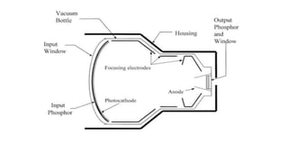
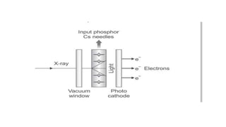
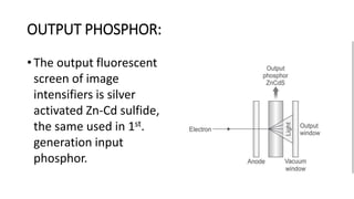
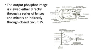
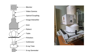
IMAGE INTENSIFIER
DR.GAJANAN WATTAMWAR
JR 1 RADIODIAGNOSIS
•IMAGE INTENSIFIER :
Is a device that receives the image forming x-ray beam and
converts it into the visible light image of high intensity.
•IMAGE INTENSIFIER TUBE
Is an evacuated glass envelope, also known as a vaccum tube
which provides
1.Structural support
2.Maintain vaccum.
IMAGE INTENSIFIER
HISTORY
 Image intensifier was discovered in 1950s
In intension to produce an image bright enough to allow cone
vision.
It helped in investigation without giving the patient an excess
radiation exposure.
THE COMPONENTS OF AN X-RAY IMAGE INTENSIFIER
•The tube itself is an evacuated envelope vacuum tube with:
1. Input phosphor and photocathode .
2. Electrostatic focusing lens.
3. Accelerating anode.
4. Output phosphor.
• After an x-ray beam passes the patient it enters the
image intensifier tube
• The input fluorescent screen absorbs x-ray photons
and converts their energy into light photons.
• The light photons strike the photo cathode, causing it
to emit photoelectrons
• These electrons are immediately drawn away from the
photocathode by the high potential difference
between it & the accelerating anode.
• As the electrons flow from the cathode towards the
anode, they are focused by an electrostatic lens which
guides them to the output fluorescent screen without
distorting their geometric configuration.
• The electrons strike the output screen, which emits
the light photons that carry the fluoroscopic images to
the eye of the observer.
• In intensifier tube, the image is first carried by the x-
ray photons, then by the light photons, next by the
electrons &finally by the light photons.
INPUT PHOSPHOR & PHOTO CATHODE:
• The Input fluorescent screen in image intensifiers is
cesium iodide (CsI). (older intensifier- silver activated
zinc cadmium sulfide).
• A useful characteristic of CsI is that during the
deposition process the crystals of CsI grow in tiny
needles perpendicular to the substrate thereby
reducing scattering.
INPUT PHOSPHOR & PHOTO CATHODE:
• Image quality is better with CsI input
screen than it was with zinc cadmium sulfide screens.
• Two physical characteristics of CsI make it superior.
1. Vertical orientation of the crystals.
2. A greater packing density.
PHOTO CATHODE:
• The photo cathode is a photoemissive metal
(commonly a combination of antimony & cesium
compounds).
• When the light from the fluorescent screen strikes
the photo cathode, photo electrons are emitted.
• The photo cathode is applied directly to the CsI input
phosphor.
• The photoelectrons thus produced has to be moved
to the other end of the image intensifier.
• This can be done by using an electrostatic focusing
lens and an accelerating anode.
ELECTROSTATIC FOCUSING LENS:
•The lens is made up of a series positively charged electrodes
that are usually plated on to the inside surface of the glass
envelope to focus the beam towards output phosphor.
•Electron focusing inverts & reverses the image which is called
“point inversion” because all the electrons pass through a
common focal point on their way to output phosphor.
• The input phosphor is curved to ensure that electrons
emitted at the peripheral regions of the photocathode
travel the same distance as those emitted from the
central region.
• The image on the output phosphor is reduced in size,
which is one of the principle reasons why it is brighter.
ACCELERATING ANODE :
• The anode is located in the neck of the image tube.
• Its function is to accelerate electrons emitted from the
photocathode towards the output screen.
• The anode has a +ve potential of 25 to 35 kv relative
to the photocathode, so it accelerates electrons to a
tremendous velocity.
OUTPUT PHOSPHOR:
• The output fluorescent
screen of image
intensifiers is silver
activated Zn-Cd sulfide,
the same used in 1st.
generation input
phosphor.
• A thin layer of aluminum is plated onto the
fluorescent screen, prevent light from moving
retrograde through the tube & activating the
photocathode.
• The glass tube of the image intensifier is about 2 to
4mm thick &is enclosed in a lead lined metal
container--- protects the operator from stray
radiation.
•The output phosphor image
is viewed either directly
through a series of lenses
and mirrors or indirectly
through closed circuit TV.
GAIN:
• The extent to which image intensifier has intensified
the light emitted from the output screen in
comparison with that from the input screen.
• Ratio of the brightness of the output phosphor to that
of the input phosphor.
• 2 factors are responsible :
1. Flux gain
2. Minification gain
FLUX GAIN:
• A single light photon produced in the input phosphor
causes a single electron to be emitted from the
photocathode.
• Following acceleration to about 25 keV by the
focusing field in the intensifier, each electron causes
many light photons to be emitted from the output
phosphor.
MINIFICATION GAIN :
• The intensification caused by reducing the image size
from the input to output screen.
• Ratio of the square of the areas of the two screens.
• BRIGHTNESS GAIN = Flux gain X Minification gain.
Imaging characteristics:
•Contrast:
Contrast is the brightness ratio of the periphery to
the center of the output screen.
Two factors diminish the contrast in image intensifiers:
1. The input screen does not absorb all the photons in the
xray beam. Some are transmitted through the intensifier
tube and few are even actually absorbed by the output
screen.
2. Retrograde light flow from the output screen. They
produce a background fog which reduces the contrast.
Lag:
• Lag is defined as persistence of luminescence after
xray stimulation has been terminated.
• Older tubes lag time: 30-40 ms
• CsI tubes : 1 ms.
Distortion:
•The electric fields that accurately control electrons in the
center of the image are not capable for the same degree
of control for the peripheral electrons.
•Peripheral electrons do not strike the output phosphor
where they ideally should and thus tend to flare out from
an ideal course.
• The result is an unequal magnification which produces
peripheral distortion.
• Hence center of an image intensifier has a better
resolution, brighter image and less geometric
distortion.
Geometrical Distortion :
•Geometrical distortion is made up of pincushion distortion
and S-type distortion
Pincushion Distortion :
•Pincushion distortion is due to curved geometry of the input
screen.
• The effect of magnetic fields on the electron path causes the
S-type distortion.
• But, both of the distortions are not visible and less significant
during fluoroscopy imaging.
Closed circuit television system
• Used to view the image intensifier output image.
• Consists of :
1. Television camera
2. Optical coupling.
3. Monitor
The television system allows for real time viewing of the
fluoroscopic image by several people at once.
•The output phosphor is directly coupled to the TV camera
tube.
•The basic components of video camera consists of :
1. Vacuum tube cylinder, surrounded by electromagnetic
focusing coils and 2 pairs of electrostatic deflecting coils.
2. Photoconductive target.
3. Scanning electron beam.
Image Intensifier and Camera Coupling
• The optical system connects the Image intensifier tube
and camera, so that there is no loss of light.
• There are two ways of optical coupling, namely,
1.Lens system
2. Fiberoptic system.
1.LENS SYSTEM:
•The lens system is a traditional method, bigger in size,
suitable for cine or photospot camera.
•The objective lens receives the light from the output
phosphor and converts into a parallel beam.
•Whenever image is recorded on film, the mirror split the
beam, and sends a part of a beam to the video camera. The
remaining portion will be sent to the film camera.
•This will enable to view images during recording
2. FIBEROPTIC SYSTEM.
• It is a simplest method with bundle of fiberoptics,
which is few mm thick and contains 1000 of glass
fibers per square mm.
• It is easy to move the Image intensifier tube with the
fibreoptic system .
Television monitor
•The video signal produced by the video camera is
converted into a visible image by the monitor.
•Contains picture tube and controls for regulating
contrast and brightness.
LIMITATIONS OF IMAGE INTENSIFIER SYSTEMS
1.The unit is large in size, difficult to position during the
procedure.
2. If there is air leak in the Image intensifier tube, the
vacuum is destroyed, resulting in degraded image quality.
3. If the voltage of the electrodes is not correctly adjusted,
the electrons will not reach the focal point (defocusing
effect). It may result in blurred image .
AUTOMATIC BRIGHTNESS CONTROL
• In fluoroscopy imaging, if image intensifier moves
from a thinner to thicker region of the patient, higher
the amount of attenuation of X-rays. This will reduce
the brightness of the output screen.
• Automatic brightness control (ABC) is a mechanism,
which can keep the brightness of the image constant
at the monitor.
• It is basically a feedback circuit, which measures the
light intensity of the output screen or video camera
signal.
• ABC regulate the X-ray exposure rate incident on the
input phosphor of the Image intensifier tube, by
changing the kV or mA automatically.
• In general, the brightness of the central area of the
output screen is taken into account for adjustment.
• Brightness can be adjusted by both kV and mA, which
has influence on contrast and patient dose,
respectively.
AUTOMATIC GAIN CONTROL
• Alternatively, the brightness of the image on the
monitor can be adjusted by varying the gain of the TV
system, which is called automatic gain control (AGC).
• This will result in unwanted radiation dose. Generally,
mA is adjusted as a first step to obtain the input dose
rate of Image intensifier tube.
• If the current limit is reached, then kV is adjusted to
get the input dose rate.
• Even it is not sufficient then, AGC option is used to
adjust the video display brightness.
Summary:
•Image intensifiers discovered in 1950s alleviated this
problem by producing a image bright enough to be viewed
by cone vision.
•BRIGHTNESS GAIN = Flux gain X Minification gain.
•Important imaging characteristics : contrast, lag and
distortion
•Output phosphor image is processed by television camera
tube.
•The image is displayed on TV monitor.
THANK YOU
REFERENCES :
•Christensen’s Physics of Diagnostic Radiology – 4th
edition.
• The fundamentals of imaging and physics and
radiobiology –Joseph Selman 9th edition
• The AAPM/RSNA Physics Tutorial for Residents X-ray
Image Intensifiers for Fluoroscopy 2000 Sept-Oct
•The AAPM/RSNA Physics Tutorial for Residents
Fluoroscopy: Recording of Fluoroscopic Images and
Automatic Exposure Control. 2000 Jan-Feb

image intensifier.pptx

  • 1.
  • 3.
    •IMAGE INTENSIFIER : Isa device that receives the image forming x-ray beam and converts it into the visible light image of high intensity. •IMAGE INTENSIFIER TUBE Is an evacuated glass envelope, also known as a vaccum tube which provides 1.Structural support 2.Maintain vaccum.
  • 4.
    IMAGE INTENSIFIER HISTORY  Imageintensifier was discovered in 1950s In intension to produce an image bright enough to allow cone vision. It helped in investigation without giving the patient an excess radiation exposure.
  • 5.
    THE COMPONENTS OFAN X-RAY IMAGE INTENSIFIER •The tube itself is an evacuated envelope vacuum tube with: 1. Input phosphor and photocathode . 2. Electrostatic focusing lens. 3. Accelerating anode. 4. Output phosphor.
  • 7.
    • After anx-ray beam passes the patient it enters the image intensifier tube • The input fluorescent screen absorbs x-ray photons and converts their energy into light photons. • The light photons strike the photo cathode, causing it to emit photoelectrons
  • 8.
    • These electronsare immediately drawn away from the photocathode by the high potential difference between it & the accelerating anode. • As the electrons flow from the cathode towards the anode, they are focused by an electrostatic lens which guides them to the output fluorescent screen without distorting their geometric configuration.
  • 10.
    • The electronsstrike the output screen, which emits the light photons that carry the fluoroscopic images to the eye of the observer. • In intensifier tube, the image is first carried by the x- ray photons, then by the light photons, next by the electrons &finally by the light photons.
  • 11.
    INPUT PHOSPHOR &PHOTO CATHODE: • The Input fluorescent screen in image intensifiers is cesium iodide (CsI). (older intensifier- silver activated zinc cadmium sulfide). • A useful characteristic of CsI is that during the deposition process the crystals of CsI grow in tiny needles perpendicular to the substrate thereby reducing scattering.
  • 13.
    INPUT PHOSPHOR &PHOTO CATHODE: • Image quality is better with CsI input screen than it was with zinc cadmium sulfide screens. • Two physical characteristics of CsI make it superior. 1. Vertical orientation of the crystals. 2. A greater packing density.
  • 14.
    PHOTO CATHODE: • Thephoto cathode is a photoemissive metal (commonly a combination of antimony & cesium compounds). • When the light from the fluorescent screen strikes the photo cathode, photo electrons are emitted.
  • 15.
    • The photocathode is applied directly to the CsI input phosphor. • The photoelectrons thus produced has to be moved to the other end of the image intensifier. • This can be done by using an electrostatic focusing lens and an accelerating anode.
  • 16.
    ELECTROSTATIC FOCUSING LENS: •Thelens is made up of a series positively charged electrodes that are usually plated on to the inside surface of the glass envelope to focus the beam towards output phosphor. •Electron focusing inverts & reverses the image which is called “point inversion” because all the electrons pass through a common focal point on their way to output phosphor.
  • 17.
    • The inputphosphor is curved to ensure that electrons emitted at the peripheral regions of the photocathode travel the same distance as those emitted from the central region. • The image on the output phosphor is reduced in size, which is one of the principle reasons why it is brighter.
  • 18.
    ACCELERATING ANODE : •The anode is located in the neck of the image tube. • Its function is to accelerate electrons emitted from the photocathode towards the output screen. • The anode has a +ve potential of 25 to 35 kv relative to the photocathode, so it accelerates electrons to a tremendous velocity.
  • 19.
    OUTPUT PHOSPHOR: • Theoutput fluorescent screen of image intensifiers is silver activated Zn-Cd sulfide, the same used in 1st. generation input phosphor.
  • 20.
    • A thinlayer of aluminum is plated onto the fluorescent screen, prevent light from moving retrograde through the tube & activating the photocathode. • The glass tube of the image intensifier is about 2 to 4mm thick &is enclosed in a lead lined metal container--- protects the operator from stray radiation.
  • 21.
    •The output phosphorimage is viewed either directly through a series of lenses and mirrors or indirectly through closed circuit TV.
  • 22.
    GAIN: • The extentto which image intensifier has intensified the light emitted from the output screen in comparison with that from the input screen. • Ratio of the brightness of the output phosphor to that of the input phosphor. • 2 factors are responsible : 1. Flux gain 2. Minification gain
  • 23.
    FLUX GAIN: • Asingle light photon produced in the input phosphor causes a single electron to be emitted from the photocathode. • Following acceleration to about 25 keV by the focusing field in the intensifier, each electron causes many light photons to be emitted from the output phosphor.
  • 24.
    MINIFICATION GAIN : •The intensification caused by reducing the image size from the input to output screen. • Ratio of the square of the areas of the two screens. • BRIGHTNESS GAIN = Flux gain X Minification gain.
  • 25.
    Imaging characteristics: •Contrast: Contrast isthe brightness ratio of the periphery to the center of the output screen.
  • 26.
    Two factors diminishthe contrast in image intensifiers: 1. The input screen does not absorb all the photons in the xray beam. Some are transmitted through the intensifier tube and few are even actually absorbed by the output screen. 2. Retrograde light flow from the output screen. They produce a background fog which reduces the contrast.
  • 27.
    Lag: • Lag isdefined as persistence of luminescence after xray stimulation has been terminated. • Older tubes lag time: 30-40 ms • CsI tubes : 1 ms.
  • 28.
    Distortion: •The electric fieldsthat accurately control electrons in the center of the image are not capable for the same degree of control for the peripheral electrons. •Peripheral electrons do not strike the output phosphor where they ideally should and thus tend to flare out from an ideal course.
  • 29.
    • The resultis an unequal magnification which produces peripheral distortion. • Hence center of an image intensifier has a better resolution, brighter image and less geometric distortion.
  • 30.
    Geometrical Distortion : •Geometricaldistortion is made up of pincushion distortion and S-type distortion Pincushion Distortion : •Pincushion distortion is due to curved geometry of the input screen. • The effect of magnetic fields on the electron path causes the S-type distortion. • But, both of the distortions are not visible and less significant during fluoroscopy imaging.
  • 32.
    Closed circuit televisionsystem • Used to view the image intensifier output image. • Consists of : 1. Television camera 2. Optical coupling. 3. Monitor The television system allows for real time viewing of the fluoroscopic image by several people at once.
  • 33.
    •The output phosphoris directly coupled to the TV camera tube. •The basic components of video camera consists of : 1. Vacuum tube cylinder, surrounded by electromagnetic focusing coils and 2 pairs of electrostatic deflecting coils. 2. Photoconductive target. 3. Scanning electron beam.
  • 35.
    Image Intensifier andCamera Coupling • The optical system connects the Image intensifier tube and camera, so that there is no loss of light. • There are two ways of optical coupling, namely, 1.Lens system 2. Fiberoptic system.
  • 36.
    1.LENS SYSTEM: •The lenssystem is a traditional method, bigger in size, suitable for cine or photospot camera. •The objective lens receives the light from the output phosphor and converts into a parallel beam. •Whenever image is recorded on film, the mirror split the beam, and sends a part of a beam to the video camera. The remaining portion will be sent to the film camera. •This will enable to view images during recording
  • 38.
    2. FIBEROPTIC SYSTEM. •It is a simplest method with bundle of fiberoptics, which is few mm thick and contains 1000 of glass fibers per square mm. • It is easy to move the Image intensifier tube with the fibreoptic system .
  • 39.
    Television monitor •The videosignal produced by the video camera is converted into a visible image by the monitor. •Contains picture tube and controls for regulating contrast and brightness.
  • 40.
    LIMITATIONS OF IMAGEINTENSIFIER SYSTEMS 1.The unit is large in size, difficult to position during the procedure. 2. If there is air leak in the Image intensifier tube, the vacuum is destroyed, resulting in degraded image quality. 3. If the voltage of the electrodes is not correctly adjusted, the electrons will not reach the focal point (defocusing effect). It may result in blurred image .
  • 41.
    AUTOMATIC BRIGHTNESS CONTROL •In fluoroscopy imaging, if image intensifier moves from a thinner to thicker region of the patient, higher the amount of attenuation of X-rays. This will reduce the brightness of the output screen. • Automatic brightness control (ABC) is a mechanism, which can keep the brightness of the image constant at the monitor.
  • 42.
    • It isbasically a feedback circuit, which measures the light intensity of the output screen or video camera signal. • ABC regulate the X-ray exposure rate incident on the input phosphor of the Image intensifier tube, by changing the kV or mA automatically.
  • 43.
    • In general,the brightness of the central area of the output screen is taken into account for adjustment. • Brightness can be adjusted by both kV and mA, which has influence on contrast and patient dose, respectively.
  • 44.
    AUTOMATIC GAIN CONTROL •Alternatively, the brightness of the image on the monitor can be adjusted by varying the gain of the TV system, which is called automatic gain control (AGC). • This will result in unwanted radiation dose. Generally, mA is adjusted as a first step to obtain the input dose rate of Image intensifier tube.
  • 45.
    • If thecurrent limit is reached, then kV is adjusted to get the input dose rate. • Even it is not sufficient then, AGC option is used to adjust the video display brightness.
  • 47.
    Summary: •Image intensifiers discoveredin 1950s alleviated this problem by producing a image bright enough to be viewed by cone vision. •BRIGHTNESS GAIN = Flux gain X Minification gain. •Important imaging characteristics : contrast, lag and distortion •Output phosphor image is processed by television camera tube. •The image is displayed on TV monitor.
  • 48.
  • 49.
    REFERENCES : •Christensen’s Physicsof Diagnostic Radiology – 4th edition. • The fundamentals of imaging and physics and radiobiology –Joseph Selman 9th edition • The AAPM/RSNA Physics Tutorial for Residents X-ray Image Intensifiers for Fluoroscopy 2000 Sept-Oct •The AAPM/RSNA Physics Tutorial for Residents Fluoroscopy: Recording of Fluoroscopic Images and Automatic Exposure Control. 2000 Jan-Feb

Editor's Notes

  • #25 Brightness gain called as intensification factor Modern days II reach upto the values of 10,000 to 20,000 Conversion factor( Ratio of luminance of output phosphor to input exposure rate) is 1% of brightness gain so, a conversion factor of 100 is actually 10,000 which is actually used In specification