Downloaded 314 times
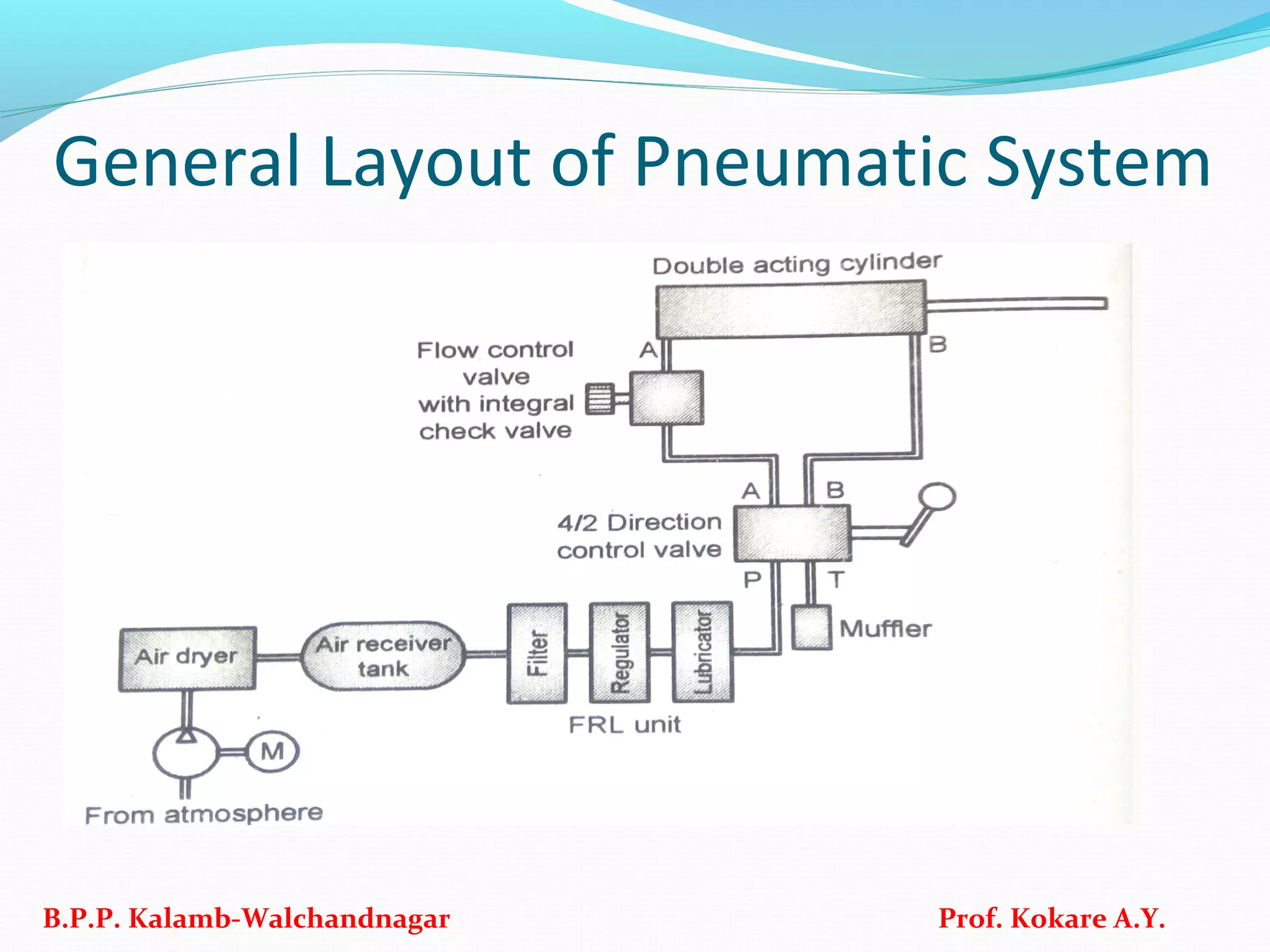
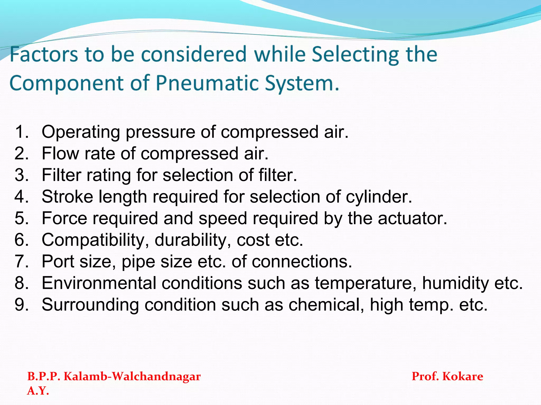
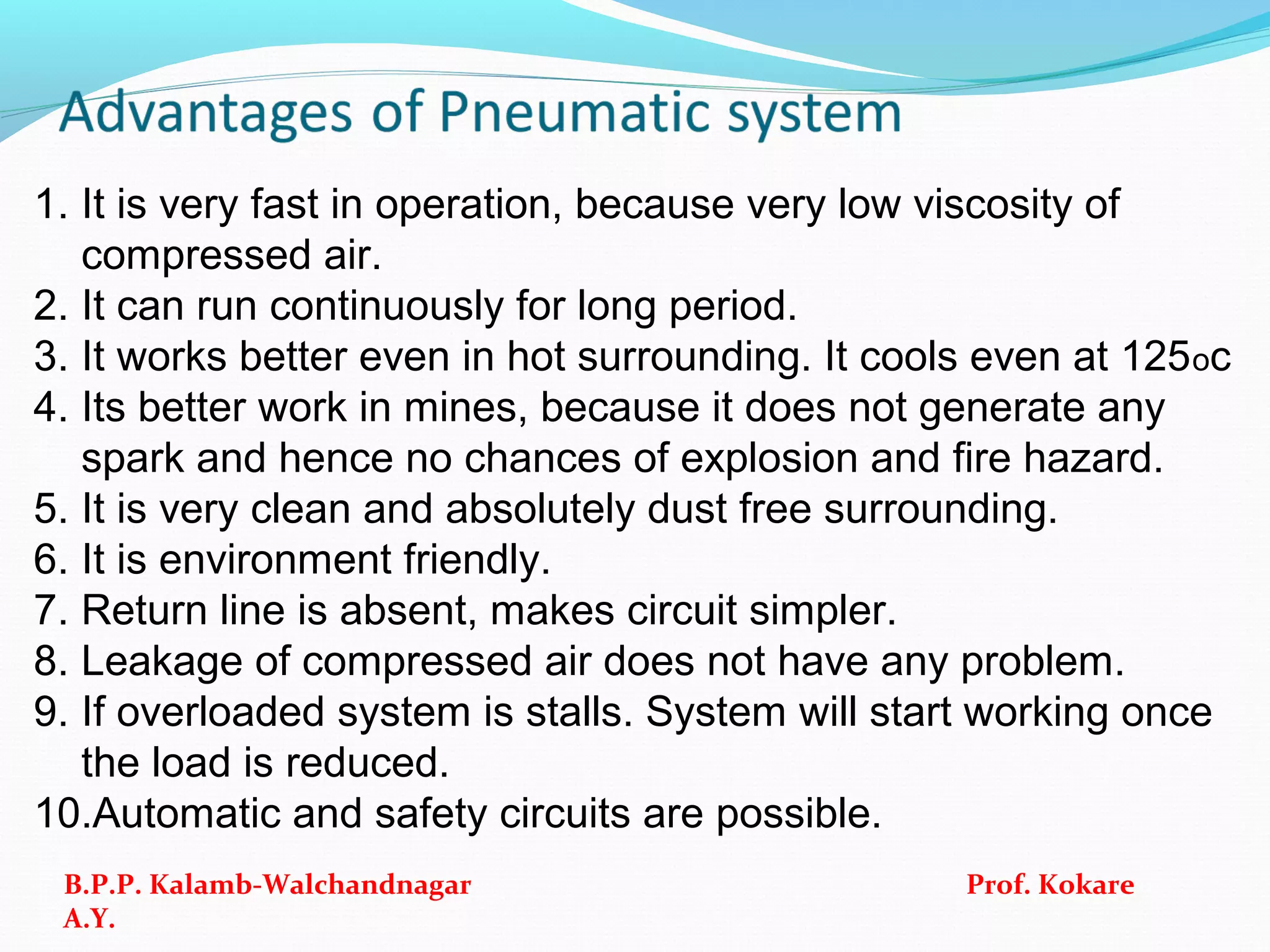
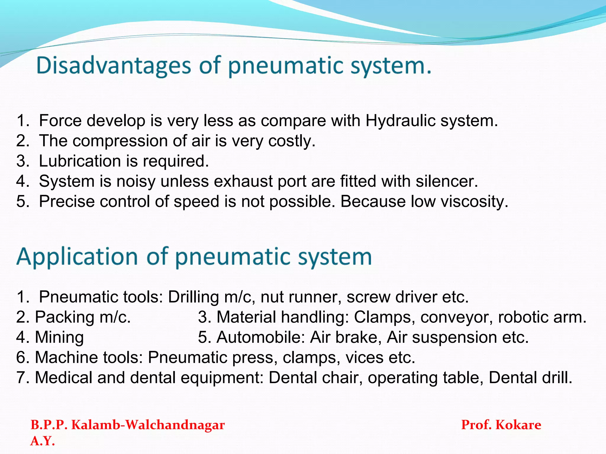
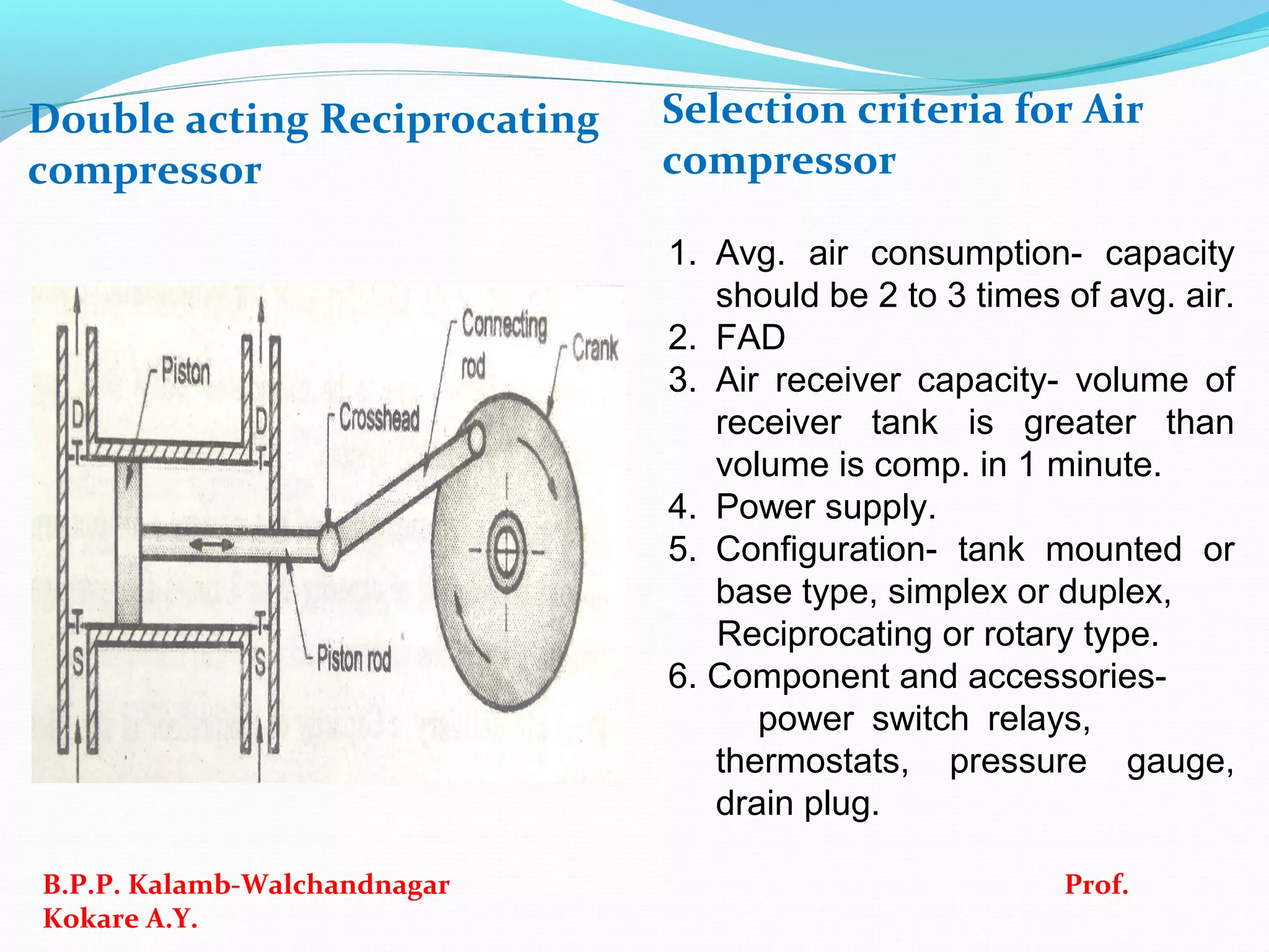
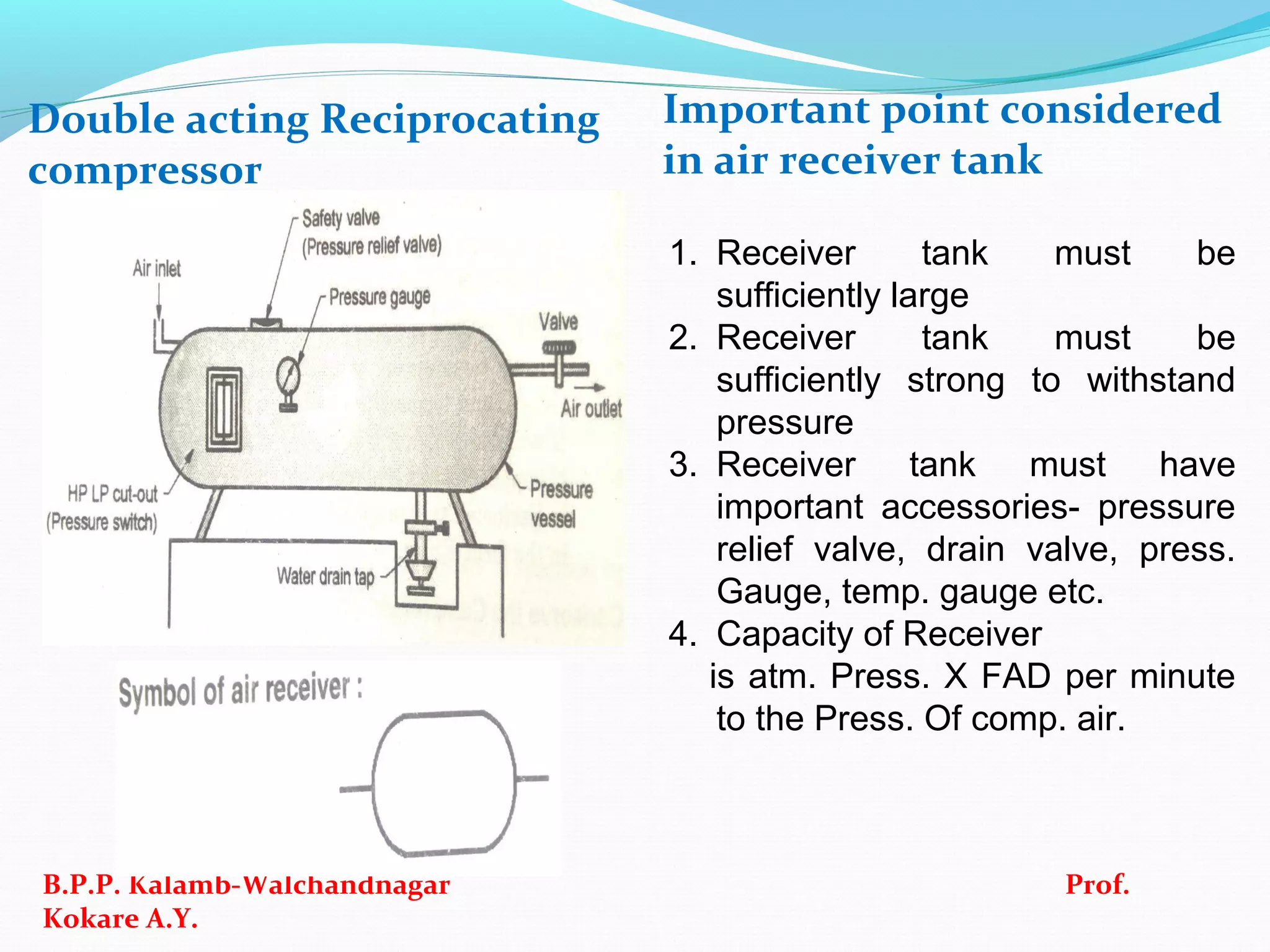
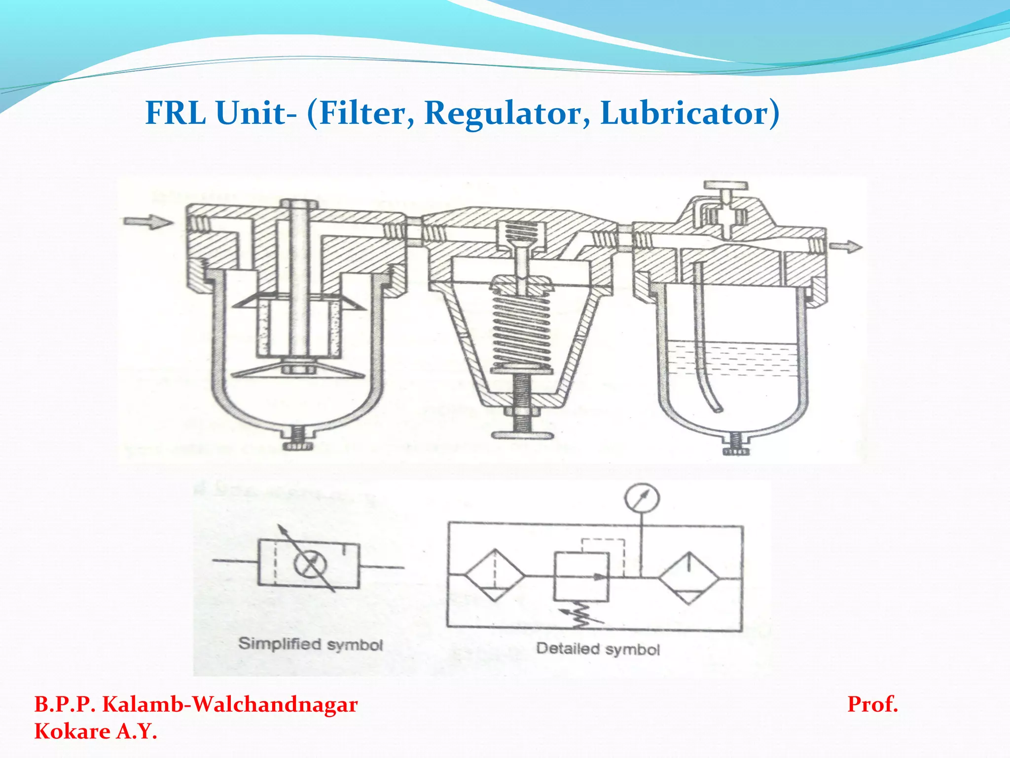
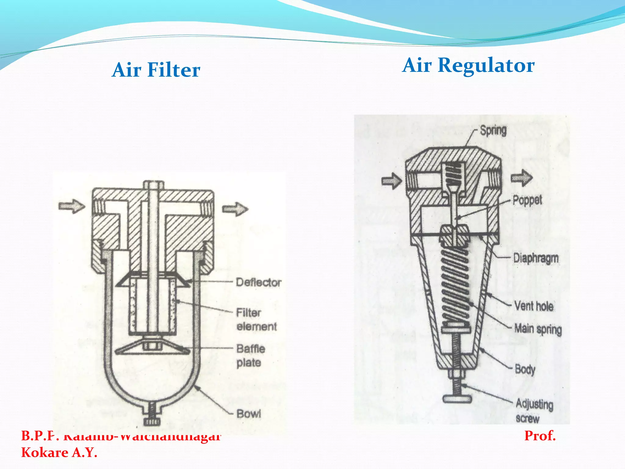
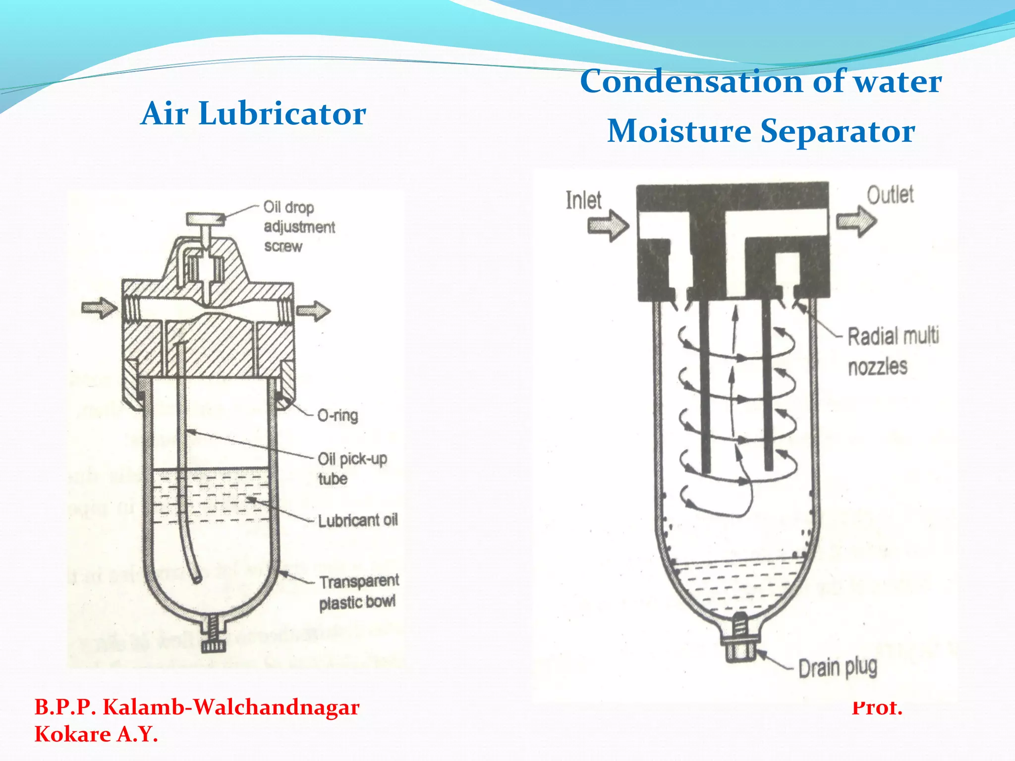
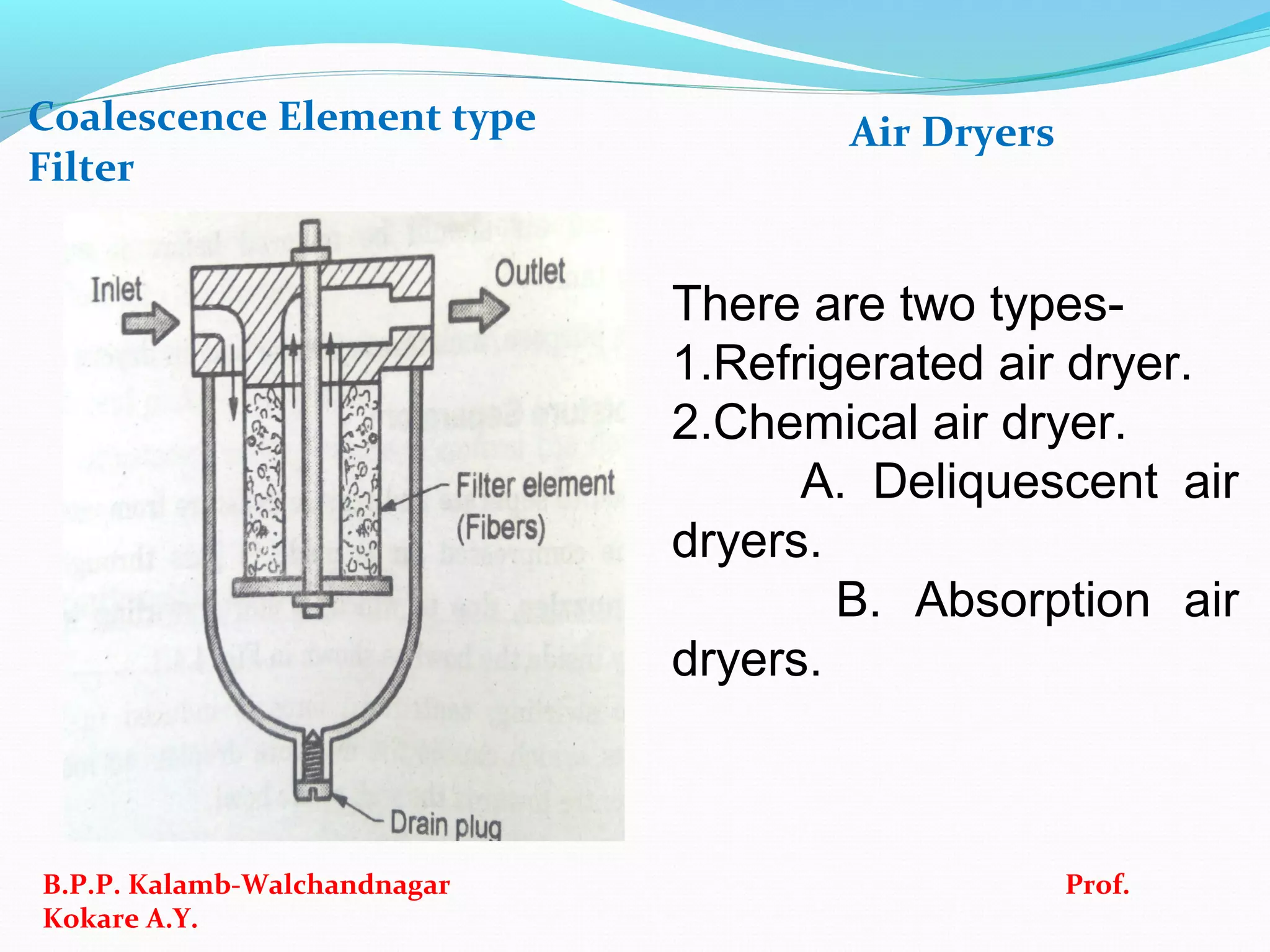
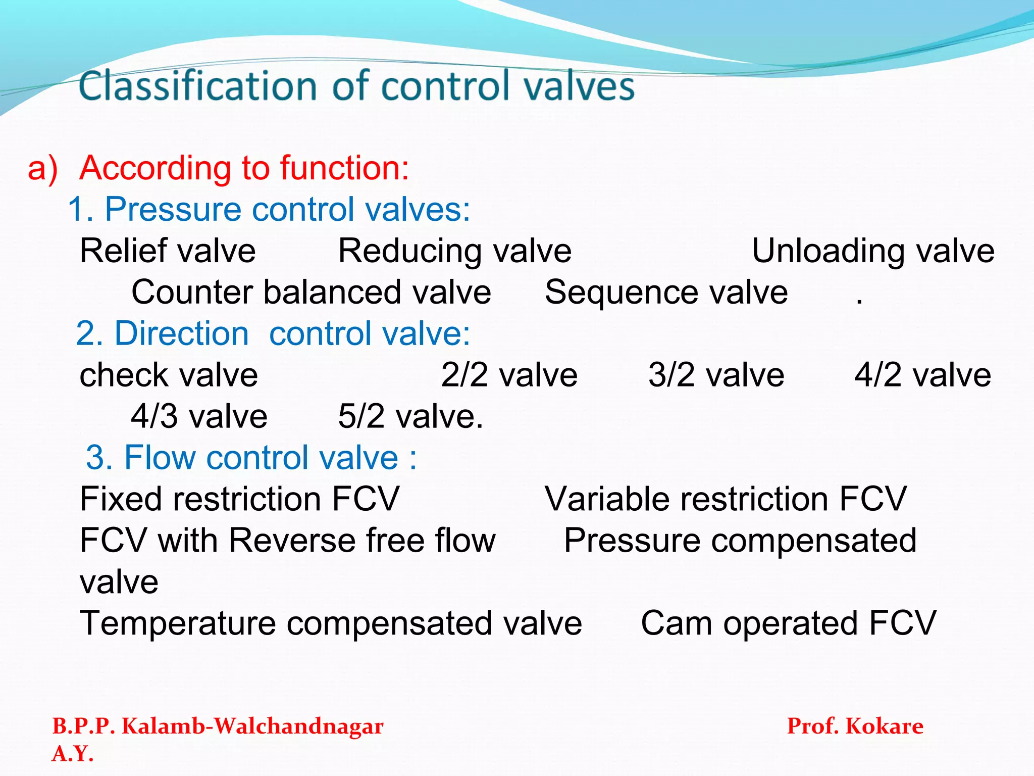


The document covers the fundamentals of pneumatic systems, focusing on components, operating principles, and benefits such as speed and safety in hazardous environments. It includes criteria for selecting compressors and receiver tanks, types of valves, and applications in various fields like mining and medical equipment. Additionally, it discusses seal types and reasons for their failure in hydraulic systems.


