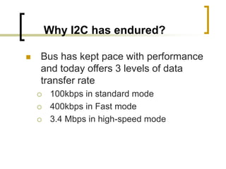
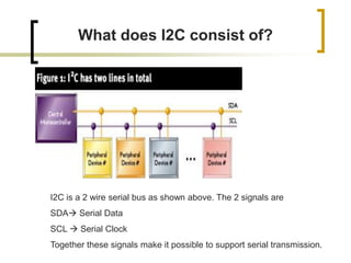
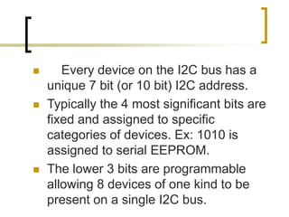
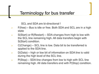
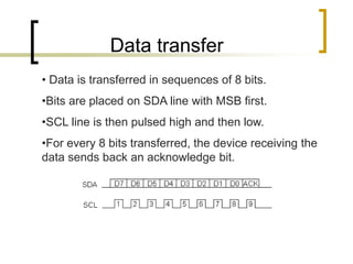
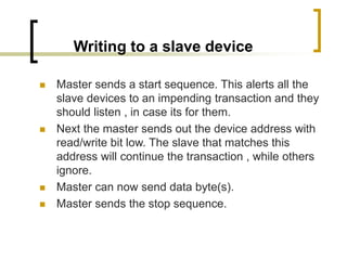
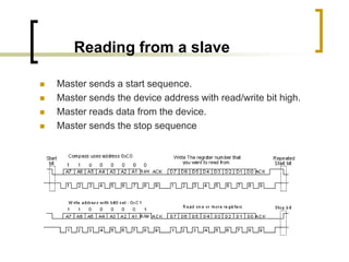
I2C
(Inter-IC bus)
By
Tejaswini Gadicherla
(tgadiche@uncc.edu)
Topics Discussed….
 What is I2C ???
 Why has it endured?
 Bus transfer terminology
 How does it work?
Introduction to I2C
 I2C is a control bus providing
communications link between integrated
circuits in a system.
 Developed by Philips in the early 1980s.
 Examples of I2C-compatible devices
found in embedded systems include
EEPROMs, thermal sensors and real-time
clock.
Why I2C has endured?
 Bus has kept pace with performance
and today offers 3 levels of data
transfer rate
 100kbps in standard mode
 400kbps in Fast mode
 3.4 Mbps in high-speed mode
Why I2C has endured?
 Reliable performance using software-
controlled collision detection and
arbitration.
 Ease of use. 2 lines connect all ICs in
a system.
 Software controlled addressing
scheme eliminating need for address-
decoding hardware.
What does I2C consist of?
I2C is a 2 wire serial bus as shown above. The 2 signals are
SDA Serial Data
SCL  Serial Clock
Together these signals make it possible to support serial transmission.
I2C BUS
 The device that initiates the transaction on the I2C
bus is termed the master. The master normally
controls the clock signal.
 A device being addressed by the master is called
the slave.
 There needs to be at least one master( a
microcontroller or a DSP) on the bus, but there can
be more than one master. All the masters on a bus
have equal priority.
 Every device on the I2C bus has a
unique 7 bit (or 10 bit) I2C address.
 Typically the 4 most significant bits are
fixed and assigned to specific
categories of devices. Ex: 1010 is
assigned to serial EEPROM.
 The lower 3 bits are programmable
allowing 8 devices of one kind to be
present on a single I2C bus.
Terminology for bus transfer
SCL and SDA are bi-directional !
 F(free) – Bus is idle or free. Both SDA and SCL are in a high
state
 S(Start) or R(Restart) – SDA changes from high to low with
the SCL line remaining high. All data transfers begin with
S(Start) condition.
 C(Change) – SCL line is low. Data bit to be transferred is
applied to the SDA line.
 D(Data) – high or low bit of information on SDA line is valid
during the high level of the SCL line.
 P(Stop) – SDA line changes from low to high with SCL line
remaining high. All data transfers end with P(Stop) condition.
Data transfer
• Data is transferred in sequences of 8 bits.
•Bits are placed on SDA line with MSB first.
•SCL line is then pulsed high and then low.
•For every 8 bits transferred, the device receiving the
data sends back an acknowledge bit.
Data transfer(contd)
 If the receiving device sends back an low ACK bit,
then it has received the data and is ready to accept
another byte.
 If it sends back a high ACK, then the device is
indicating that it cannot accept any further data and
the master should terminate the transfer by sending
a stop sequence.
Writing to a slave device
 Master sends a start sequence. This alerts all the
slave devices to an impending transaction and they
should listen , in case its for them.
 Next the master sends out the device address with
read/write bit low. The slave that matches this
address will continue the transaction , while others
ignore.
 Master can now send data byte(s).
 Master sends the stop sequence.
Reading from a slave
 Master sends a start sequence.
 Master sends the device address with read/write bit high.
 Master reads data from the device.
 Master sends the stop sequence
References
 http://www.semiconductors.philips.com/m
arkets/mms/protocols/i2c/facts/
 http://www.embedded.com/story/OEG200
10718S0073
 http://www.mcc-us.com/i2chowto.htm

I2C PRESENTATION.PPT

  • 1.
  • 2.
    Topics Discussed….  Whatis I2C ???  Why has it endured?  Bus transfer terminology  How does it work?
  • 3.
    Introduction to I2C I2C is a control bus providing communications link between integrated circuits in a system.  Developed by Philips in the early 1980s.  Examples of I2C-compatible devices found in embedded systems include EEPROMs, thermal sensors and real-time clock.
  • 4.
    Why I2C hasendured?  Bus has kept pace with performance and today offers 3 levels of data transfer rate  100kbps in standard mode  400kbps in Fast mode  3.4 Mbps in high-speed mode
  • 5.
    Why I2C hasendured?  Reliable performance using software- controlled collision detection and arbitration.  Ease of use. 2 lines connect all ICs in a system.  Software controlled addressing scheme eliminating need for address- decoding hardware.
  • 6.
    What does I2Cconsist of? I2C is a 2 wire serial bus as shown above. The 2 signals are SDA Serial Data SCL  Serial Clock Together these signals make it possible to support serial transmission.
  • 7.
    I2C BUS  Thedevice that initiates the transaction on the I2C bus is termed the master. The master normally controls the clock signal.  A device being addressed by the master is called the slave.  There needs to be at least one master( a microcontroller or a DSP) on the bus, but there can be more than one master. All the masters on a bus have equal priority.
  • 8.
     Every deviceon the I2C bus has a unique 7 bit (or 10 bit) I2C address.  Typically the 4 most significant bits are fixed and assigned to specific categories of devices. Ex: 1010 is assigned to serial EEPROM.  The lower 3 bits are programmable allowing 8 devices of one kind to be present on a single I2C bus.
  • 9.
    Terminology for bustransfer SCL and SDA are bi-directional !  F(free) – Bus is idle or free. Both SDA and SCL are in a high state  S(Start) or R(Restart) – SDA changes from high to low with the SCL line remaining high. All data transfers begin with S(Start) condition.  C(Change) – SCL line is low. Data bit to be transferred is applied to the SDA line.  D(Data) – high or low bit of information on SDA line is valid during the high level of the SCL line.  P(Stop) – SDA line changes from low to high with SCL line remaining high. All data transfers end with P(Stop) condition.
  • 10.
    Data transfer • Datais transferred in sequences of 8 bits. •Bits are placed on SDA line with MSB first. •SCL line is then pulsed high and then low. •For every 8 bits transferred, the device receiving the data sends back an acknowledge bit.
  • 11.
    Data transfer(contd)  Ifthe receiving device sends back an low ACK bit, then it has received the data and is ready to accept another byte.  If it sends back a high ACK, then the device is indicating that it cannot accept any further data and the master should terminate the transfer by sending a stop sequence.
  • 12.
    Writing to aslave device  Master sends a start sequence. This alerts all the slave devices to an impending transaction and they should listen , in case its for them.  Next the master sends out the device address with read/write bit low. The slave that matches this address will continue the transaction , while others ignore.  Master can now send data byte(s).  Master sends the stop sequence.
  • 13.
    Reading from aslave  Master sends a start sequence.  Master sends the device address with read/write bit high.  Master reads data from the device.  Master sends the stop sequence
  • 14.