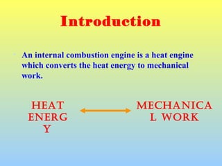
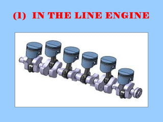
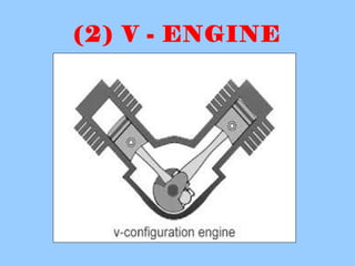
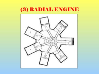
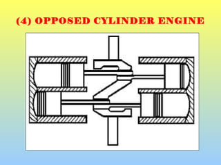
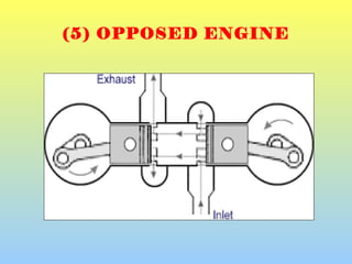
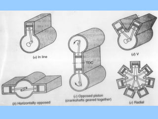
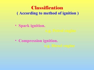
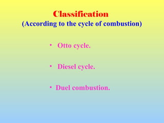
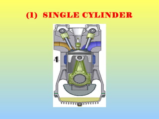
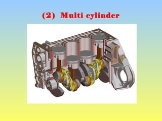
1) The document discusses different types of internal combustion engines including their classification based on cylinder arrangement, ignition method, combustion cycle, cooling method, and number of cylinders.
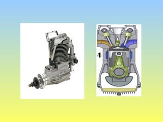
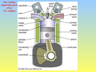
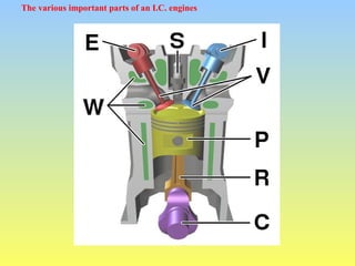
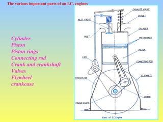
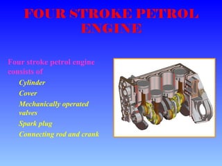
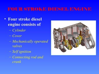
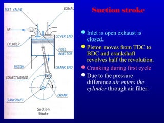
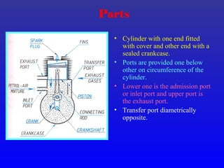
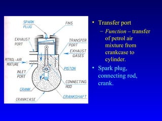
2) The key parts of an internal combustion engine are described including the cylinder, piston, piston rings, connecting rod, crank and crankshaft, valves, flywheel, and crankcase.
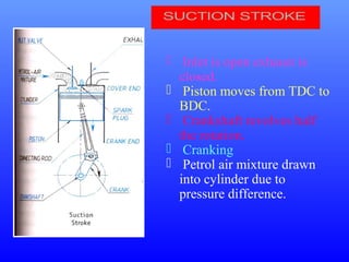
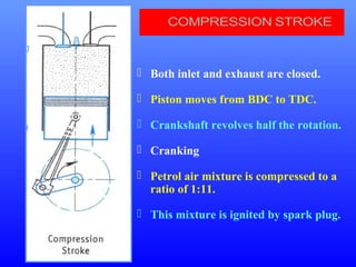
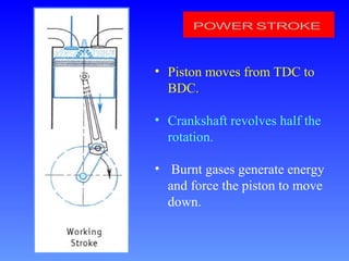
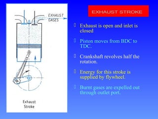
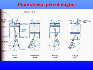
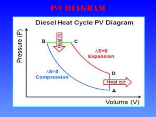
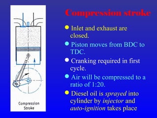
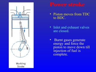
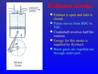
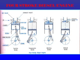
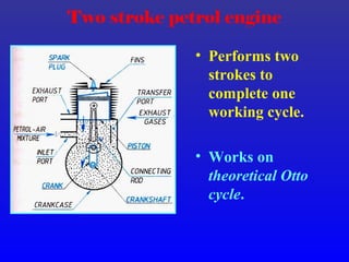
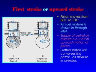
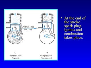
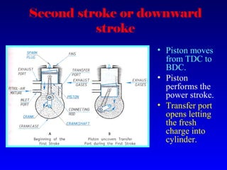
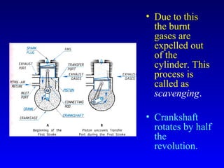
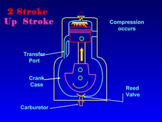
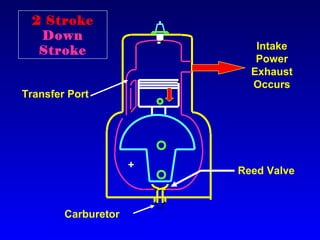
3) The four stroke cycles of both petrol and diesel engines are explained as intake, compression, power, and exhaust strokes along with the corresponding piston movement and crankshaft rotation in each stroke.