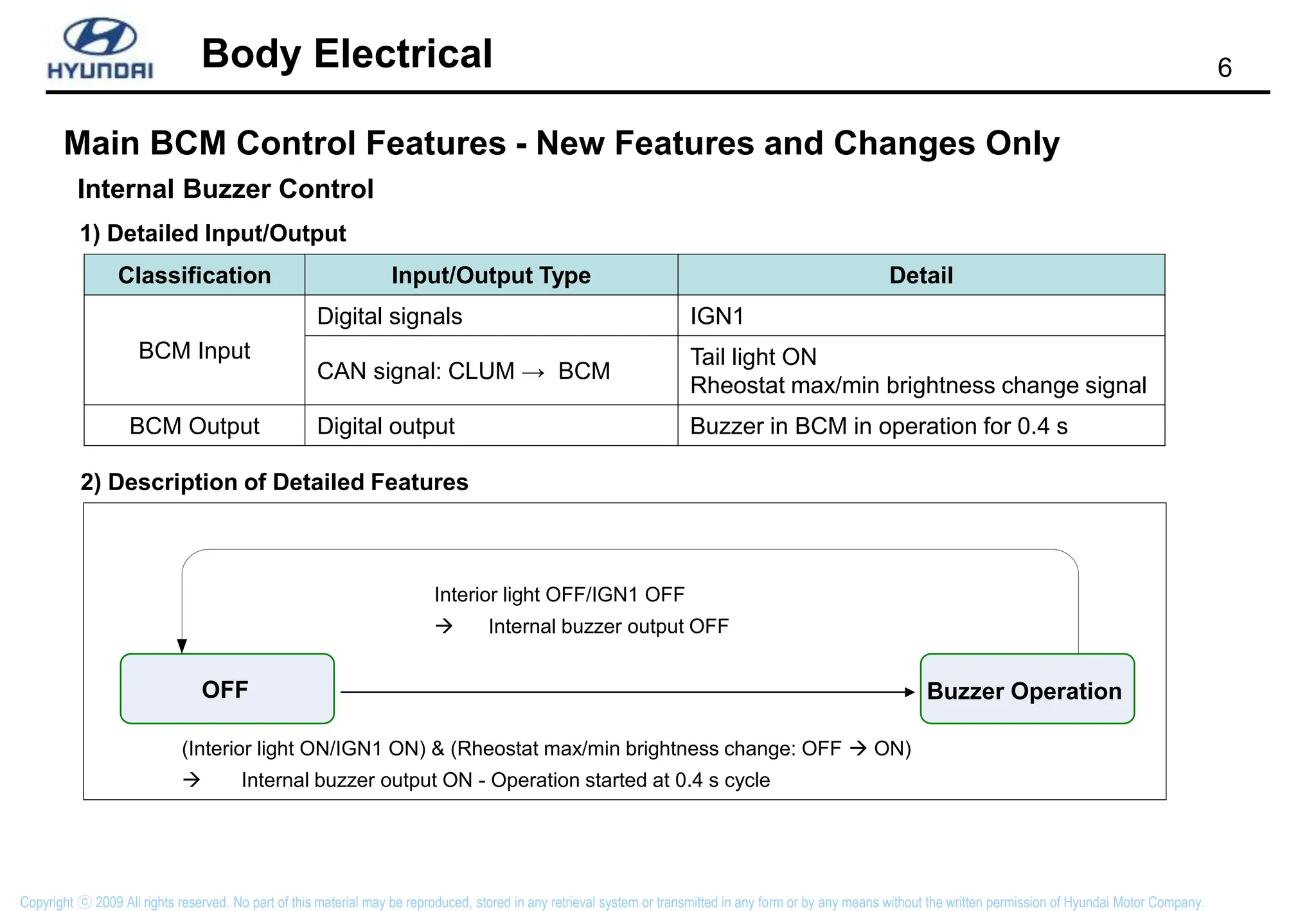
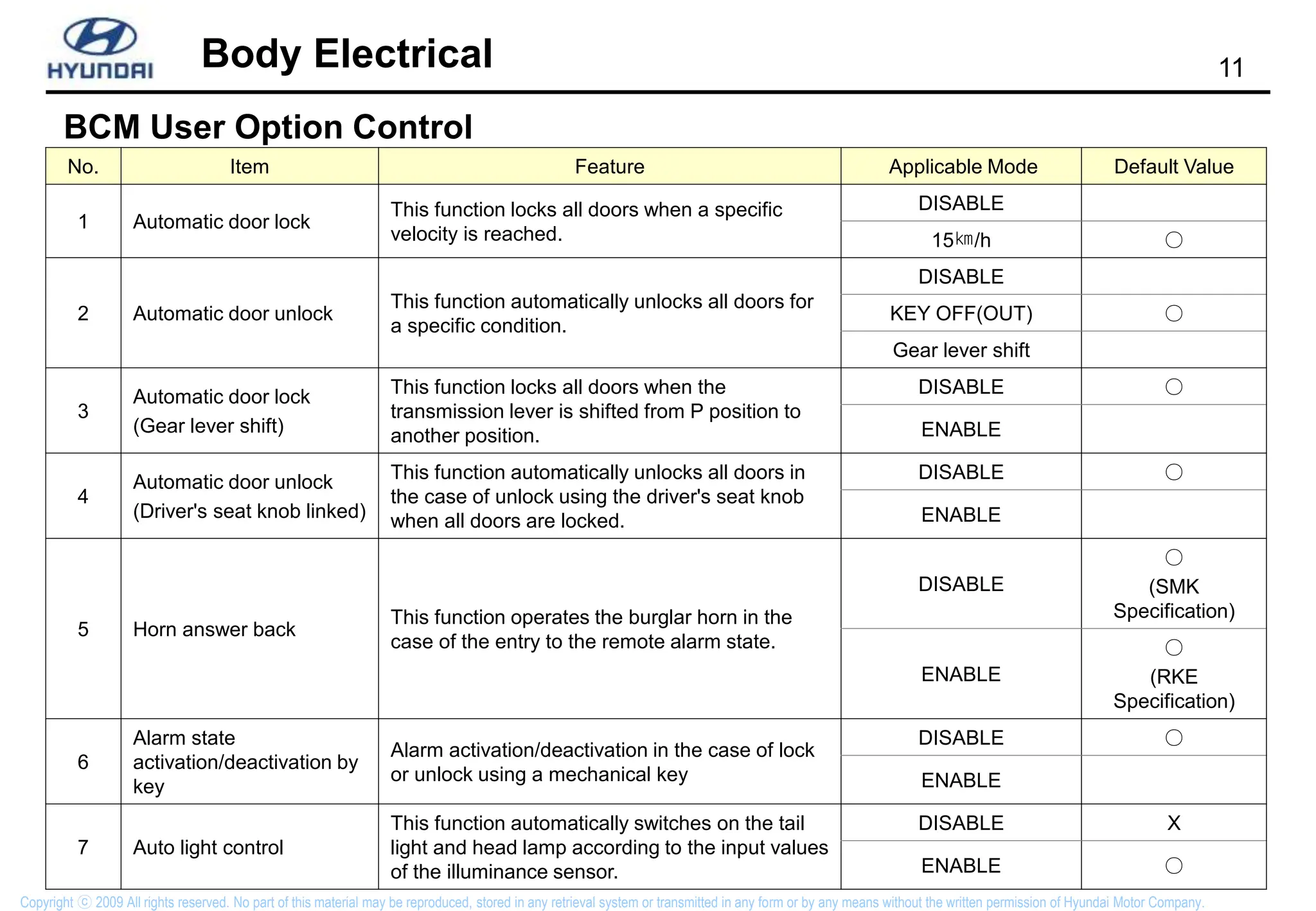
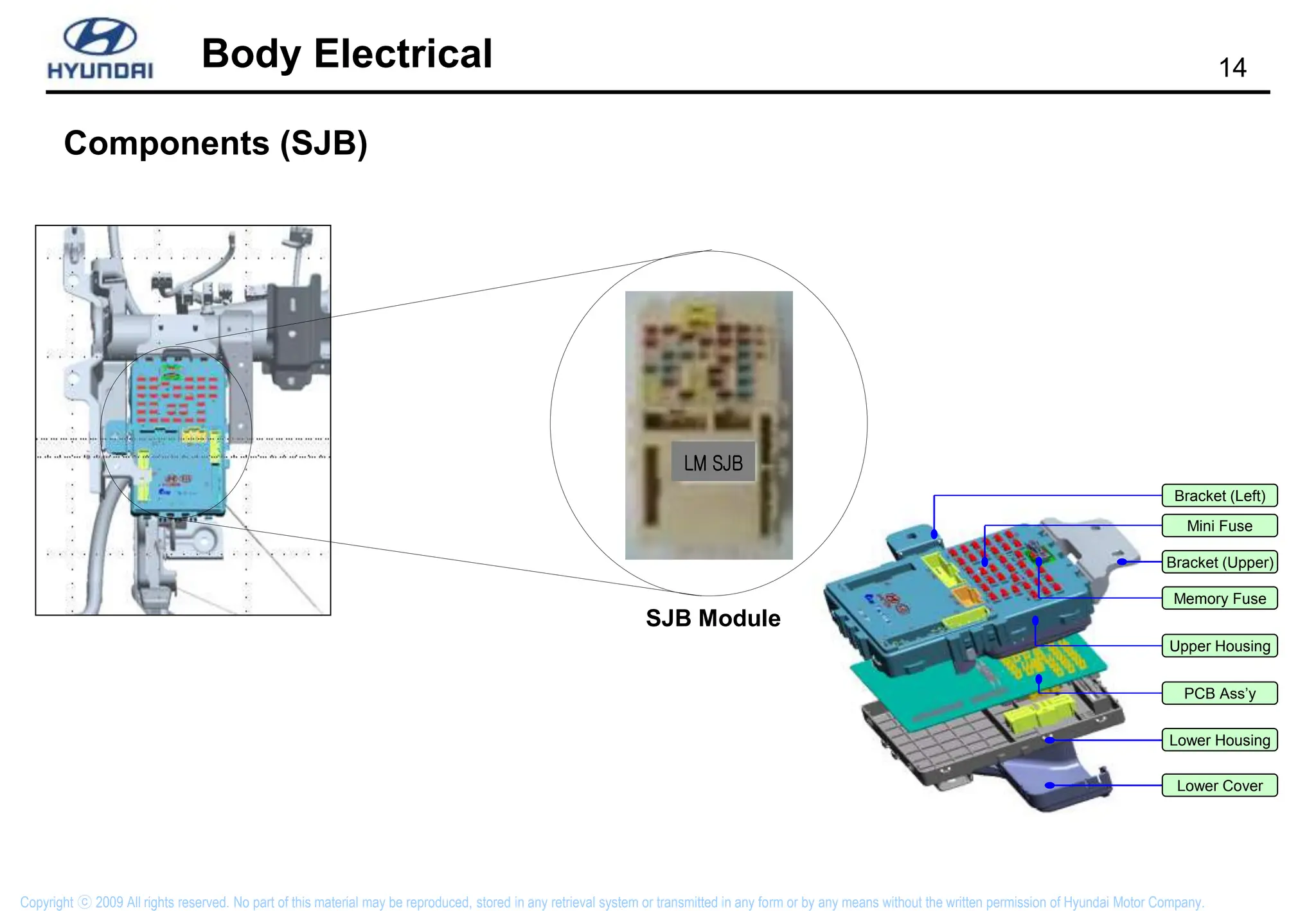
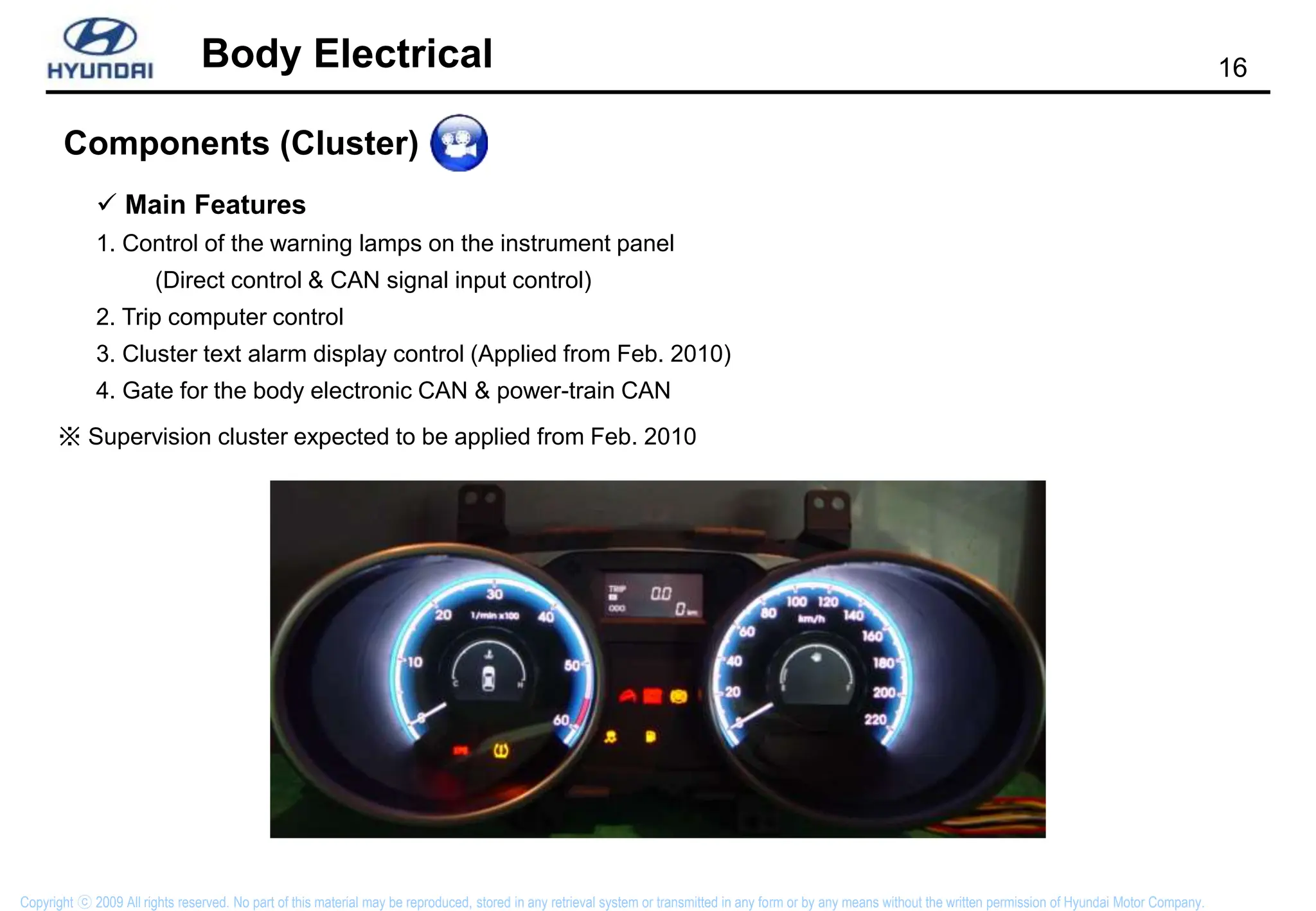
Body Electrical
LM SJB
LM SJB
Copyright ⓒ 2009 All rights reserved. No part of this material may be reproduced, stored in any retrieval system or transmitted in any form or by any means without the written permission of Hyundai Motor Company.
2
Body Electrical
Copyright ⓒ 2009 All rights reserved. No part of this material may be reproduced, stored in any retrieval system or transmitted in any form or by any means without the written permission of Hyundai Motor Company.
Body electrical communication (CAN)
Cluster Module
SJB
PDM
BCM
SMK
ECU
K-Line
K-Line
Power train CAN
(EMS,VDC..)
3
Body Electrical
Copyright ⓒ 2009 All rights reserved. No part of this material may be reproduced, stored in any retrieval system or transmitted in any form or by any means without the written permission of Hyundai Motor Company.
Body electrical communication (LIN)
Instrument Panel
BCM
(LIN Master)
RPAS
Digital Sensor
External Buzzer
CAN LIN
Built-in buzzer
4
Body Electrical
Copyright ⓒ 2009 All rights reserved. No part of this material may be reproduced, stored in any retrieval system or transmitted in any form or by any means without the written permission of Hyundai Motor Company.
Components (BCM)
 Main Features
1. CAN communication with SJB / Built-in RPAS module
2. Built-in RKE receiver (External receiver antenna)
3. Buzzer installed inside BCM
Connector
At the rear of the center fascia panel
5
Body Electrical
Copyright ⓒ 2009 All rights reserved. No part of this material may be reproduced, stored in any retrieval system or transmitted in any form or by any means without the written permission of Hyundai Motor Company.
Main BCM Control Features - New Features and Changes Only
Rear Intermittent Wiper Control (INT)
1) Detailed Input/Output
Classification Input/Output Type Detail
BCM Input Digital signals
IGN2
Rear wiper int. switch
BCM Output CAN output: BCM  SJB Rear wiper relay (Output from SJB)
T2
T1
Rear wiper
Relay
OFF
ON
Rear wiper
int. switch
(IGN2 ON)
OFF
ON
T1
T1:0.7s T2 : 5.3s
6
Body Electrical
Copyright ⓒ 2009 All rights reserved. No part of this material may be reproduced, stored in any retrieval system or transmitted in any form or by any means without the written permission of Hyundai Motor Company.
Main BCM Control Features - New Features and Changes Only
Internal Buzzer Control
Classification Input/Output Type Detail
BCM Input
Digital signals IGN1
CAN signal: CLUM → BCM
Tail light ON
Rheostat max/min brightness change signal
BCM Output Digital output Buzzer in BCM in operation for 0.4 s
1) Detailed Input/Output
2) Description of Detailed Features
OFF Buzzer Operation
Interior light OFF/IGN1 OFF
 Internal buzzer output OFF
(Interior light ON/IGN1 ON) & (Rheostat max/min brightness change: OFF  ON)
 Internal buzzer output ON - Operation started at 0.4 s cycle
7
Body Electrical
Copyright ⓒ 2009 All rights reserved. No part of this material may be reproduced, stored in any retrieval system or transmitted in any form or by any means without the written permission of Hyundai Motor Company.
1) Detailed Input/Output
2) Others
Classification Input/Output Type Detail
BCM Input
Digital signals
IGN1
Key In switch
CAN signal: SJB → BCM Four door switch state signal
BCM Output Digital output Photosensitive room lamp output for 30 s
① After the battery removal and installation, if IGN1 is on and four door switch is on (open), the room
lamp is switched on.
② After the battery removal and installation, if IGN1 is off and four door switch is on (open), the
maximum operation time of the room lamp is 20 minutes.
Main BCM Control Features - New Features and Changes Only
Decayed Room Lamp Control
8
Body Electrical
Copyright ⓒ 2009 All rights reserved. No part of this material may be reproduced, stored in any retrieval system or transmitted in any form or by any means without the written permission of Hyundai Motor Company.
Main BCM Control Features - New Features and Changes Only
Crash Unlock Control
1) Detailed Input/Output
Classification Input/Output Type Detail
BCM Input
Digital signals IGN1
PWM signal: From ACU Crash signal
BCM Output Digital output Door unlock relay
2) Description of Detailed Features
① ON/OFF judgment condition for the collision input signal
T2
(Crash Input)
HIGH
LOW
T1
T1: 16±2 msec , T2: 4±2 msec
OFF(Before crash) ON (After crash)
T2
T1
9
Body Electrical
Copyright ⓒ 2009 All rights reserved. No part of this material may be reproduced, stored in any retrieval system or transmitted in any form or by any means without the written permission of Hyundai Motor Company.
1) Control Condition
① When the remote unlock, smart key unlock or passive unlock signals are received, the door unlock
state signal is transmitted to the AV system 8 times.
2) Time chart
T2
T1
Not received
Received
Remote or
Passive
Unlock Signal
BCM  AV
T1,T2 : 60ms±ms
Main BCM Control Features - New Features and Changes Only
AV Unlock Signal Control (Door Unlock Signal)
10
Body Electrical
Copyright ⓒ 2009 All rights reserved. No part of this material may be reproduced, stored in any retrieval system or transmitted in any form or by any means without the written permission of Hyundai Motor Company.
Head lamp LOW switch H LP
TAIL
HI
Tail lamp switch
Head lamp HIGH switch
Multifunction Switch
Head lamp LOW control output
Autolight switch AUTO
PASSING
Front fog lamp switch FRT FOG
Rear fog lamp switch RR FOG
BCM
Main BCM Control Features - New Features and Changes Only
Head Lamp Control
11
Body Electrical
Copyright ⓒ 2009 All rights reserved. No part of this material may be reproduced, stored in any retrieval system or transmitted in any form or by any means without the written permission of Hyundai Motor Company.
No. Item Feature Applicable Mode Default Value
1 Automatic door lock
This function locks all doors when a specific
velocity is reached.
DISABLE
15㎞/h ○
2 Automatic door unlock
This function automatically unlocks all doors for
a specific condition.
DISABLE
KEY OFF(OUT) ○
Gear lever shift
3
Automatic door lock
(Gear lever shift)
This function locks all doors when the
transmission lever is shifted from P position to
another position.
DISABLE ○
ENABLE
4
Automatic door unlock
(Driver's seat knob linked)
This function automatically unlocks all doors in
the case of unlock using the driver's seat knob
when all doors are locked.
DISABLE ○
ENABLE
5 Horn answer back
This function operates the burglar horn in the
case of the entry to the remote alarm state.
DISABLE
○
(SMK
Specification)
ENABLE
○
(RKE
Specification)
6
Alarm state
activation/deactivation by
key
Alarm activation/deactivation in the case of lock
or unlock using a mechanical key
DISABLE ○
ENABLE
7 Auto light control
This function automatically switches on the tail
light and head lamp according to the input values
of the illuminance sensor.
DISABLE X
ENABLE ○
BCM User Option Control
12
Body Electrical
Copyright ⓒ 2009 All rights reserved. No part of this material may be reproduced, stored in any retrieval system or transmitted in any form or by any means without the written permission of Hyundai Motor Company.
Components (smart key ECU)
Smart Key (SMK) ECU
At the right side of the blower motor
13
Body Electrical
Copyright ⓒ 2009 All rights reserved. No part of this material may be reproduced, stored in any retrieval system or transmitted in any form or by any means without the written permission of Hyundai Motor Company.
Components (PDM)
Power Distribution Module
(PDM)
14
Body Electrical
Copyright ⓒ 2009 All rights reserved. No part of this material may be reproduced, stored in any retrieval system or transmitted in any form or by any means without the written permission of Hyundai Motor Company.
Bracket (Left)
Bracket (Upper)
Lower Cover
Mini Fuse
Memory Fuse
Upper Housing
PCB Ass’y
Lower Housing
Components (SJB)
LM SJB
LM SJB
SJB Module
16
Body Electrical
Copyright ⓒ 2009 All rights reserved. No part of this material may be reproduced, stored in any retrieval system or transmitted in any form or by any means without the written permission of Hyundai Motor Company.
Components (Cluster)
 Main Features
1. Control of the warning lamps on the instrument panel
(Direct control & CAN signal input control)
2. Trip computer control
3. Cluster text alarm display control (Applied from Feb. 2010)
4. Gate for the body electronic CAN & power-train CAN
※ Supervision cluster expected to be applied from Feb. 2010
17
Body Electrical
Copyright ⓒ 2009 All rights reserved. No part of this material may be reproduced, stored in any retrieval system or transmitted in any form or by any means without the written permission of Hyundai Motor Company.
Components (RPASM : Rear Parking Assist System Module)
Sensor 1
(RL)
Sensor 2
(RCL)
Sensor 3
(RCR)
Sensor 4
(RR)
※ Sensor beam width: 100˚ horizontal and 40˚ vertical
(for a single sensor)
1 6
 Main Features
1.Transmission of the data on the distance to the obstacle upon the distance
measurement request of the BCM (As a slave module)
2. Transmission of fault data to the BCM
3. IGN ON, R gear engagement and distance measurement request of BCM
(master module)  LIN communication started
18
Body Electrical
Copyright ⓒ 2009 All rights reserved. No part of this material may be reproduced, stored in any retrieval system or transmitted in any form or by any means without the written permission of Hyundai Motor Company.
ESS (Emergency Stop Signal)
: C-CAN
: B-CAN
: Hard-wire
B+
BLS
ESS Relay (NC)
IGN
BS
ABS
ESC
Hazard
Switch
BCM
Gateway
(Cluster)
• Hazard Switch
-ON
-OFF
“ON/OFF”
signal
Lamp Control
(Blinking)
Relay State Monitoring
• Hazard Switch
-ON
-OFF
STOP Lamp
(include High-Mount-Stop-Lamp)
Direction Ind. Lamp
• ESS function
-Inactive
-Active
-Defective
• ESS function
-Inactive
-Active Lamp Control
(Blinking)
※ Applicable region (Time): Korea (Aug. 2009) / Europe (Feb. 2010)
21
Body Electrical
Copyright ⓒ 2009 All rights reserved. No part of this material may be reproduced, stored in any retrieval system or transmitted in any form or by any means without the written permission of Hyundai Motor Company.
RPAS (Rear Parking Assist System)
40CM
80CM
120CM
RL RCL RCR RR
Horizontal Detection Range Vertical Detection Range

Hyundai Electrical System Body training service

  • 1.
    Body Electrical LM SJB LMSJB Copyright ⓒ 2009 All rights reserved. No part of this material may be reproduced, stored in any retrieval system or transmitted in any form or by any means without the written permission of Hyundai Motor Company.
  • 2.
    2 Body Electrical Copyright ⓒ2009 All rights reserved. No part of this material may be reproduced, stored in any retrieval system or transmitted in any form or by any means without the written permission of Hyundai Motor Company. Body electrical communication (CAN) Cluster Module SJB PDM BCM SMK ECU K-Line K-Line Power train CAN (EMS,VDC..)
  • 3.
    3 Body Electrical Copyright ⓒ2009 All rights reserved. No part of this material may be reproduced, stored in any retrieval system or transmitted in any form or by any means without the written permission of Hyundai Motor Company. Body electrical communication (LIN) Instrument Panel BCM (LIN Master) RPAS Digital Sensor External Buzzer CAN LIN Built-in buzzer
  • 4.
    4 Body Electrical Copyright ⓒ2009 All rights reserved. No part of this material may be reproduced, stored in any retrieval system or transmitted in any form or by any means without the written permission of Hyundai Motor Company. Components (BCM)  Main Features 1. CAN communication with SJB / Built-in RPAS module 2. Built-in RKE receiver (External receiver antenna) 3. Buzzer installed inside BCM Connector At the rear of the center fascia panel
  • 5.
    5 Body Electrical Copyright ⓒ2009 All rights reserved. No part of this material may be reproduced, stored in any retrieval system or transmitted in any form or by any means without the written permission of Hyundai Motor Company. Main BCM Control Features - New Features and Changes Only Rear Intermittent Wiper Control (INT) 1) Detailed Input/Output Classification Input/Output Type Detail BCM Input Digital signals IGN2 Rear wiper int. switch BCM Output CAN output: BCM  SJB Rear wiper relay (Output from SJB) T2 T1 Rear wiper Relay OFF ON Rear wiper int. switch (IGN2 ON) OFF ON T1 T1:0.7s T2 : 5.3s
  • 6.
    6 Body Electrical Copyright ⓒ2009 All rights reserved. No part of this material may be reproduced, stored in any retrieval system or transmitted in any form or by any means without the written permission of Hyundai Motor Company. Main BCM Control Features - New Features and Changes Only Internal Buzzer Control Classification Input/Output Type Detail BCM Input Digital signals IGN1 CAN signal: CLUM → BCM Tail light ON Rheostat max/min brightness change signal BCM Output Digital output Buzzer in BCM in operation for 0.4 s 1) Detailed Input/Output 2) Description of Detailed Features OFF Buzzer Operation Interior light OFF/IGN1 OFF  Internal buzzer output OFF (Interior light ON/IGN1 ON) & (Rheostat max/min brightness change: OFF  ON)  Internal buzzer output ON - Operation started at 0.4 s cycle
  • 7.
    7 Body Electrical Copyright ⓒ2009 All rights reserved. No part of this material may be reproduced, stored in any retrieval system or transmitted in any form or by any means without the written permission of Hyundai Motor Company. 1) Detailed Input/Output 2) Others Classification Input/Output Type Detail BCM Input Digital signals IGN1 Key In switch CAN signal: SJB → BCM Four door switch state signal BCM Output Digital output Photosensitive room lamp output for 30 s ① After the battery removal and installation, if IGN1 is on and four door switch is on (open), the room lamp is switched on. ② After the battery removal and installation, if IGN1 is off and four door switch is on (open), the maximum operation time of the room lamp is 20 minutes. Main BCM Control Features - New Features and Changes Only Decayed Room Lamp Control
  • 8.
    8 Body Electrical Copyright ⓒ2009 All rights reserved. No part of this material may be reproduced, stored in any retrieval system or transmitted in any form or by any means without the written permission of Hyundai Motor Company. Main BCM Control Features - New Features and Changes Only Crash Unlock Control 1) Detailed Input/Output Classification Input/Output Type Detail BCM Input Digital signals IGN1 PWM signal: From ACU Crash signal BCM Output Digital output Door unlock relay 2) Description of Detailed Features ① ON/OFF judgment condition for the collision input signal T2 (Crash Input) HIGH LOW T1 T1: 16±2 msec , T2: 4±2 msec OFF(Before crash) ON (After crash) T2 T1
  • 9.
    9 Body Electrical Copyright ⓒ2009 All rights reserved. No part of this material may be reproduced, stored in any retrieval system or transmitted in any form or by any means without the written permission of Hyundai Motor Company. 1) Control Condition ① When the remote unlock, smart key unlock or passive unlock signals are received, the door unlock state signal is transmitted to the AV system 8 times. 2) Time chart T2 T1 Not received Received Remote or Passive Unlock Signal BCM  AV T1,T2 : 60ms±ms Main BCM Control Features - New Features and Changes Only AV Unlock Signal Control (Door Unlock Signal)
  • 10.
    10 Body Electrical Copyright ⓒ2009 All rights reserved. No part of this material may be reproduced, stored in any retrieval system or transmitted in any form or by any means without the written permission of Hyundai Motor Company. Head lamp LOW switch H LP TAIL HI Tail lamp switch Head lamp HIGH switch Multifunction Switch Head lamp LOW control output Autolight switch AUTO PASSING Front fog lamp switch FRT FOG Rear fog lamp switch RR FOG BCM Main BCM Control Features - New Features and Changes Only Head Lamp Control
  • 11.
    11 Body Electrical Copyright ⓒ2009 All rights reserved. No part of this material may be reproduced, stored in any retrieval system or transmitted in any form or by any means without the written permission of Hyundai Motor Company. No. Item Feature Applicable Mode Default Value 1 Automatic door lock This function locks all doors when a specific velocity is reached. DISABLE 15㎞/h ○ 2 Automatic door unlock This function automatically unlocks all doors for a specific condition. DISABLE KEY OFF(OUT) ○ Gear lever shift 3 Automatic door lock (Gear lever shift) This function locks all doors when the transmission lever is shifted from P position to another position. DISABLE ○ ENABLE 4 Automatic door unlock (Driver's seat knob linked) This function automatically unlocks all doors in the case of unlock using the driver's seat knob when all doors are locked. DISABLE ○ ENABLE 5 Horn answer back This function operates the burglar horn in the case of the entry to the remote alarm state. DISABLE ○ (SMK Specification) ENABLE ○ (RKE Specification) 6 Alarm state activation/deactivation by key Alarm activation/deactivation in the case of lock or unlock using a mechanical key DISABLE ○ ENABLE 7 Auto light control This function automatically switches on the tail light and head lamp according to the input values of the illuminance sensor. DISABLE X ENABLE ○ BCM User Option Control
  • 12.
    12 Body Electrical Copyright ⓒ2009 All rights reserved. No part of this material may be reproduced, stored in any retrieval system or transmitted in any form or by any means without the written permission of Hyundai Motor Company. Components (smart key ECU) Smart Key (SMK) ECU At the right side of the blower motor
  • 13.
    13 Body Electrical Copyright ⓒ2009 All rights reserved. No part of this material may be reproduced, stored in any retrieval system or transmitted in any form or by any means without the written permission of Hyundai Motor Company. Components (PDM) Power Distribution Module (PDM)
  • 14.
    14 Body Electrical Copyright ⓒ2009 All rights reserved. No part of this material may be reproduced, stored in any retrieval system or transmitted in any form or by any means without the written permission of Hyundai Motor Company. Bracket (Left) Bracket (Upper) Lower Cover Mini Fuse Memory Fuse Upper Housing PCB Ass’y Lower Housing Components (SJB) LM SJB LM SJB SJB Module
  • 15.
    16 Body Electrical Copyright ⓒ2009 All rights reserved. No part of this material may be reproduced, stored in any retrieval system or transmitted in any form or by any means without the written permission of Hyundai Motor Company. Components (Cluster)  Main Features 1. Control of the warning lamps on the instrument panel (Direct control & CAN signal input control) 2. Trip computer control 3. Cluster text alarm display control (Applied from Feb. 2010) 4. Gate for the body electronic CAN & power-train CAN ※ Supervision cluster expected to be applied from Feb. 2010
  • 16.
    17 Body Electrical Copyright ⓒ2009 All rights reserved. No part of this material may be reproduced, stored in any retrieval system or transmitted in any form or by any means without the written permission of Hyundai Motor Company. Components (RPASM : Rear Parking Assist System Module) Sensor 1 (RL) Sensor 2 (RCL) Sensor 3 (RCR) Sensor 4 (RR) ※ Sensor beam width: 100˚ horizontal and 40˚ vertical (for a single sensor) 1 6  Main Features 1.Transmission of the data on the distance to the obstacle upon the distance measurement request of the BCM (As a slave module) 2. Transmission of fault data to the BCM 3. IGN ON, R gear engagement and distance measurement request of BCM (master module)  LIN communication started
  • 17.
    18 Body Electrical Copyright ⓒ2009 All rights reserved. No part of this material may be reproduced, stored in any retrieval system or transmitted in any form or by any means without the written permission of Hyundai Motor Company. ESS (Emergency Stop Signal) : C-CAN : B-CAN : Hard-wire B+ BLS ESS Relay (NC) IGN BS ABS ESC Hazard Switch BCM Gateway (Cluster) • Hazard Switch -ON -OFF “ON/OFF” signal Lamp Control (Blinking) Relay State Monitoring • Hazard Switch -ON -OFF STOP Lamp (include High-Mount-Stop-Lamp) Direction Ind. Lamp • ESS function -Inactive -Active -Defective • ESS function -Inactive -Active Lamp Control (Blinking) ※ Applicable region (Time): Korea (Aug. 2009) / Europe (Feb. 2010)
  • 18.
    21 Body Electrical Copyright ⓒ2009 All rights reserved. No part of this material may be reproduced, stored in any retrieval system or transmitted in any form or by any means without the written permission of Hyundai Motor Company. RPAS (Rear Parking Assist System) 40CM 80CM 120CM RL RCL RCR RR Horizontal Detection Range Vertical Detection Range

Editor's Notes

  • #2 Material: Training vehicle (LM) Training Part (BCM) Hi-scan Pro / GDS Instructors guide Trainees textbook / File Practice sheets (Practice preparation) Workshop manuals Certificates Nameplates (Paper for notes) (Pens etc.) Method: Lecture Practice Task Lead over: Lets have a look at the CAN communication.
  • #3 Material: Trainees textbook Method: Lecture Question Lead over: Lets have a look at the LIN communication.
  • #4 Material: Trainees textbook Method: Lecture Question Lead over: Lets move to BCM main function.
  • #5 Material: Trainees textbook Method: Lecture Question Task Lead over: Lets have a look at the changed thing of BCM function.
  • #6 Material: Trainees textbook Method: Lecture Question Task Lead over: Lets have a look at the changed thing of BCM function.
  • #7 Internal Buzzer Control
  • #8  This is a new feature. When IGN1 is off and the key is in, with four doors closed, key-off operation will switch on the room lamp for 30 seconds and then switch it off. The other features are the same as those of the existing vehicle.
  • #9  The door unlock relay is controlled in the same manner as in the existing vehicle, but the collision signals inputted in the BCM are PWM signals, instead of ON/OFF signals.
  • #10 AV Unlock Signal Control (Door Unlock Signal)
  • #11  The head lamp control features of the LM vehicle include LOW, HIGH, PASSING and ESCORT functions. The head lamp LOW and ESCORT features existed in the BCM of the existing vehicle, and the head lamp HIGH and PASSING features are newly added to the BCM control items. In this chapter, you will learn the detailed input/output and control condition that are required to operate the head lamp HIGH and PASSING features to accurately diagnose the faults in the vehicle.
  • #12  The BCM of the LM vehicle supports diverse user options and features.
  • #13 Components (smart key ECU)
  • #14 Components (PDM)
  • #15 Components (SJB)
  • #16 Components (SJB)
  • #17 Components (Cluster)
  • #18 RPASM : Rear Parking Assist System Module
  • #19 ESS (Emergency Stop Signal)
  • #20 4) ESS Activation Condition
  • #21 Additional Feature Control Condition
  • #22 RPAS (Rear Parking Assist System)
  • #23 RPAS (Rear Parking Assist System)
  • #24 RPAS (Rear Parking Assist System)