Downloaded 104 times
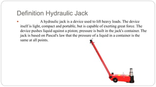
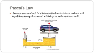
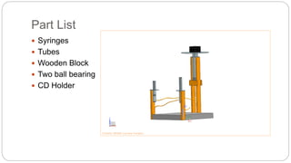
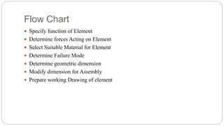
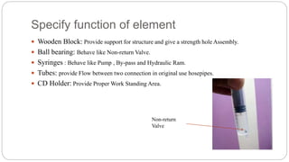
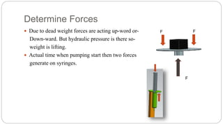
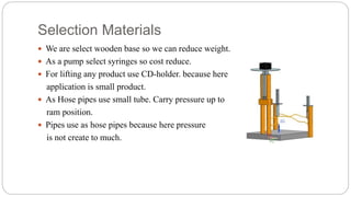
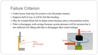
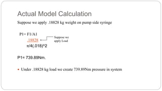
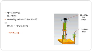
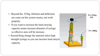
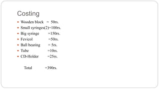


The document describes the design and working of a hydraulic jack. It consists of syringes that act as a pump and ram, tubes to connect them, a wooden block for support, and ball bearings as non-return valves. When the small syringe is pushed in, it transmits pressure undiminished to the large syringe due to Pascal's law, lifting a load. The document outlines the components, design process including determining forces and dimensions, and provides calculations showing it can lift a 0.523 kg load. It also discusses potential improvements such as increasing diameters or using pneumatics.


