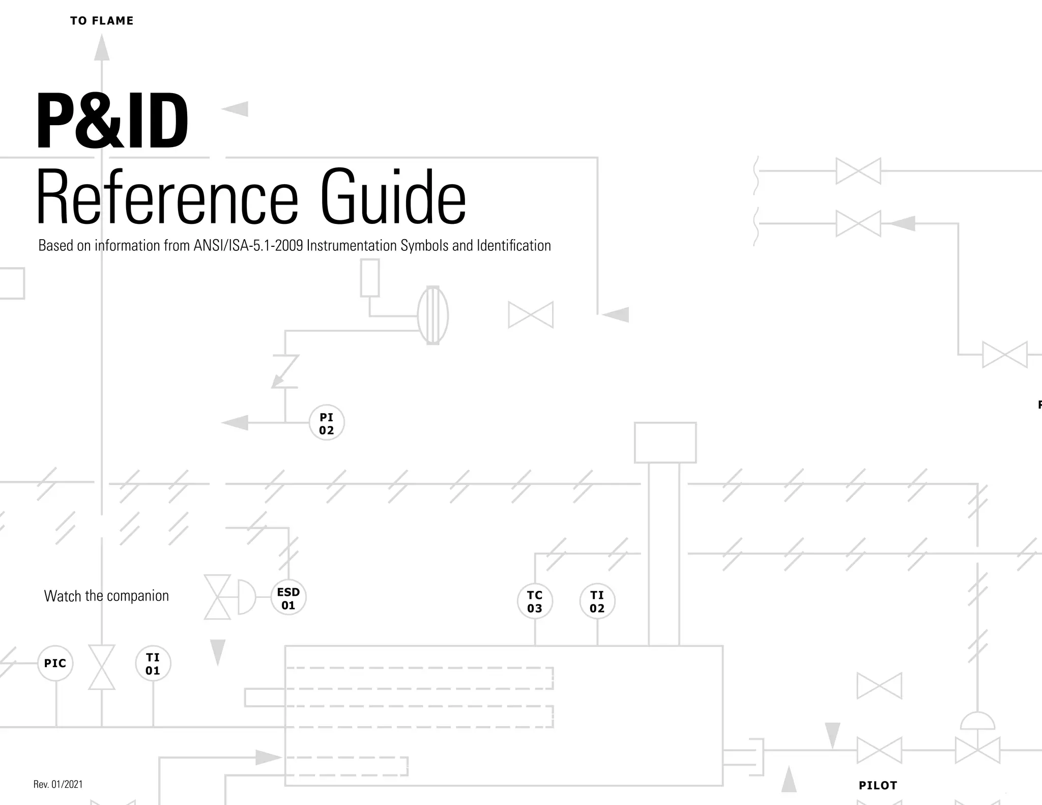
This document provides information on instrumentation symbols and identification based on ANSI/ISA-5.1-2009 standards. It includes:
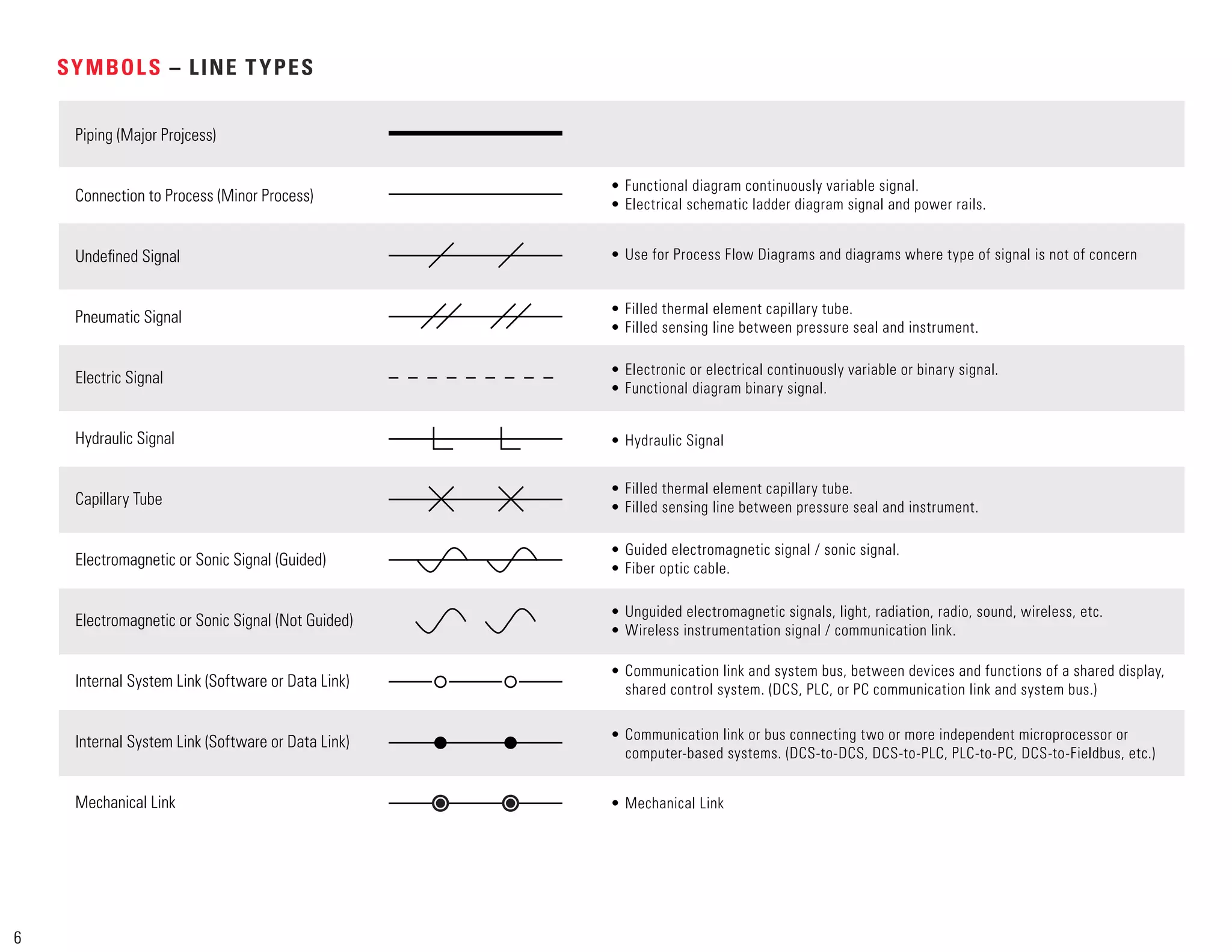
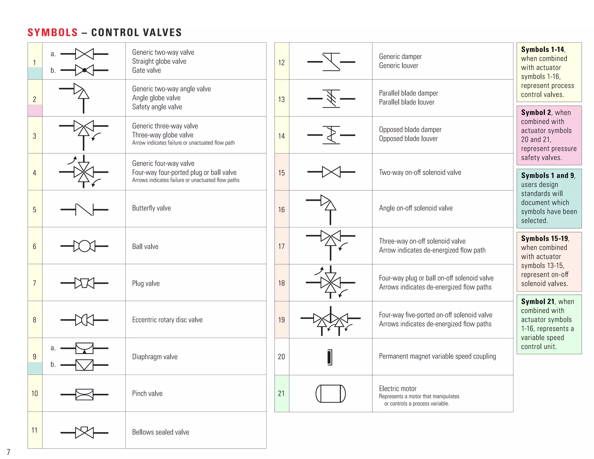
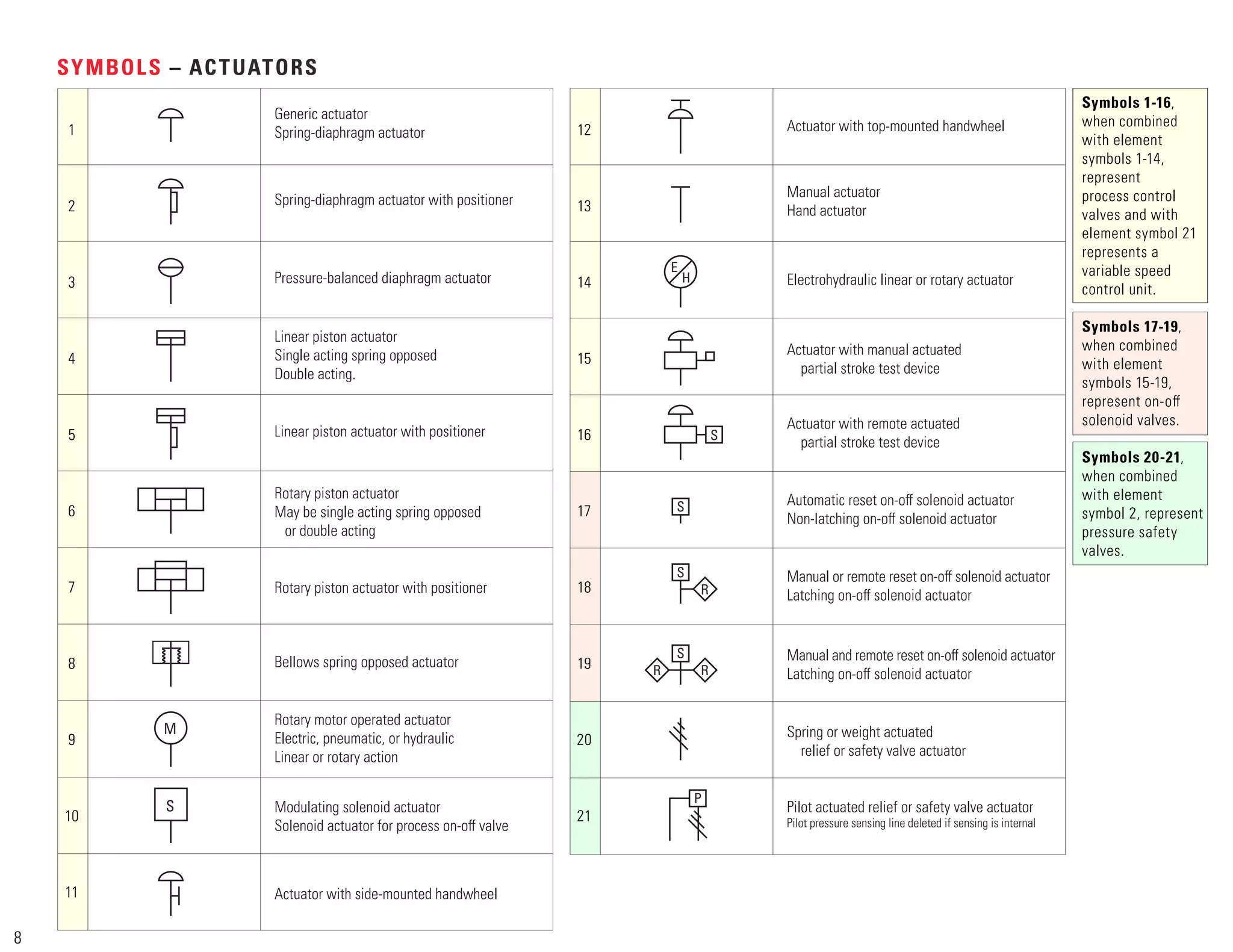
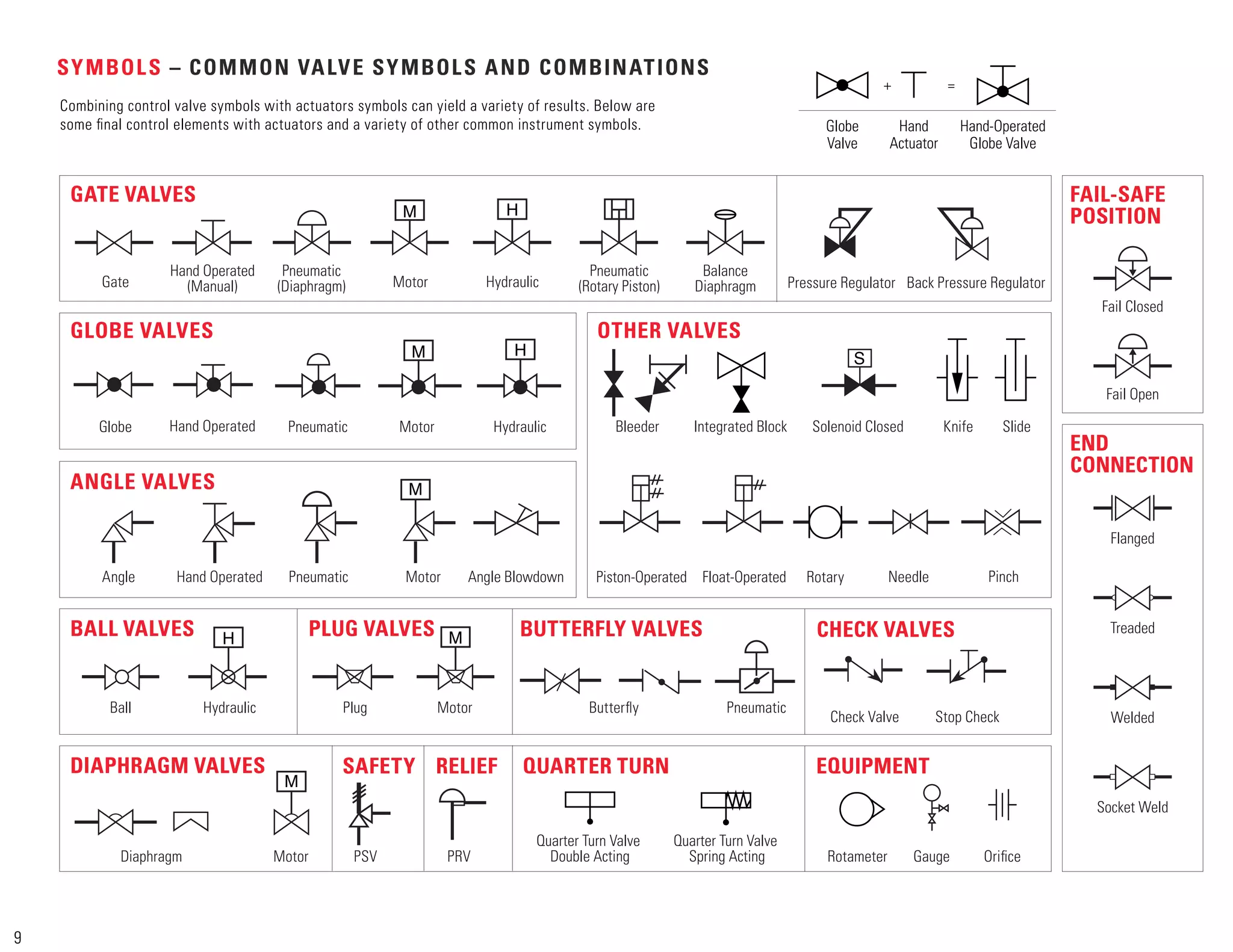
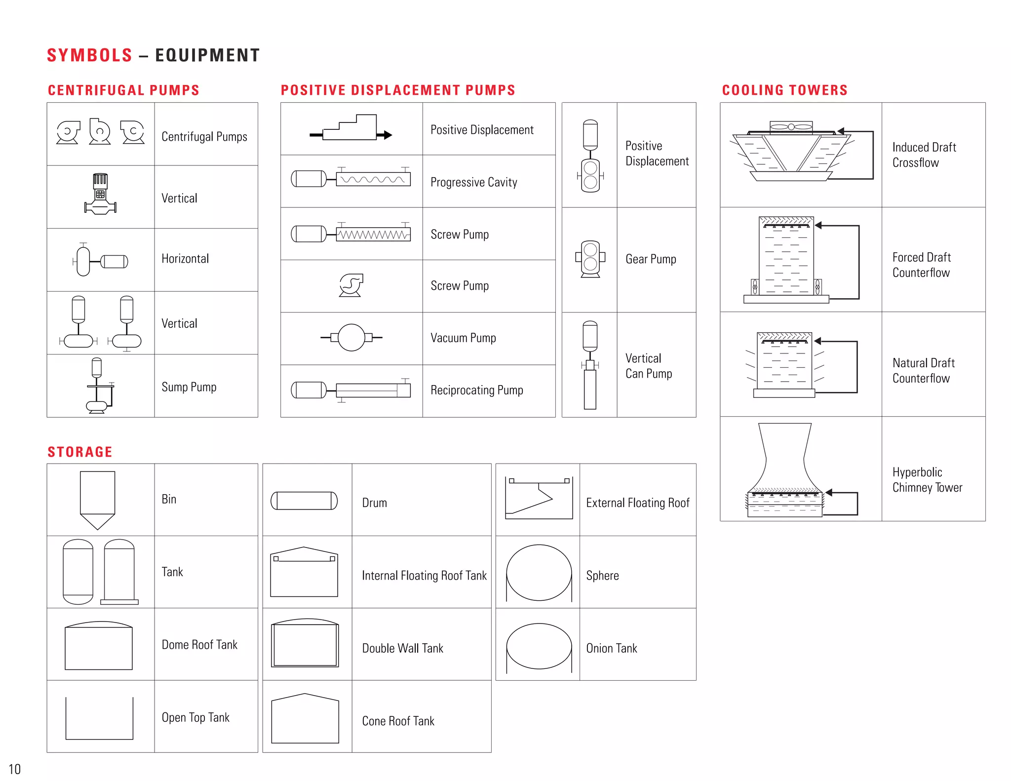
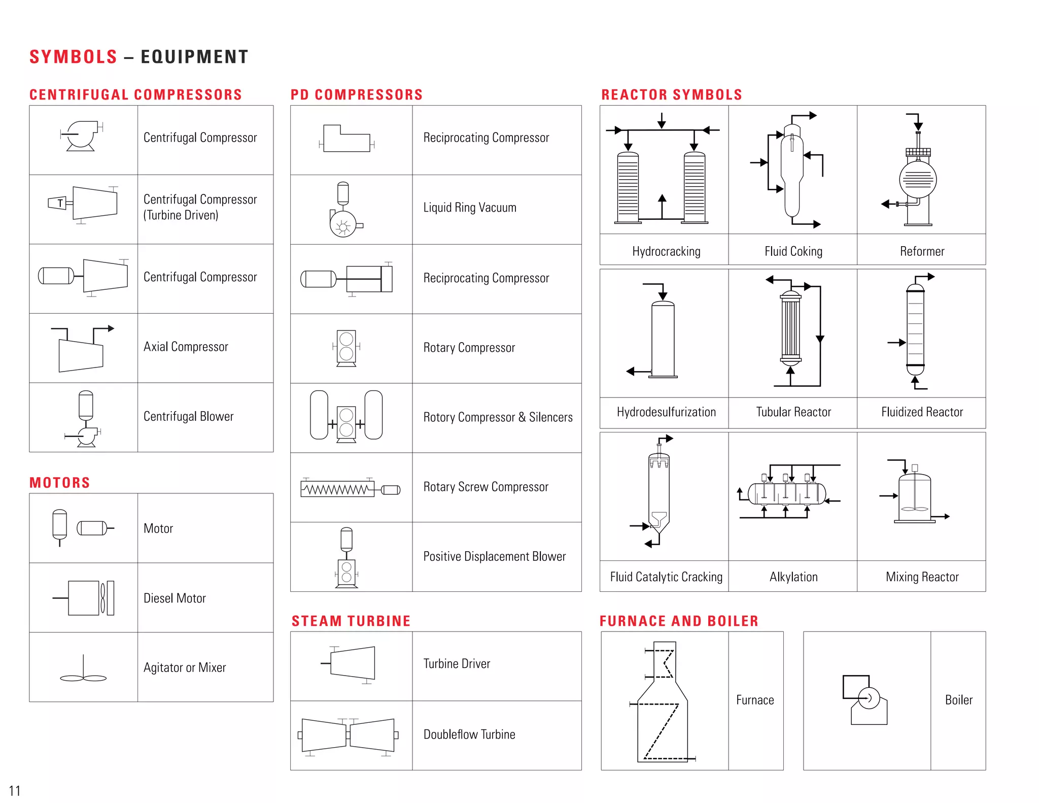
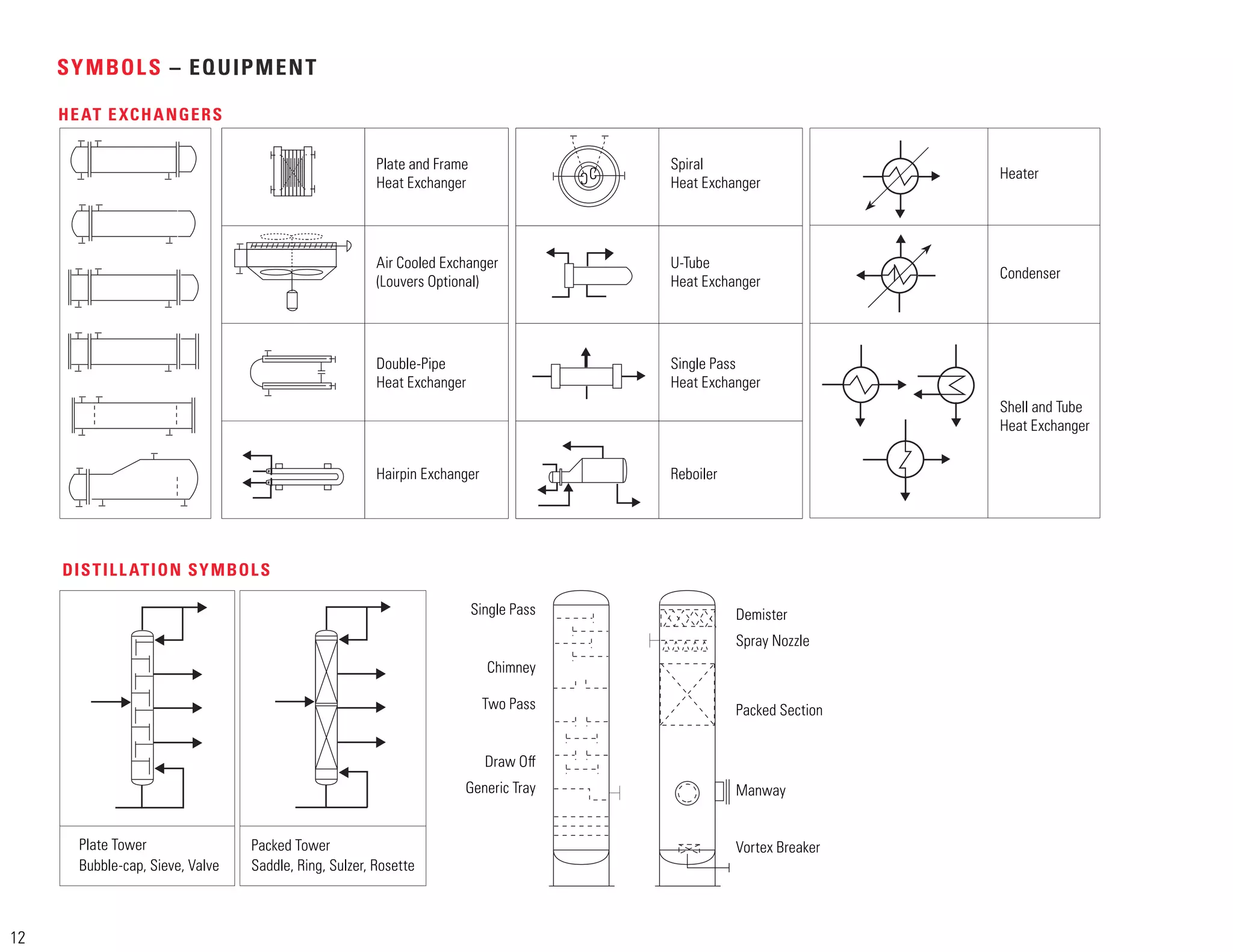
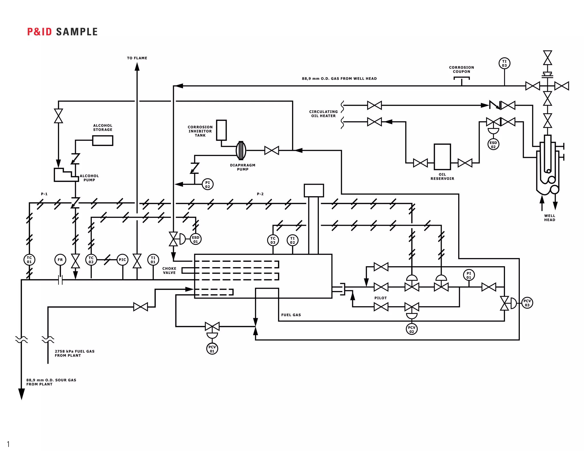
1) Common control valve, actuator, and instrument symbols used in process and instrumentation diagrams along with brief descriptions.
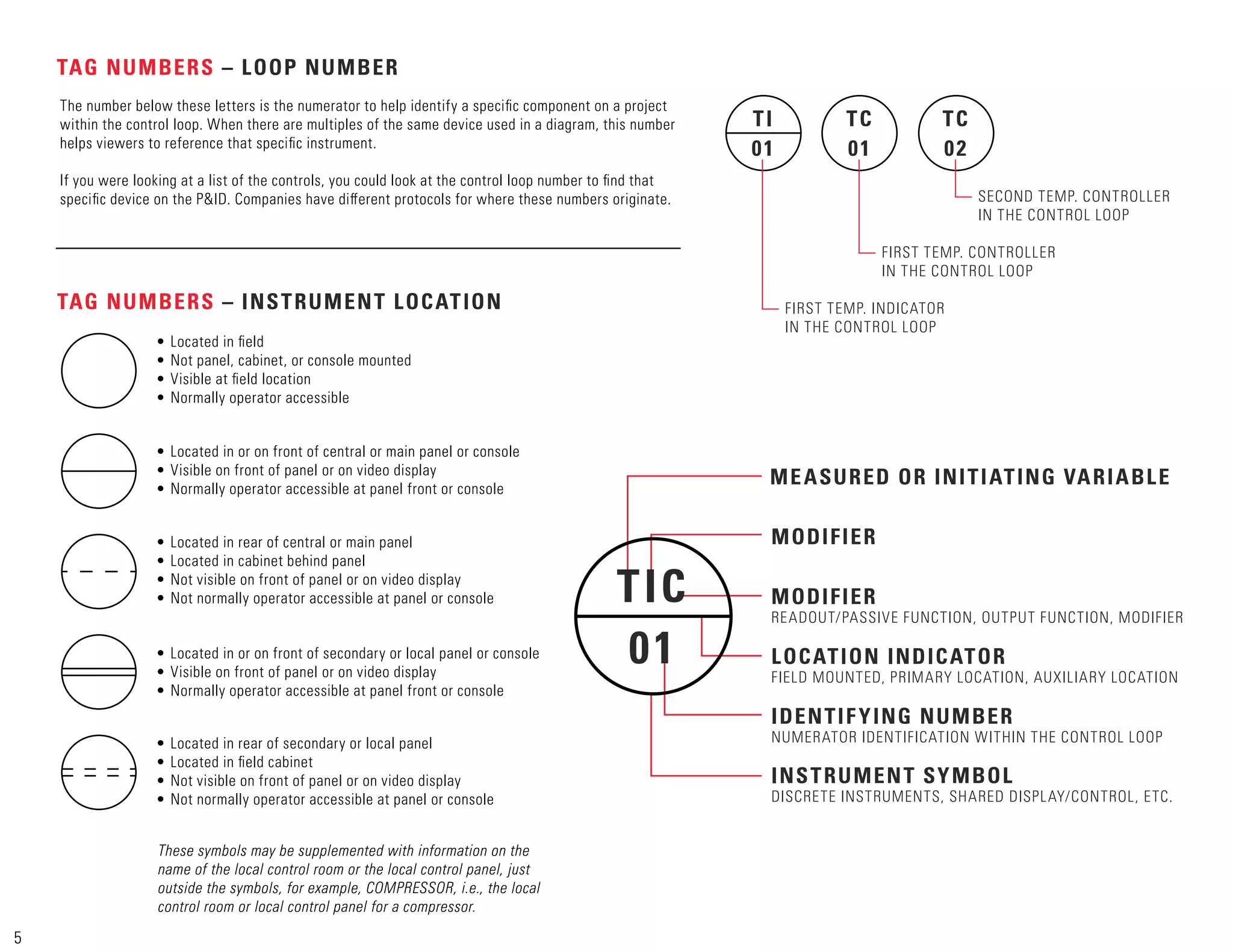
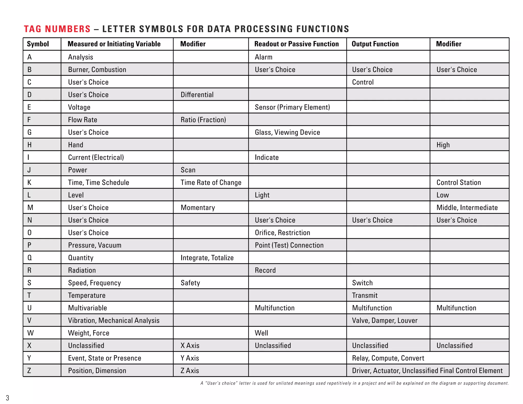
2) Guidelines for assigning tag numbers and abbreviations to identify process variables, locations, and loop identifiers for instruments.
3) Examples of standard tag number prefixes and abbreviations used in oil and gas applications to indicate instrument types and functions.
![A Analog Signal
AC Analysis Controller
AAH Analysis Alarm [High]
AAHL Analysis Alarm [High/Low]
AAL Analysis Alarm [Low]
AS Air Supply
ASDH Analysis Shutdown [High]
ASDL Analysis Shutdown [Low]
ASH Analysis Switch [High]
ASHL Analysis Switch [High/Low]
ASL Analysis Switch [Low]
AT Analysis Transmitter
BC Burner Controller
BAH Burner Alarm [High]
BAHL Burner Alarm [High/Low]
BAL Burner Alarm [Low]
BDV Blowdown Valve
BPR Back Pressure Regulator
BS Burner Switch
BSH Burner Switch [High]
BSHL Burner Switch [High/Low]
BSL Burner Switch [Low]
BS&W Basic Sediment and Water
CCP Central Control Panel
CDS Compressor Shutdown
CFA Common Fault Alarm
COR Corrosimeter
CSC Car Seal Close
CSO Car Seal Open
CV Control Valve
E/I EMF to Current Converter
ES Electrical Switch
ESD Emergency Shutdown Station
ESDV Emergency Shutdown Valve
FAL Flow Alarm Low
FAH Flow Alarm High
FAHH Flow Alarm High For Level Above FAH
FAHL Flow Alarm [High/Low]
FALL Flow Alarm Low For Level Below FAL
FC Flow Controller
FC Fail Close
FCV Flow Control Valve
FE Flow Element
FFA Flame Failure Alarm
FFSD Flame Failure Shutdown
FG Flow Gage/Flow Sight Glass
FI Flow Indicator
FIC Flow Indicator Controller
FIT Flow Indicator Transmitter
TAG NUMBERS – OIL & GAS INSTRUMENT ABBREVIATIONS (Adapted From ISA Standard S5.1)
4
FO Fial Open
FQ Flow Indicator Totaliser
FQI Flow Indicator with Total Counter
FR Flow Recorder
FRC Flow Recorder Controller
FRT Flow Recorder Transmitter
FS Flow Switch
FSDH Flow Shutdown [High]
FSDL Flow Shutdown [Low]
FSH Flow Switch [High]
FSL Flow Switch [Low]
FT Flow Transmitter
FY Computer, Relay, Amplifier or I/P
Converter in Flow Loop
GS Instrument Gas Supply
H Hydraulic
HMV Hydraulic Motor Operated Valve
HOA Hand/Off/Auto Switch
HS Hand Switch
I Current Signal
I/F Interface
I/I Current Indicator
I/P Current to Pneumatic
I/PA Current to Pneumatic Alarm
KI Clock/Timer
LA Level Alarm
LAH Level Alarm [High]
LAHH Level Alarm High for Level Above LAH
LAHL Level Alarm [High/Low]
LAL Level Alarm [Low]
LALL Level Alarm Low for Level Above LAL
LC Level Controller
LCV Level Control Valve
LG Level Gauge
LI Level Indicator
LIC Level Indicator Controller
LIT Level Indicator Transmitter
LLH Liquid Level [High]
LLL Liquid Level [Low]
LLN Liquid Level [Normal]
LQ Lock Closed When by a manual Valve
LR Level Recorder
LS Level Switch
LSDH Level Shutdown [High]
LSDL Level Shutdown [Low]
LSH Level Switch [High]
LSHL Level Switch [High/Low]
LSL Level Switch [Low]
LSHH Level Switch High for Level Above LSH
LSLL Level Switch Low for Level Below LSL
LT Level Transmitter
LY I/P Converter [Level Loop]
LO Lock Open
MCC Motor Control Center
MTU Master Terminal Unit
NC Normally Closed
NO Normally Open
P Pneumatic Signal
PAH Pressure Alarm [High]
PAHL Pressure Alarm [High/Low]
PAL Pressure Alarm [Low]
PB Pushbutton
PC Pressure Controller
PCV Pressure Control Valve
PD Pulsation Dampener
PdA Pressure Differential Alarm
PdAH Pressure Differential Alarm [High]
PdAL Pressure Differential Alarm [Low]
PdI Pressure Differential Indicator
PdIC Pressure Differential Indicator Controller
PdS Pressure Differential Switch
PdSH Pressure Differential Switch [High]
PdSL Pressure Differential Switch [Low]
PG Pressure Gage
P/I Pneumatic To Current Converter
PI Pressure Indicator
PIC Pressure Indicator Controller
PIT Pressure Indicator Transmitter
PJI Multipoint Pressure Indicator
PJR Multipoint Pressure Recorder
POV Pneumatically Operated Valve
PR Pressure Recorder
PRC Pressure Recorder Controller
PRT Pressure Recorder Transmitter
PRV Pressure Regulating Valve
PSDH Pressure Shutdown [High]
PSDL Pressure Shutdown [Low]
PSE Rupture Disk
PSH Pressure Switch [High]
PSHH Pressure Switch High for Pressure Above PSH
PSHL Pressure Switch [High/Low]
PSL Pressure Switch [Low]
PSLL Pressure Switch Low for Pressure Below PSL
PSV Pressure Safety Valve
PT Pressure Transmitter
POS Positioner
PY Relay, Computer, Amplifier, Converter or
I/P Converter etc/ in Pressure Loop
RC Ratio Controller
RTD Resistance Temperature Detector
RTU Remote Terminal Unit
S Solenoid
SAH Speed Alarm [High]
SAHL Speed Alarm [High/Low]
SAL Speed Alarm [Low]
SC Sample Connection
SD Shutdown Panel
SI Speed Indicator
SR Speed Recorder
SS Steam Supply
SSH Speed Switch [High]
SSHL Speed Switch [High/Low]
SSL Speed Switch [Low]
TAH Temperature Alarm [High]
TAHL Temperature Alarm [High/Low]
TAL Temperature Alarm [Low]
TC Temperature Controller
TCV Temperature Control Valve
TD Time Delay
TE Temperature [Measuring] Element/Thermocouple
TF Temperature Gage
TH Thermostat
TI Temperature Indicator
TIC Temperature Indicator Controller
TIT Temperature Indicator Transmitter
TJI Multipoint Temperature Indicator/Thermocouple
TR Temperature Recorder
TRC Temperature Recorder Controller
TRT Temperature Recorder Transmitter
TSDH Temperature Shutdown [High]
TSDL Temperature Shutdown [Low]
TSH Temperature Switch [High]
TSHL Temperature Switch [High/Low]
TSL Temperature Switch [Low]
TT Temperature Transmitter
TW Thermowell
TY Computer, Relay, Converter, etc. in Temp. Loop
US Utility Station
VAH Vibration Alarm [High]
VSDH Vibration Shutdown [High]
VSH Vibration Switch [High]
WS Water Supply
X Multiply
ZC Position Switch [Closed]
ZO Position Switch [Open]](https://image.slidesharecdn.com/how-toreadpidreferenceguide-220825170905-01cd8ebb/75/How-to-read-P-ID-Reference-Guide-pdf-5-2048.jpg)