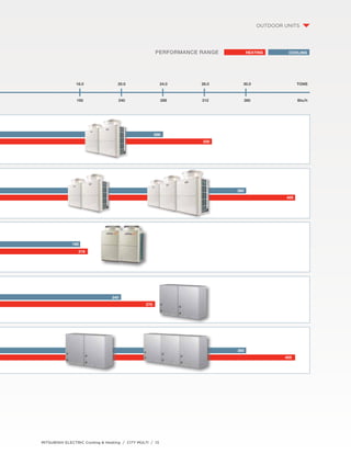
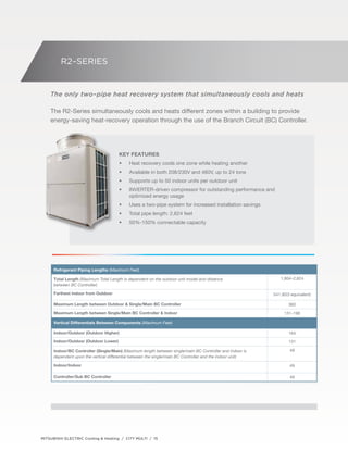
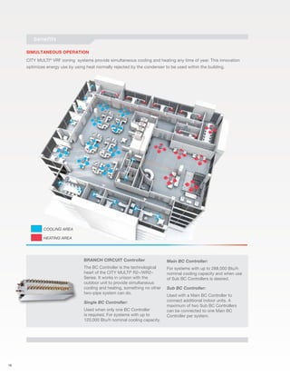
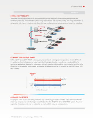
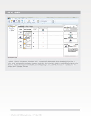
This document provides an overview and specifications for Mitsubishi Electric's CITY MULTI variable refrigerant flow zoning systems. It introduces their line of outdoor units, including the R2-Series, Y-Series, H2i Y-Series, S-Series, and W-Series. It also describes their indoor units and control options. The document is intended to showcase Mitsubishi Electric's products and solutions for variable refrigerant flow zoning applications.


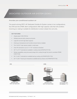


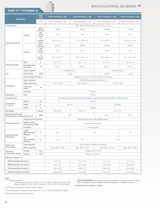
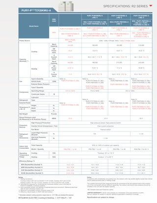
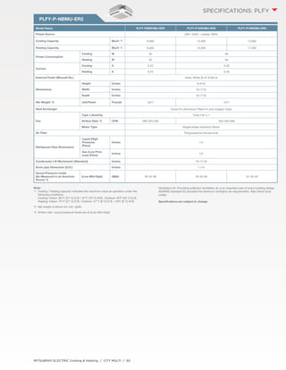
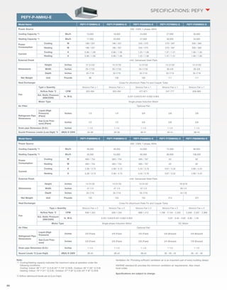
![Model Name PEFY-AF1200CFM PEFY-AF1200CFMR
Power Source 208 / 230V, 1 Phase, 60Hz
Cooling Capacity Btu/h *1 112,000 112,000
Heating Capacity Btu/h *1 61,400 61,400
Reheat Capacity Btu/h - 24, 200
Power Consumption
Cooling W 660 / 780
Heating W 660 / 780
Current
Cooling A 3.19 / 3.45
Heating A 660 / 670
External Finish Munsell No. 6.4Y 8.9 / 0.4
Dimensions
Height Inches 18-9/16
Width Inches 49-1/4
Depth Inches 55-1/8
Net Weight Unit Pounds 287 309
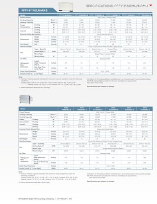
Heat Exchanger Cross Fin (Aluminum Plate Fin and Copper Tube)
Fan
Type x quantity Sirocco Fan x 2
Airflow Rate *2 CFM 1,200
External Static
Pressure
In.WG
0.40-0.60-0.88 (208V) 0.28-0.48-0.80 (208V)
0.64-0.80-1.04 (230V) 0.52-0.72-0.96 (230V)
Motor Type Single-phase Induction Motor
Air Filter Field Supply
Main Coil
Refrigerant Pipe
Dimensions
Liquid (High Pres-sure)
(Flare)
Inches 3/8
Gas (Low Pressure)
(Flare) Inches 7/8
Reheat Coil
Refrigerant Pipe
Dimensions
Liquid (High Pres-sure)
(Flare)
Inches - 7/8
Gas (Low Pressure)
(Flare) Inches - 3/8
Drain Pipe Dimension (O.D.) Inches 1-1/4 x 2
Sound Pressure
Level *3
Low-Mid-High dB(A)
36-38-41 (208V)
39-41-43 (230V)
Operating Tempera-ture
Range
Cooling 50° F WB to 95° F WB (109° F DB)
(10° C WB to 35° C WB [43° C DB])
Heating -4° F WB +60° F WB
(-20° C WB +16° C WB)
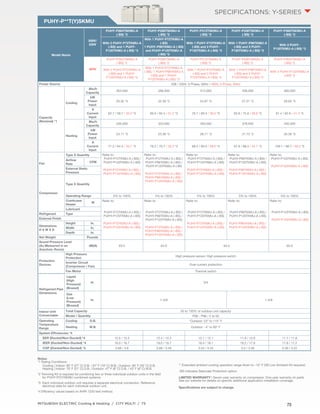
Connectable Outdoor Unit PUHY-P120TKMU (-BS), PUHY-P120YKMU (-BS)
PUHY-P120TJMU (-BS), PUHY-P120YJMU (-BS)
PURY-P120TKMU (-BS), PURY-P120YKMU (-BS)
PURY-P120TJMU (-BS), PURY-P120YJMU (-BS)
PEFY-AF
SPECIFICATIONS: DEDICATED OUTDOOR
AIR SYSTEMS
Note:
*1 Cooling/Heating Capacity indicates the maximum value at operation under the
following conditions:
Cooling | Entering Indoor Unit: 87° F (31° C) D.B. / 80° F (27° C) W.B.; Outdoor Unit: 87° F
(31° C) D.B.
Heating | Entering Indoor Unit: 32° F (0° C) D.B.; Outdoor Unit: 32° F (0° C) D.B. / 28° F (-2°
C) W.B.
*2 Airflow rate/sound pressure levels are at Low-Mid-Hi.
Ventilation Air: Providing sufficient ventilation air is an important part of very building design
ASHRAE Standard 62 provides the minimum air requirements. Also check local codes.
Specifications are subject to change.](https://image.slidesharecdn.com/hvac-refrigerated-flow-zone-system-catalog-141017130733-conversion-gate01/85/Refrigerant-Flow-Zone-Heating-and-Cooling-System-Catalog-94-320.jpg)


![Samsung dvm s catalogue [60 hz.]](https://cdn.slidesharecdn.com/ss_thumbnails/samsungdvmscatalogs60hz-170226044330-thumbnail.jpg?width=640&height=640&fit=bounds)