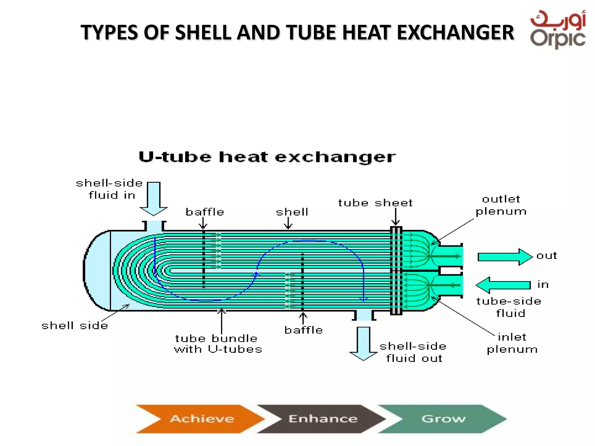
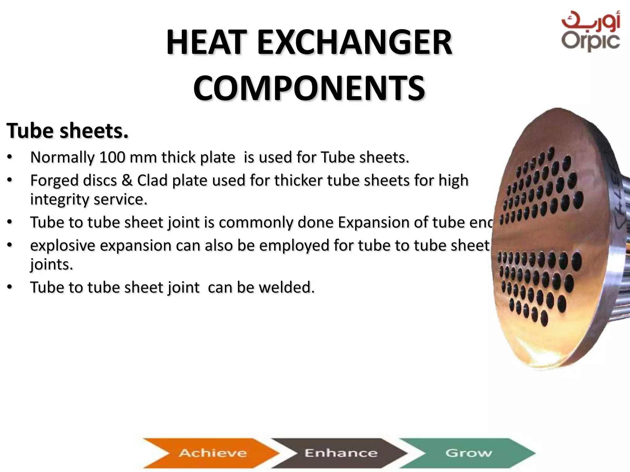
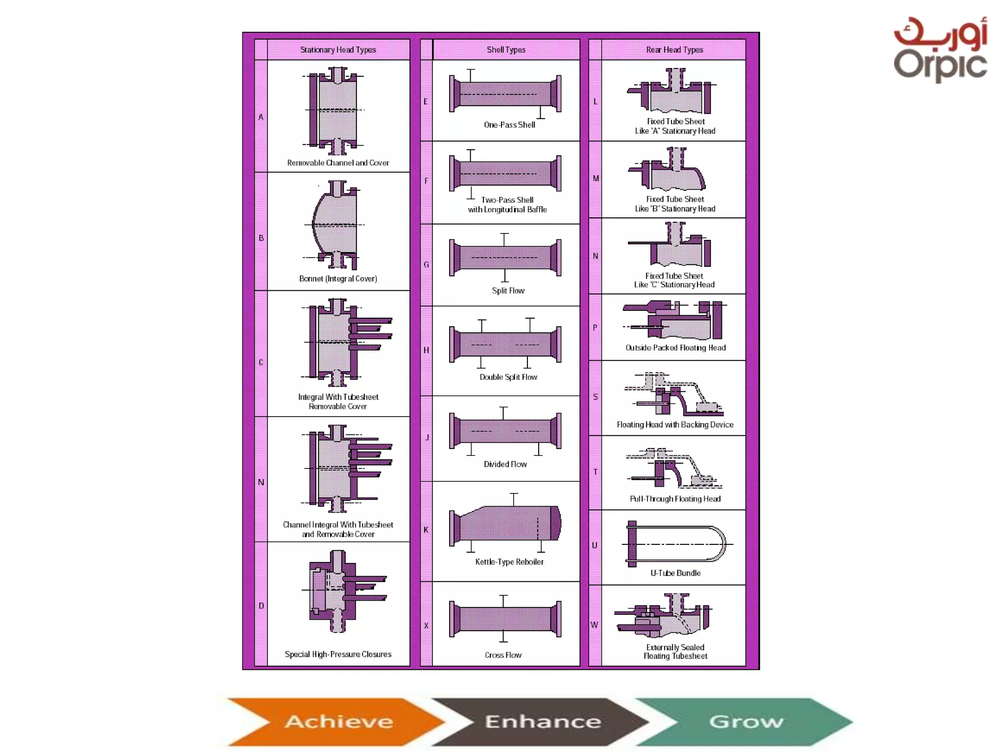
HEAT EXCHANGERS
Presentation on Heat Exchangers
Heat Exchanger is ……
A device that is used to transfer thermal energy
(enthalpy) between two or more fluids, between a solid
surface and a fluid, or between solid particulates and
a fluid,
at different temperatures
and in thermal contact.
Presentation on Heat Exchangers
HEAT EXCHANGERS FUNCTIONS
• Heating / Cooling / Evaporation
• Cooling of lubricants
• Heating of boiler feed water
• Condensing steam for re-use
• Preheating
Presentation on Heat Exchangers
CLASSIFICATION
Presentation on Heat Exchangers
Classification on the basis of
Direction of Flow
HEAT EXCHANGERS
COUNTERFLOW PARALLEL FLOW CROSS FLOW HYBRID FLOW
Presentation on Heat Exchangers
CLASSIFICATION
On the basis of Fluid Type:
• Gas to Gas
• Gas to Liquid (evaporator, condenser)
• Liquid to liquid
On the basis of Flow Pattern:
• Single Pass
• Multi Pass
On the basis of Shape & Geometry:
Shell & Tube
Double Pipe
Plate type
Presentation on Heat Exchangers
DIVISION OF TUBULAR TYPE HEAT
EXCHANGERS
TUBULAR
SHELL
&TUBE
FURNACES TUBE IN PLATE ELEC HEATED
AIR
COOLED
Presentation on Heat Exchangers
Selection
Presentation on Heat Exchangers
 High/low pressure limits
 Thermal performance
 Temperature ranges
 Product mix (liquid/liquid, particulates or
high-solids liquid)
 Pressure drops across the exchanger
 Fluid flow capacity
 Cost
 Cleanability, maintenance and repair
 Materials required for construction
 Ability and ease of future expansion
WORKING OF TUBULAR TYPE EXCHANGER
Presentation on Heat Exchangers
SHELL AND TUBE HEAT EXCHANGER
• A Shell and tube heat
exchanger is the most
common type of heat
exchanger used in oil
refineries and other large
chemical process plants. As
its name implies, this type
of heat exchanger consists
of a shell (a large vessel)
with a bundle of tubes
inside it.
Presentation on Heat Exchangers
SHELL AND TUBE HEAT EXCHANGER
Presentation on Heat Exchangers
TYPES OF SHELL AND TUBE HEAT EXCHANGER
Presentation on Heat Exchangers
TYPES OF SHELL AND TUBE HEAT EXCHANGER
Presentation on Heat Exchangers
TYPES OF SHELL AND TUBE HEAT EXCHANGER
Presentation on Heat Exchangers
TUBE LAYOUT PATTERNS
 TRIANGULAR
 Accommodates more tubes
 Produces high Turbulence
 Limited to Clean Shell side Services
 SQUARE
 Where cleaning is required
 It produces low turbulence
 Accommodates low No of tubes
Presentation on Heat Exchangers
HEAT EXCHANGER
COMPONENTS
Channel partition plates.
• For exchangers with multiple tube passes,
the channels are fitted with flat metal plates
which divide the head into separate
compartments.
Shell baffles. -Use
• Shell cross baffles support the tubes at
intervals
– Prevent sag and vibration.
– Force the shell side fluid back and forth
across the bundle.
• Type:Segmental single cut baffles are the
most common
Presentation on Heat Exchangers
Shell baffles. -Type
• Longitudinal Flow Baffles (used in a two-
pass shell)
• Impingement Baffles (used for
protecting bundle when entrance
velocity is high)
• Orifice Baffles
• Single segmental
• Double segmental
• Disk and doughnut baffles
HEAT EXCHANGER
COMPONENTS
Tie rods.
• Tie rods are circular metal rods screwed into the stationary tube sheet and
secured at the farthest baffle by lock nuts.
• Tie rods and spacers hold the tube bundle together in the correct position.
• The No of tie rods depends on shell diameter as specified by TEMA.
Shell barrel.
• TEMA specifies minimum barrel thicknesses depending on diameter,
material and class.
• Most barrels larger than 450 mm internal diameter are fabricated from
rolled and welded plate.
• The shell barrel must be straight and true as a tightly fitting tube bundle
must be inserted.
Presentation on Heat Exchangers
C-Type
Front Head Type
A-Type B-Type
Presentation on Heat Exchangers
Shell type
E-Type F-Type
J-Type K-Type
Presentation on Heat Exchangers
Rear End Head Types
M-Type
Fixed Tubesheet
S-Type
Floating Head
T-Type
Pull-Through
Floating Head
Presentation on Heat Exchangers
1-Channel cover
2-Stationary head channel
3-Channel flange
4-Pass partition plate
5- Tube sheet
6-Shell flange
7-Tube
8-Shell
9-Baffles
10-Floating head backing device
11-Floating tube sheet
12-Floating head
13-Floating head flange
14-Stationary head bonnet
15-Heat exchanger support
16-Shell expansion joint
Components
Shell
fluid in
Tube
fluid out
Shell-fluid
nozzle
Tube
fluid in
Shell
fluid out
Presentation on Heat Exchangers
HEAT EXCHANGER
COMPONENTS
Tube sheets.
• Normally 100 mm thick plate is used for Tube sheets.
• Forged discs & Clad plate used for thicker tube sheets for high
integrity service.
• Tube to tube sheet joint is commonly done Expansion of tube ends.
• explosive expansion can also be employed for tube to tube sheet
joints.
• Tube to tube sheet joint can be welded.
Presentation on Heat Exchangers
Shell And Tube Heat Exchanger Application
• Cooling of hydraulic fluid.
• Cooling of engine oils.
• Cool or heat swimming pool water or charged
air.
Presentation on Heat Exchangers
Double Pipe Heat Exchanger
• It is also known as concentric tube heat exchanger
• In this heat exchanger the fluid to be cooled or heated
passes through the tube 2(green) and the other fluid is
passed through tube 1 (red)to absorb or release the heat.
• Advantages: Cheap for both design and maintenance.
• Disadvantages: Low efficiency and requires large space.
Presentation on Heat Exchangers
Double Pipe Heat Exchanger
Presentation on Heat Exchangers
Double pipe heat exchanger
• Heat recovery
• Pre-heating
• Effluent cooling
Presentation on Heat Exchangers
Air Cooled Heat Exchanger
• “An Air Cooled Heat Exchanger (or Air Fin
Cooler) is a device for rejecting heat from a
fluid directly to ambient air”
• The obvious advantage of an AFC is that it
does not require water, which means that
plants requiring large cooling capacities need
not be located near a supply of cooling water.
Presentation on Heat Exchangers
Air Cooled Heat Exchanger
Advantages:
• Air Piping system is not required
• Larger limit of air supply volume
• No fouling/scaling outside the tubes
• More economical
• Easy maintenance
• No possibility of contamination of or from process flow
• In case of electrical malfunction, 30%- 40% cooling is
done by Natural Draft
Presentation on Heat Exchangers
Air Cooled Heat Exchanger
Disadvantages:
• Cooling level is limited by ambient temperature
• More electrical equipment needed
• Higher Initial Costs
• Leakage is more dangerous (Fire hazard)
• More sensitive to rains
Presentation on Heat Exchangers
Air Cooled Heat Exchanger
Presentation on Heat Exchangers
Air Cooled Heat Exchanger-Component
An AFC consists of the following components:
• One or more bundles of heat transfer surface.
• An air-moving device, such as a fan or stack.
• Unless it is natural draft, a driver and power
transmission to mechanically rotate the fan.
Presentation on Heat Exchangers
Air Cooled Heat Exchanger-Component
• A support structure high enough to allow air to
enter beneath the AFC at a reasonable rate.
• Optional header and fan maintenance walkways
with ladders.
• Optional louvers for process outlet temperature
control.
• Optional variable pitch fan hub for temperature
control and power savings.
Presentation on Heat Exchangers
TEMA
Tubular Exchanger Manufacturers Association
Presentation on Heat Exchangers
• It is composed of multiple, thin, slightly separated plates that have
very large surface areas and fluid flow passages for heat transfer.
• The plates are often spaced by rubber sealing gaskets which are
cemented into a section around the edge of the plates. The plates
are pressed to form troughs at right angles to the direction of flow
of the liquid which runs through the channels in the heat exchanger.
These troughs are arranged so that they interlink with the other
plates which forms the channel with gaps of 1.3–1.5 mm between
the plates.
Presentation on Heat Exchangers
Plate Heat Exchanger
PLATE TYPE HEAT EXCHANGER
Presentation on Heat Exchangers
PLATE TYPE HEAT EXCHANGER
Presentation on Heat Exchangers
WORKING OF PLATE TYPE HEAT
EXCHANGER
Presentation on Heat Exchangers
COMPARISON OF HEAT EXCHANGERS
PLATE TYPE
• Corrugated plates mounted
and fasten together.
• Used for low temperature
and pressure.
• Larger surface area.
• Handles Non contaminated
fluids.
• Cooling media can be any
non corrosive fluid
TUBULAR TYPE
• SS or CS Tubes in side a SS or
CS Shell or other tubular
arrangement.
• Used for high temperature
and pressure.
• Low surface area.
• Suitable for handling
contaminated fluids.
• Cooling media can be any
fluid
Presentation on Heat Exchangers
Spiral Heat Exchanger
• A spiral heat exchanger (SHE), may refer to
a helical (coiled) tube configuration
• Efficient use of space.
• They can be easily cleaned.
• A Spiral Heat Exchangers (or SHE) is a coiled tube
arrangement, with two channels coiled one around
the another. These two channels operate in a
counter-flow arrangement, offering excellent turn
down ratios, while optimizing flow patterns which in
turn, enhance heat transfer.
Presentation on Heat Exchangers
Spiral Heat Exchanger
Presentation on Heat Exchangers
Spiral Heat Exchanger Application
• Pasteurization
• Recuperates (Exhaust and Air Handling Systems)
• Sludge Treatment (Thermal depolymerisation)
Presentation on Heat Exchangers
Special Type
• Packinox:
• Welded plat type
• Use for clean service
• Give high heat transfer
co-efficient
• Required special
attention
• Costly
• Texas tower
• Vertical shell and tube
heat exchanger
Presentation on Heat Exchangers
MAINTENANCE OF HEAT EXCHANGERS
Five major steps are involved in cleaning a
small exchanger in shop:
1) Disassembly
2) Cleaning, Testing for Leaks
3) inspection & repair
4) Reassembly
5) Final Testing
Presentation on Heat Exchangers
MAINTENANCE OF HEAT EXCHANGERS
Testing for Leaky Tubes:
• For detection of leaky tubes, exchanger is isolated & head cover is
removed to expose the tube sheet.
• Generally, shell is filled with water & test pressure is applied for a
certain time. In case of leakage, pressure drops & water comes out
through leaky tubes.
• Plugs are inserted in leaky tubes and welded.
• Plugging of 10% tubes is allowable.
• After plugging, exchanger is again pressure tested.
Presentation on Heat Exchangers
CLEANING OF EXCHANGER
• Mechanical Cleaning
– Shell side (water jetting / Manual Scrapping)
– Tube side (Water jetting)
• Scale Cutters / brushes
• Lances for tube cleaning
• Chemical Cleaning
– Carbon Tetra Chloride is used to dissolve scales
which can not be scrapped Mechanically
Presentation on Heat Exchangers
PROBLEMS IN HEAT EXCHANGERS
1.FOULING
“ Formation of scale on the heat transfer surfaces in the heat
exchanger is called FOULLING “
EFFECTS:
• Reduction in heat transfer.
• Reduction in volume flow.
• Decrease in efficiency of exchanger.
• Increase in differential pressure
SOLUTION:
• Chemical injection
• Exchanger cleaning- Hydrojetting, Steaming, chemical washing
Presentation on Heat Exchangers
PROBLEMS IN HEAT EXCHANGERS
2.Tube Leaks
EFFECTS:
• Reduction in heat transfer.
• Contamination in product
• Decrease in efficiency of exchanger.
SOLUTION:
• Tube replacement or Tube plugging
Presentation on Heat Exchangers
PROBLEMS IN HEAT EXCHANGERS
3.Corrosion
EFFECTS:
• Thickness Reduction of tubes and shell
• Tube choking
• Increase in differential pressure
• Decrease in efficiency of exchanger.
SOLUTION:
• Tube replacement
• Surface coating
Presentation on Heat Exchangers
PROBLEMS IN HEAT EXCHANGERS
4.Thermal Shock
EFFECTS:
• Tube Sheet flange leak
• Tube leak
• Damage in expansion bellows
SOLUTION:
• Follow up SOPs
Presentation on Heat Exchangers
TESTING METHODS
• HYDROTEST
– Water is used as testing media.
– Test pressure is 1.5 times design pressure.
• PNEUMATIC
– Air is used as a testing media.
– Test pressure is 1.25 times design pressure.
• GAS TEST
– Any gas other then Air is used e.g. Nitrogen.
Presentation on Heat Exchangers
Things to be monitored….
• Inlet and outlet temperature of hot and cold
fluid
• Fluid velocity
• Approach temperature
• LMTD (log mean temperature deference)
• Differential Pressure
• External leakages
• Visual inspection for uneven expansion and
abnormal sound
Presentation on Heat Exchangers
THANKS
Presentation on Heat Exchangers

HEAT_EXCHANGER_Final.ppt

  • 1.
  • 2.
    Heat Exchanger is…… A device that is used to transfer thermal energy (enthalpy) between two or more fluids, between a solid surface and a fluid, or between solid particulates and a fluid, at different temperatures and in thermal contact. Presentation on Heat Exchangers
  • 3.
    HEAT EXCHANGERS FUNCTIONS •Heating / Cooling / Evaporation • Cooling of lubricants • Heating of boiler feed water • Condensing steam for re-use • Preheating Presentation on Heat Exchangers
  • 4.
  • 5.
    Classification on thebasis of Direction of Flow HEAT EXCHANGERS COUNTERFLOW PARALLEL FLOW CROSS FLOW HYBRID FLOW Presentation on Heat Exchangers
  • 6.
    CLASSIFICATION On the basisof Fluid Type: • Gas to Gas • Gas to Liquid (evaporator, condenser) • Liquid to liquid On the basis of Flow Pattern: • Single Pass • Multi Pass On the basis of Shape & Geometry: Shell & Tube Double Pipe Plate type Presentation on Heat Exchangers
  • 7.
    DIVISION OF TUBULARTYPE HEAT EXCHANGERS TUBULAR SHELL &TUBE FURNACES TUBE IN PLATE ELEC HEATED AIR COOLED Presentation on Heat Exchangers
  • 8.
    Selection Presentation on HeatExchangers  High/low pressure limits  Thermal performance  Temperature ranges  Product mix (liquid/liquid, particulates or high-solids liquid)  Pressure drops across the exchanger  Fluid flow capacity  Cost  Cleanability, maintenance and repair  Materials required for construction  Ability and ease of future expansion
  • 9.
    WORKING OF TUBULARTYPE EXCHANGER Presentation on Heat Exchangers
  • 10.
    SHELL AND TUBEHEAT EXCHANGER • A Shell and tube heat exchanger is the most common type of heat exchanger used in oil refineries and other large chemical process plants. As its name implies, this type of heat exchanger consists of a shell (a large vessel) with a bundle of tubes inside it. Presentation on Heat Exchangers
  • 11.
    SHELL AND TUBEHEAT EXCHANGER Presentation on Heat Exchangers
  • 12.
    TYPES OF SHELLAND TUBE HEAT EXCHANGER Presentation on Heat Exchangers
  • 13.
    TYPES OF SHELLAND TUBE HEAT EXCHANGER Presentation on Heat Exchangers
  • 14.
    TYPES OF SHELLAND TUBE HEAT EXCHANGER Presentation on Heat Exchangers
  • 15.
    TUBE LAYOUT PATTERNS TRIANGULAR  Accommodates more tubes  Produces high Turbulence  Limited to Clean Shell side Services  SQUARE  Where cleaning is required  It produces low turbulence  Accommodates low No of tubes Presentation on Heat Exchangers
  • 16.
    HEAT EXCHANGER COMPONENTS Channel partitionplates. • For exchangers with multiple tube passes, the channels are fitted with flat metal plates which divide the head into separate compartments. Shell baffles. -Use • Shell cross baffles support the tubes at intervals – Prevent sag and vibration. – Force the shell side fluid back and forth across the bundle. • Type:Segmental single cut baffles are the most common Presentation on Heat Exchangers
  • 17.
    Presentation on HeatExchangers Shell baffles. -Type • Longitudinal Flow Baffles (used in a two- pass shell) • Impingement Baffles (used for protecting bundle when entrance velocity is high) • Orifice Baffles • Single segmental • Double segmental • Disk and doughnut baffles
  • 18.
    HEAT EXCHANGER COMPONENTS Tie rods. •Tie rods are circular metal rods screwed into the stationary tube sheet and secured at the farthest baffle by lock nuts. • Tie rods and spacers hold the tube bundle together in the correct position. • The No of tie rods depends on shell diameter as specified by TEMA. Shell barrel. • TEMA specifies minimum barrel thicknesses depending on diameter, material and class. • Most barrels larger than 450 mm internal diameter are fabricated from rolled and welded plate. • The shell barrel must be straight and true as a tightly fitting tube bundle must be inserted. Presentation on Heat Exchangers
  • 19.
    C-Type Front Head Type A-TypeB-Type Presentation on Heat Exchangers
  • 20.
    Shell type E-Type F-Type J-TypeK-Type Presentation on Heat Exchangers
  • 21.
    Rear End HeadTypes M-Type Fixed Tubesheet S-Type Floating Head T-Type Pull-Through Floating Head Presentation on Heat Exchangers
  • 22.
    1-Channel cover 2-Stationary headchannel 3-Channel flange 4-Pass partition plate 5- Tube sheet 6-Shell flange 7-Tube 8-Shell 9-Baffles 10-Floating head backing device 11-Floating tube sheet 12-Floating head 13-Floating head flange 14-Stationary head bonnet 15-Heat exchanger support 16-Shell expansion joint Components Shell fluid in Tube fluid out Shell-fluid nozzle Tube fluid in Shell fluid out Presentation on Heat Exchangers
  • 23.
    HEAT EXCHANGER COMPONENTS Tube sheets. •Normally 100 mm thick plate is used for Tube sheets. • Forged discs & Clad plate used for thicker tube sheets for high integrity service. • Tube to tube sheet joint is commonly done Expansion of tube ends. • explosive expansion can also be employed for tube to tube sheet joints. • Tube to tube sheet joint can be welded. Presentation on Heat Exchangers
  • 24.
    Shell And TubeHeat Exchanger Application • Cooling of hydraulic fluid. • Cooling of engine oils. • Cool or heat swimming pool water or charged air. Presentation on Heat Exchangers
  • 25.
    Double Pipe HeatExchanger • It is also known as concentric tube heat exchanger • In this heat exchanger the fluid to be cooled or heated passes through the tube 2(green) and the other fluid is passed through tube 1 (red)to absorb or release the heat. • Advantages: Cheap for both design and maintenance. • Disadvantages: Low efficiency and requires large space. Presentation on Heat Exchangers
  • 26.
    Double Pipe HeatExchanger Presentation on Heat Exchangers
  • 27.
    Double pipe heatexchanger • Heat recovery • Pre-heating • Effluent cooling Presentation on Heat Exchangers
  • 28.
    Air Cooled HeatExchanger • “An Air Cooled Heat Exchanger (or Air Fin Cooler) is a device for rejecting heat from a fluid directly to ambient air” • The obvious advantage of an AFC is that it does not require water, which means that plants requiring large cooling capacities need not be located near a supply of cooling water. Presentation on Heat Exchangers
  • 29.
    Air Cooled HeatExchanger Advantages: • Air Piping system is not required • Larger limit of air supply volume • No fouling/scaling outside the tubes • More economical • Easy maintenance • No possibility of contamination of or from process flow • In case of electrical malfunction, 30%- 40% cooling is done by Natural Draft Presentation on Heat Exchangers
  • 30.
    Air Cooled HeatExchanger Disadvantages: • Cooling level is limited by ambient temperature • More electrical equipment needed • Higher Initial Costs • Leakage is more dangerous (Fire hazard) • More sensitive to rains Presentation on Heat Exchangers
  • 31.
    Air Cooled HeatExchanger Presentation on Heat Exchangers
  • 32.
    Air Cooled HeatExchanger-Component An AFC consists of the following components: • One or more bundles of heat transfer surface. • An air-moving device, such as a fan or stack. • Unless it is natural draft, a driver and power transmission to mechanically rotate the fan. Presentation on Heat Exchangers
  • 33.
    Air Cooled HeatExchanger-Component • A support structure high enough to allow air to enter beneath the AFC at a reasonable rate. • Optional header and fan maintenance walkways with ladders. • Optional louvers for process outlet temperature control. • Optional variable pitch fan hub for temperature control and power savings. Presentation on Heat Exchangers
  • 34.
    TEMA Tubular Exchanger ManufacturersAssociation Presentation on Heat Exchangers
  • 35.
  • 36.
    • It iscomposed of multiple, thin, slightly separated plates that have very large surface areas and fluid flow passages for heat transfer. • The plates are often spaced by rubber sealing gaskets which are cemented into a section around the edge of the plates. The plates are pressed to form troughs at right angles to the direction of flow of the liquid which runs through the channels in the heat exchanger. These troughs are arranged so that they interlink with the other plates which forms the channel with gaps of 1.3–1.5 mm between the plates. Presentation on Heat Exchangers Plate Heat Exchanger
  • 37.
    PLATE TYPE HEATEXCHANGER Presentation on Heat Exchangers
  • 38.
    PLATE TYPE HEATEXCHANGER Presentation on Heat Exchangers
  • 39.
    WORKING OF PLATETYPE HEAT EXCHANGER Presentation on Heat Exchangers
  • 40.
    COMPARISON OF HEATEXCHANGERS PLATE TYPE • Corrugated plates mounted and fasten together. • Used for low temperature and pressure. • Larger surface area. • Handles Non contaminated fluids. • Cooling media can be any non corrosive fluid TUBULAR TYPE • SS or CS Tubes in side a SS or CS Shell or other tubular arrangement. • Used for high temperature and pressure. • Low surface area. • Suitable for handling contaminated fluids. • Cooling media can be any fluid Presentation on Heat Exchangers
  • 41.
    Spiral Heat Exchanger •A spiral heat exchanger (SHE), may refer to a helical (coiled) tube configuration • Efficient use of space. • They can be easily cleaned. • A Spiral Heat Exchangers (or SHE) is a coiled tube arrangement, with two channels coiled one around the another. These two channels operate in a counter-flow arrangement, offering excellent turn down ratios, while optimizing flow patterns which in turn, enhance heat transfer. Presentation on Heat Exchangers
  • 42.
  • 43.
    Spiral Heat ExchangerApplication • Pasteurization • Recuperates (Exhaust and Air Handling Systems) • Sludge Treatment (Thermal depolymerisation) Presentation on Heat Exchangers
  • 44.
    Special Type • Packinox: •Welded plat type • Use for clean service • Give high heat transfer co-efficient • Required special attention • Costly • Texas tower • Vertical shell and tube heat exchanger Presentation on Heat Exchangers
  • 45.
    MAINTENANCE OF HEATEXCHANGERS Five major steps are involved in cleaning a small exchanger in shop: 1) Disassembly 2) Cleaning, Testing for Leaks 3) inspection & repair 4) Reassembly 5) Final Testing Presentation on Heat Exchangers
  • 46.
    MAINTENANCE OF HEATEXCHANGERS Testing for Leaky Tubes: • For detection of leaky tubes, exchanger is isolated & head cover is removed to expose the tube sheet. • Generally, shell is filled with water & test pressure is applied for a certain time. In case of leakage, pressure drops & water comes out through leaky tubes. • Plugs are inserted in leaky tubes and welded. • Plugging of 10% tubes is allowable. • After plugging, exchanger is again pressure tested. Presentation on Heat Exchangers
  • 47.
    CLEANING OF EXCHANGER •Mechanical Cleaning – Shell side (water jetting / Manual Scrapping) – Tube side (Water jetting) • Scale Cutters / brushes • Lances for tube cleaning • Chemical Cleaning – Carbon Tetra Chloride is used to dissolve scales which can not be scrapped Mechanically Presentation on Heat Exchangers
  • 48.
    PROBLEMS IN HEATEXCHANGERS 1.FOULING “ Formation of scale on the heat transfer surfaces in the heat exchanger is called FOULLING “ EFFECTS: • Reduction in heat transfer. • Reduction in volume flow. • Decrease in efficiency of exchanger. • Increase in differential pressure SOLUTION: • Chemical injection • Exchanger cleaning- Hydrojetting, Steaming, chemical washing Presentation on Heat Exchangers
  • 49.
    PROBLEMS IN HEATEXCHANGERS 2.Tube Leaks EFFECTS: • Reduction in heat transfer. • Contamination in product • Decrease in efficiency of exchanger. SOLUTION: • Tube replacement or Tube plugging Presentation on Heat Exchangers
  • 50.
    PROBLEMS IN HEATEXCHANGERS 3.Corrosion EFFECTS: • Thickness Reduction of tubes and shell • Tube choking • Increase in differential pressure • Decrease in efficiency of exchanger. SOLUTION: • Tube replacement • Surface coating Presentation on Heat Exchangers
  • 51.
    PROBLEMS IN HEATEXCHANGERS 4.Thermal Shock EFFECTS: • Tube Sheet flange leak • Tube leak • Damage in expansion bellows SOLUTION: • Follow up SOPs Presentation on Heat Exchangers
  • 52.
    TESTING METHODS • HYDROTEST –Water is used as testing media. – Test pressure is 1.5 times design pressure. • PNEUMATIC – Air is used as a testing media. – Test pressure is 1.25 times design pressure. • GAS TEST – Any gas other then Air is used e.g. Nitrogen. Presentation on Heat Exchangers
  • 53.
    Things to bemonitored…. • Inlet and outlet temperature of hot and cold fluid • Fluid velocity • Approach temperature • LMTD (log mean temperature deference) • Differential Pressure • External leakages • Visual inspection for uneven expansion and abnormal sound Presentation on Heat Exchangers
  • 54.