Goals for Today
•Understand the basics of computer hardware
• Be able to describe how interrupts work
• Understand memory organization
3.
Purpose of anOS
• A program that controls the execution of
application programs
• An interface between the user or applications
and the hardware
• Mask the details of the hardware
• Allocates resources to programs
Assembler Programmer’s
Model ofthe Processor
• Registers
– Everything moves through the registers
– Arithmetic appears to occur in the registers
• Status Register
– Updated automatically by most instructions
– Status bits are the basis for jumps
• Instructions and data are in memory
– The assembler program deals with addresses
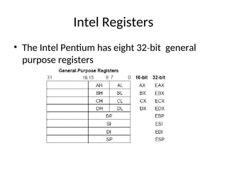
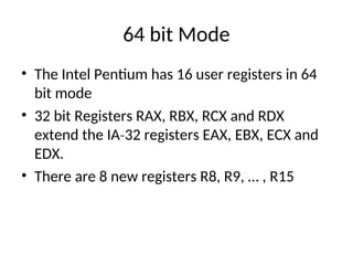
64 bit Mode
•The Intel Pentium has 16 user registers in 64
bit mode
• 32 bit Registers RAX, RBX, RCX and RDX
extend the IA 32 registers EAX, EBX, ECX and
‐
EDX.
• There are 8 new registers R8, R9, … , R15
8.
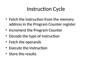
Instruction Cycle
• Fetchthe instruction from the memory
address in the Program Counter register
• Increment the Program Counter
• Decode the type of instruction
• Fetch the operands
• Execute the instruction
• Store the results
9.
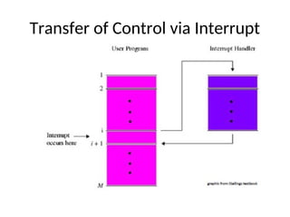
Interrupts and Exceptions
•An interrupt is a change in program defined
flow of execution.
• When an interrupt occurs, the hardware
executes the instructions at a specified
address instead of following the normal
program flow.
• The OS processes all interrupts.
• User programs are interrupted all the time.
Types of Interrupts
•External – Generated by an I/O device
• Internal – Exception within a program
• Program Generated – Used to transfer control
to the operating system
12.
External Interrupts
• I/Odevices tell the CPU that an I/O request
has completed by sending an interrupt signal
to the processor.
• I/O errors may also generate an interrupt.
• Most computers have a timer which interrupts
the CPU every so many milliseconds.
13.
Internal Interrupts
• Whenthe hardware detects that the program is doing
something wrong, it will usually generate an interrupt.
– Arithmetic error – Invalid Instruction
– Addressing error – Hardware malfunction
– Page fault – Debugging
• A Page Fault interrupt is not the result of a program
error, but it does require the operating system to get
control.
• Internal interrupts are sometimes called exceptions.
14.
Program Generated Interrupts
•Most computers have an instruction that
generates an internal interrupt.
• Program generated interrupts are a means for
user programs to call a function of the
operating system
• Some systems refer to these interrupts as a
SuperVisor Call or SVC
15.
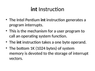
int Instruction
• TheIntel Pentium int instruction generates a
program interrupts.
• This is the mechanism for a user program to
call an operating system function.
• The int instruction takes a one byte operand.
• The bottom 1K (1024 bytes) of system
memory is devoted to the storage of interrupt
vectors.
16.
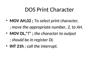
DOS Print Character
•MOV AH,02 ; To select print character,
; move the appropriate number, 2, to AH.
• MOV DL,"!" ; the character to output
; should be in register DL
• INT 21h ; call the interrupt.
17.
OS and HardwareResponse
• Hardware saves the current program counter and
status flags.
• Hardware loads new PC and flags.
• OS saves the registers
• OS determines cause of the interrupt
• OS does something (depends on the interrupts)
• OS restores the registers
• OS executes an interrupt return instruction to
load saved PC and flag values.
18.
Interrupt Service Routines
•When an interrupt occurs, execution starts in
an interrupt service routine (ISR) or interrupt
handler.
• The ISR is almost always in the OS.
• The interrupt service routine processes the
event or queues a program to process the
event.
• After an external interrupt, the service routine
will return to the program.
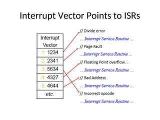
19.
ISR Entry Point
•It is possible for all interrupt service routines
to start at the same location. The software can
determine what kind of interrupt.
• The hardware can assist by using the interrupt
type as an index into a table of ISR addresses.
• Each interrupt may have a different ISR entry
point or classes of interrupts may have a
common entry point.
Multiple Interrupts
• Aninterrupt event can occur while the
processor is handling a previous interrupt.
• If the return address is always stored at a fixed
location, the occurrence of an interrupt while
handling a previous interrupt will overwrite
the previous return address.
• Most interrupt service routines start with
interrupts disabled. This prevents an interrupt
service routine from being interrupted.
22.
Interrupt Priorities
• Mostsystems prioritize the interrupts.
• If two interrupts happen at the same time, the
interrupt with the highest priority will be
serviced first.
23.
Masking Interrupts
• Someinterrupts can be temporarily disabled.
Most processors can disable external
interrupts.
• Most internal interrupts cannot be disabled.
• It is generally problematic to disable
interrupts for a lengthy period of time.
24.
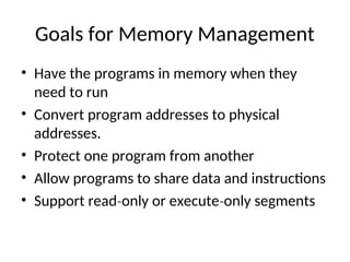
Goals for MemoryManagement
• Have the programs in memory when they
need to run
• Convert program addresses to physical
addresses.
• Protect one program from another
• Allow programs to share data and instructions
• Support read only or execute only segments
‐ ‐
25.
Sub Goals
• Fastaddress translation
• Simple for the p OS to allocate and release
memory.
• Minimize fragmentation
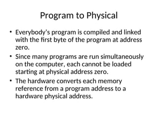
Program to Physical
•Everybody’s program is compiled and linked
with the first byte of the program at address
zero.
• Since many programs are run simultaneously
on the computer, each cannot be loaded
starting at physical address zero.
• The hardware converts each memory
reference from a program address to a
hardware physical address.
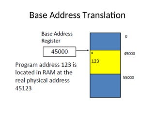
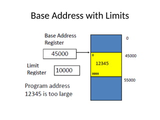
Base Address
• Programsare located in any convenient
contiguous part of memory.
• When a program is to execute, the base
register is loaded with the start address of the
program.
• The program effective address from each
memory reference is added to the value in the
base register to create the physical memory
location.
Limit Register
• Thelimit register contains the highest address
of the program.
• The memory system checks each memory
reference to make sure it is not greater than
the value in the limit register.
• An addressing exception interrupt occurs if
the address is too large.
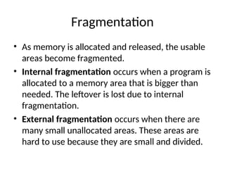
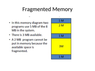
Fragmentation
• As memoryis allocated and released, the usable
areas become fragmented.
• Internal fragmentation occurs when a program is
allocated to a memory area that is bigger than
needed. The leftover is lost due to internal
fragmentation.
• External fragmentation occurs when there are
many small unallocated areas. These areas are
hard to use because they are small and divided.
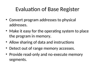
Evaluation of BaseRegister
• Convert program addresses to physical
addresses.
• Make it easy for the operating system to place
the program in memory.
• Allow sharing of data and instructions
• Detect out of range memory accesses.
• Provide read only and no execute memory
‐ ‐
segments.
36.
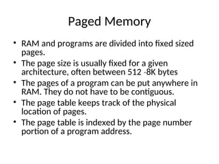
Paged Memory
• RAMand programs are divided into fixed sized
pages.
• The page size is usually fixed for a given
architecture, often between 512 8K bytes
‐
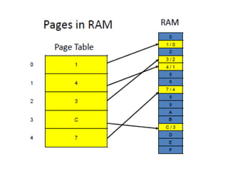
• The pages of a program can be put anywhere in
RAM. They do not have to be contiguous.
• The page table keeps track of the physical
location of pages.
• The page table is indexed by the page number
portion of a program address.
38.
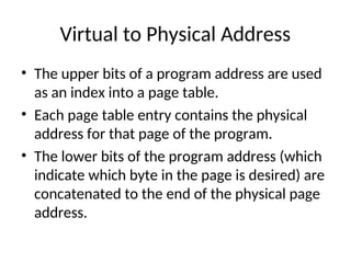
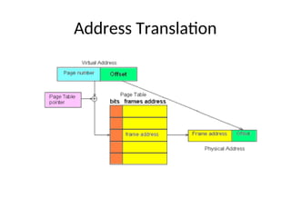
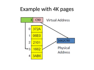
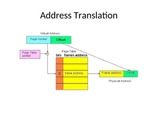
Virtual to PhysicalAddress
• The upper bits of a program address are used
as an index into a page table.
• Each page table entry contains the physical
address for that page of the program.
• The lower bits of the program address (which
indicate which byte in the page is desired) are
concatenated to the end of the physical page
address.
Big Programs
• Evenwhen using every byte of RAM, it is not
always possible to load all the programs users
would like.
• Frequently large parts of programs are never
executed. There are many features of
Microsoft Word® you have never used.
• More programs could fit in memory if only the
used portions were loaded into RAM.
42.
Virtual Memory
• VirtualMemory is an extension of paging.
• Only the pages that are being used are in
RAM.
• A copy of all pages of a program are on the
page file.
• If a program accesses an address in a page not
in RAM, the hardware creates a page fault
interrupt and the OS copies the desired page
into RAM.
43.
Virtual Memory Implementation
•Unused pages of a program do not need to be in
RAM to execute the program.
• A “resident” bit is added to the page table.
• Pages in RAM have the resident bit set.
• Pages not in RAM have the resident bit cleared.
• All pages are stored on disk.
• When a program references a page with the
resident bit clear, the hardware creates a page
fault interrupt.
Virtual Memory Hardwareand OS
• Virtual memory requires both hardware and
operating system support.
• When a page fault interrupt occurs, the OS
reads the desired page from disk into an
available page of RAM.
• The user’s page table is updated to point to
the newly loaded page.
• The program is placed back on the ready list
to be executed.
46.
Page Table Flags
•Each page table entry has flag bits
– Resident – set if the virtual address is in RAM and
clear otherwise.
– Used – set when the page is referenced.
– Dirty – set when the page is changed.
– No Execute – Instructions cannot be fetched from
this page.
• The Used and Dirty bits are set by the
hardware and cleared by the OS.
Locality of Reference
•Temporal locality a referenced location is
‐
likely to be referenced again.
• Spatial locality nearby locations are likely to
‐
be referenced soon.
49.
Evaluation of VirtualMemory
• Convert program addresses to physical
addresses.
• Make it easy for the operating system to place
the program in memory.
• Allow sharing of data and instructions
• Detect out of range memory accesses.
• Provide read only and no execute memory
‐ ‐
segments.
50.
Virtual Memory Advantages
•Allows you to fit many large programs into a
relatively small RAM.
• Only part of a program needs to be loaded
into memory.
• Eliminates the need to “fit” programs into
memory holes.
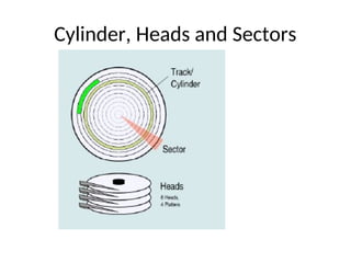
Terminology
• Sector orBlock – the smallest unit that can be
read or written. Often 512 bytes.
• Track – all blocks that form a ring on a disk
surface that can be read without moving the
head.
• Cylinder – all tracks on all surfaces, one on top
of another, that can be read without moving
the head.
53.
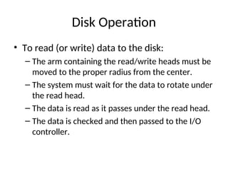
Disk Operation
• Toread (or write) data to the disk:
– The arm containing the read/write heads must be
moved to the proper radius from the center.
– The system must wait for the data to rotate under
the read head.
– The data is read as it passes under the read head.
– The data is checked and then passed to the I/O
controller.
54.
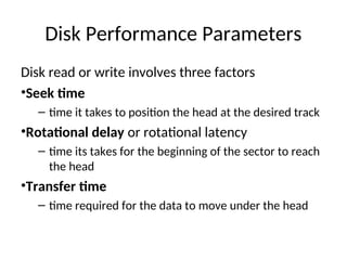
Disk Performance Parameters
Diskread or write involves three factors
•Seek time
– time it takes to position the head at the desired track
•Rotational delay or rotational latency
– time its takes for the beginning of the sector to reach
the head
•Transfer time
– time required for the data to move under the head