Downloaded 18 times
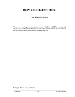
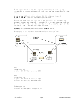
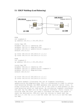
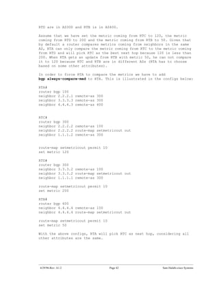
![6.0 Route Maps
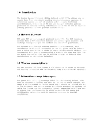
At this point I would like to introduce route maps because they will be
used heavily with BGP. In the BGP context, route map is a method used to
control and modify routing information. This is done by defining condi-
tions for redistributing routes from one routing protocol to another or
controlling routing information when injected in and out of BGP. The for-
mat of the route map follows:
route-map map-tag [[permit | deny] | [sequence-number]]
The map-tag is just a name you give to the route-map. Multiple instances
of the same route map (same name-tag) can be defined. The sequence number
is just an indication of the position a new route map is to have in the
list of route maps already configured with the same name.
For example, if I define two instances of the route map, let us call it
MYMAP, the first instance will have a sequence-number of 10, and the
second will have a sequence number of 20.
route-map MYMAP permit 10
(first set of conditions goes here.)
route-map MYMAP permit 20
(second set of conditions goes here.)
When applying route map MYMAP to incoming or outgoing routes, the first
set of conditions will be applied via instance 10. If the first set of
conditions is not met then we proceed to a higher instance of the route
map.
The conditions that we talked about are defined by the match and set
configuration commands. Each route map will consist of a list of match
and set configuration. The match will specify a match criteria and set
specifies a set action if the criteria enforced by the match command are
met.
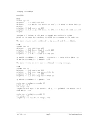
For example, I could define a route map that checks outgoing updates and
if there is a match for IP address 1.1.1.1 then the metric for that
update will be set to 5. The above can be illustrated by the following
commands:
match ip address 1.1.1.1
set metric 5
Now, if the match criteria are met and we have a permit then the routes
will be redistributed or controlled as specified by the set action and we
break out of the list.
If the match criteria are met and we have a deny then the route will not
be redistributed or controlled and we break out of the list.
4/29/96-Rev: A1.2 Page 13 Sam Halabi-cisco Systems](https://image.slidesharecdn.com/halabibgp4casestudiestutorial-13461527622183-phpapp01-120828062052-phpapp01/85/Halabi-Bgp4-Case-Studies-Tutorial-13-320.jpg)
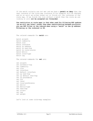
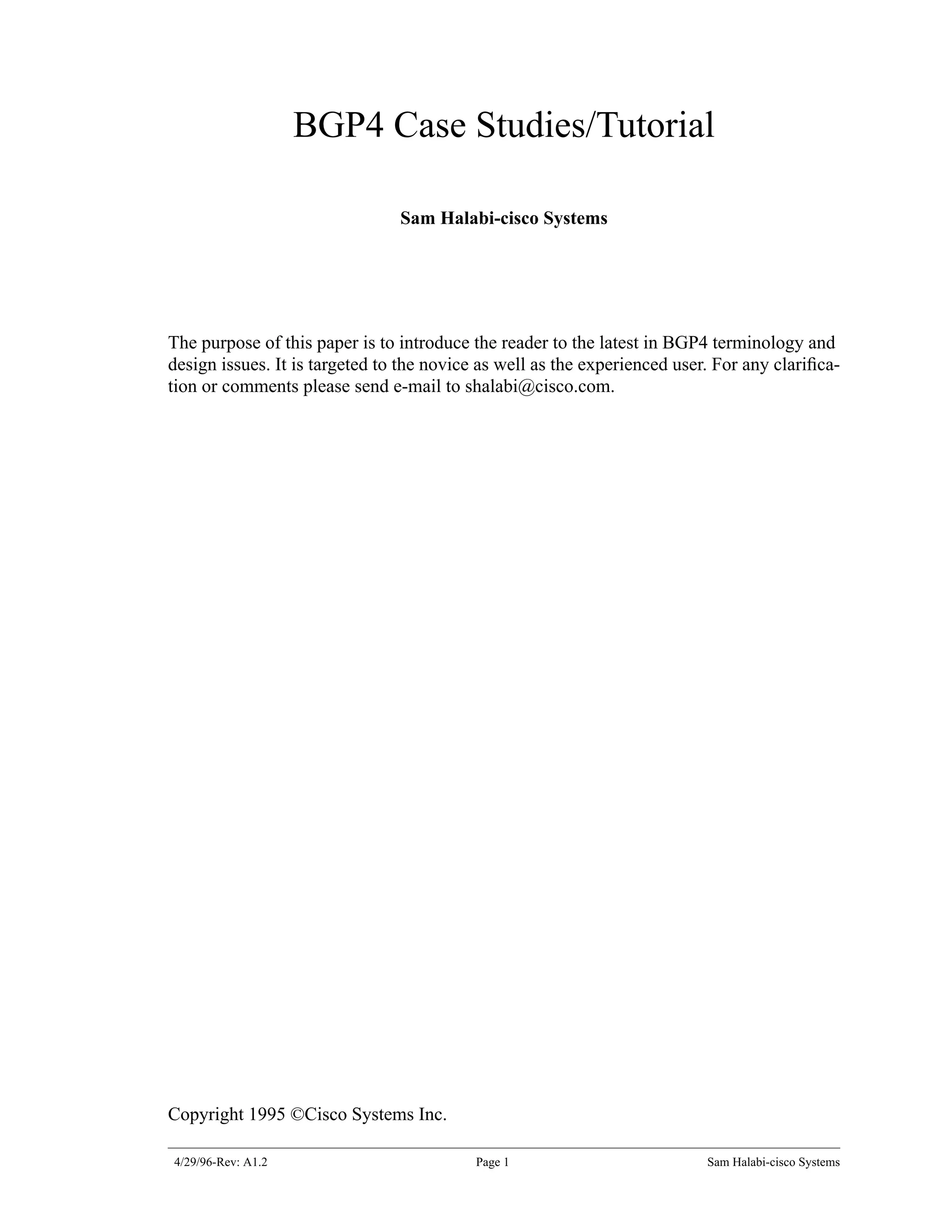
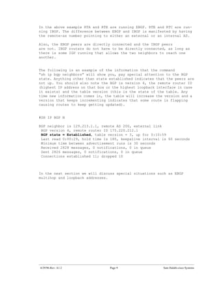
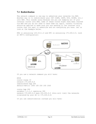
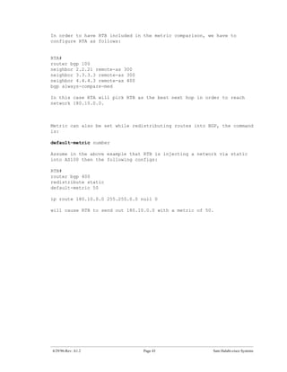
![7.0 Network command
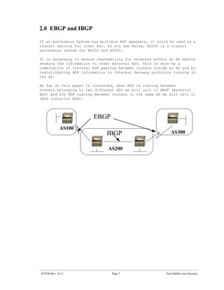
The format of the network command follows:
network network-number [mask network-mask]
The network command controls what networks are originated by this box.
This is a different concept from what you are used to configuring with
IGRP and RIP. With this command we are not trying to run BGP on a certain
interface, rather we are trying to indicate to BGP what networks it
should originate from this box. The mask portion is used because BGP4 can
handle subnetting and supernetting. A maximum of 200 entries of the
network command are accepted.
The network command will work if the network you are trying to advertise
is known to the router, whether connected, static or learned dynamically.
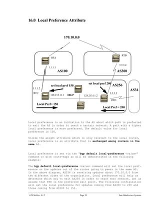
An example of the network command follows:
RTA#
router bgp 1
network 192.213.0.0 mask 255.255.0.0
ip route 192.213.0.0 255.255.0.0 null 0
The above example indicates that router A, will generate a network entry
for 192.213.0.0/16. The /16 indicates that we are using a supernet of the
class C address and we are advertizing the first two octets (the first 16
bits).
Note that we need the static route to get the router to generate
192.213.0.0 because the static route will put a matching entry in the
routing table.
4/29/96-Rev: A1.2 Page 17 Sam Halabi-cisco Systems](https://image.slidesharecdn.com/halabibgp4casestudiestutorial-13461527622183-phpapp01-120828062052-phpapp01/85/Halabi-Bgp4-Case-Studies-Tutorial-17-320.jpg)
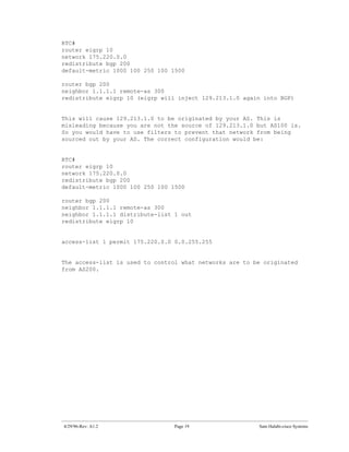
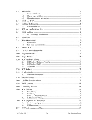
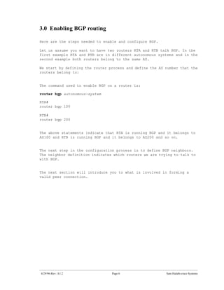
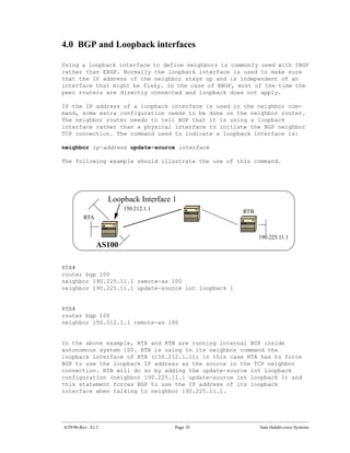
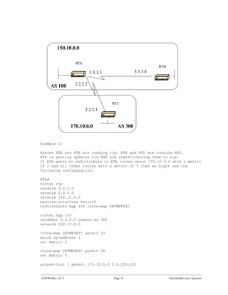
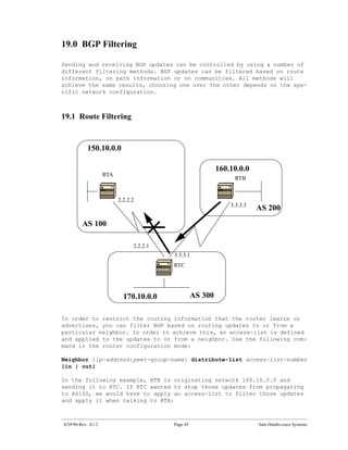
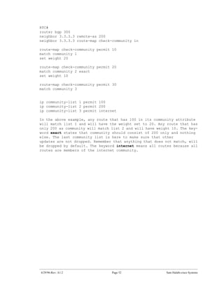
![18.0 Community Attribute
The community attribute is a way to group destinations in a certain com-
munity and apply routing decisions (accept, prefer, redistribute, etc.)
according to those communities.
We can use route maps to set the community attributes. The route map set
command has the following syntax:
set community community-number [additive]
A few predefined well known communities (community-number) are:
-no-export (Do not advertise to EBGP peers)
-no-advertise (Do not advertise this route to any peer)
-internet (Advertise this route to the internet community, any router
belongs to it)
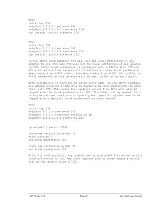
An example of route maps where community is set is:
route-map communitymap
match ip address 1
set community no-advertise
or
route-map setcommunity
match as-path 1
set community 200 additive
If the additive keyword is not set, 200 will replace any old community
that already exits; if we use the keyword additive then the 200 will be
added to the community.
Even if we set the community attribute, this attribute will not be sent
to neighbors by default.
In order to send the attribute to our neighbor we have to use the
following:
neighbor {ip-address|peer-group-name} send-community
Example:
RTA#
router bgp 100
neighbor 3.3.3.3 remote-as 300
neighbor 3.3.3.3 send-community
neighbor 3.3.3.3 route-map setcommunity out
4/29/96-Rev: A1.2 Page 44 Sam Halabi-cisco Systems](https://image.slidesharecdn.com/halabibgp4casestudiestutorial-13461527622183-phpapp01-120828062052-phpapp01/85/Halabi-Bgp4-Case-Studies-Tutorial-44-320.jpg)
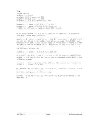
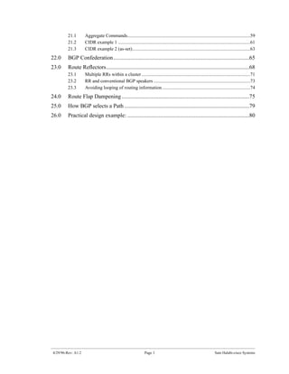
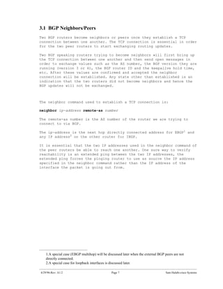
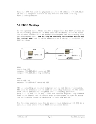
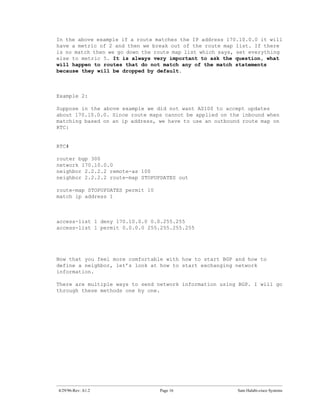
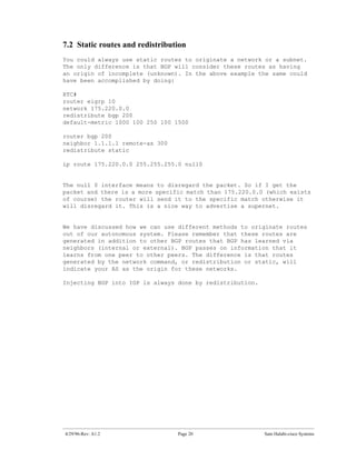
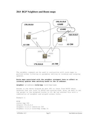
![19.2.1 AS-Regular Expression
A regular expression is a pattern to match against an input string.
By building a regular expression we specify a string that input must
match. In case of BGP we are specifying a string consisting of path
information that an input should match.
In the previous example we specified the string ^200$ and wanted path
information coming inside updates to match it in order to perform a
decision.
The regular expression is composed of the following:
A- Ranges:
A range is a sequence of characters contained within left and right
square brackets. ex: [abcd]
B- Atoms
An atom is a single character
. (Matches any single character)
^ (Matches the beginning of the input string)
$ (Matches the end of the input string)
character (Matches the character)
- (Matches a comma (,), left brace ({), right brace (}), the beginning
of the input string, the end of the input string, or a space.
C-Pieces
A piece is an atom followed by one of the symbols:
* (Matches 0 or more sequences of the atom)
+ (Matches 1 or more sequences of the atom)
? (Matches the atom or the null string)
D- Branch
A branch is a 0 or more concatenated pieces.
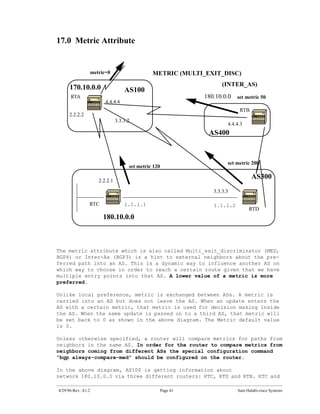
Examples of regular expressions follow:
a* any occurrence of the letter a, including none
a+ at least one occurrence of a should be present
ab?a this will match aa or aba
ex:
_100_(via AS100)
^100$ (origin AS100)
^100 .* (coming from AS100)
^$ (originated from this AS)
4/29/96-Rev: A1.2 Page 49 Sam Halabi-cisco Systems](https://image.slidesharecdn.com/halabibgp4casestudiestutorial-13461527622183-phpapp01-120828062052-phpapp01/85/Halabi-Bgp4-Case-Studies-Tutorial-49-320.jpg)
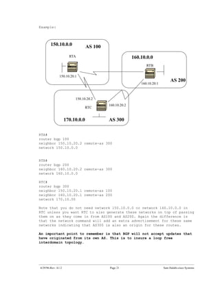
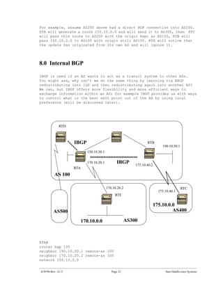
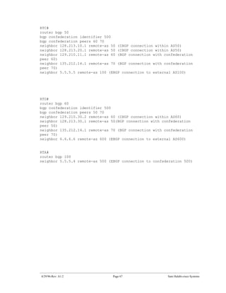
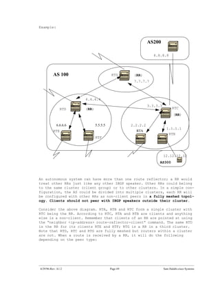
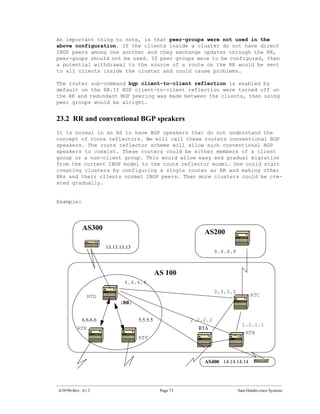
![The next two subjects, “confederation” and “route reflectors” are
designed for ISPs who would like to further control the explosion of IBGP
peering inside their autonomous systems.
22.0 BGP Confederation
BGP confederation is implemented in order to reduce the IBGP mesh inside
an AS. The trick is to divide an AS into multiple ASs and assign the
whole group to a single confederation. Each AS by itself will have IBGP
fully meshed and has connections to other ASs inside the confederation.
Even though these ASs will have EBGP peers to ASs within the confedera-
tion, they exchange routing as if they were using IBGP; next hop, metric
and local preference information are preserved. To the outside world, the
confederation (the group of ASs) will look as a single AS.
To configure a BGP confederation use the following:
bgp confederation identifier autonomous-system
The confederation identifier will be the AS number of the confederation
group. The group of ASs will look to the outside world as one AS with the
AS number being the confederation identifier.
Peering within the confederation between multiple ASs is done via the
following command:
bgp confederation peers autonomous-system [autonomous-system.]
The following is an example of confederation:
4/29/96-Rev: A1.2 Page 65 Sam Halabi-cisco Systems](https://image.slidesharecdn.com/halabibgp4casestudiestutorial-13461527622183-phpapp01-120828062052-phpapp01/85/Halabi-Bgp4-Case-Studies-Tutorial-65-320.jpg)
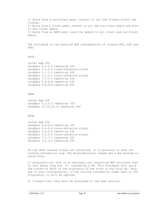
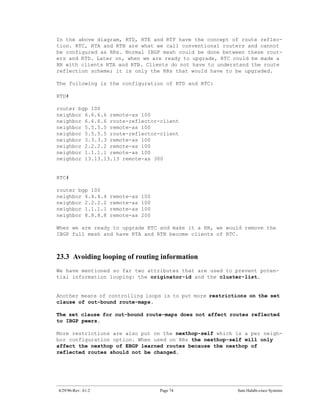
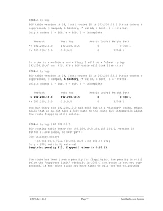
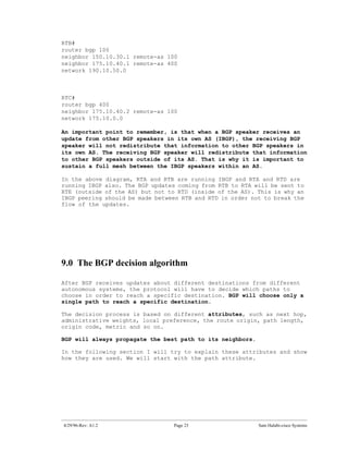
![RTB#sh ip bgp
BGP table version is 32, local router ID is 203.250.15.2 Status codes:
s suppressed, d damped, h history, * valid, > best, i - internal Origin
codes: i - IGP, e - EGP, ? - incomplete
Network Next Hop Metric LocPrf Weight Path
*d 192.208.10.0 192.208.10.5 0 0 300 i
*> 203.250.15.0 0.0.0.0 0 32768 i
RTB#sh ip bgp 192.208.10.0
BGP routing table entry for 192.208.10.0 255.255.255.0, version 32
Paths: (1 available, no best path)
300, (suppressed due to dampening)
192.208.10.5 from 192.208.10.5 (192.208.10.174)
Origin IGP, metric 0, valid, external
Dampinfo: penalty 2615, flapped 3 times in 0:05:18 , reuse in 0:27:00
The route has been dampened (suppressed). The route will be reused when
the penalty reaches the “reuse value”, in our case 750 (default).The
dampening information will be purged when the penalty becomes less than
half of the reuse-limit, in our case (750/2=375). The Following are the
commands used to show and clear flap statistics information:
show ip bgp flap-statistics
(displays flap statistics for all the paths)
show ip bgp-flap-statistics regexp <regexp>
(displays flap statistics for all paths that match the regexp)
show ip bgp flap-statistics filter-list <list>
(displays flap statistics for all paths that pass the filter)
show ip bgp flap-statistics A.B.C.D m.m.m.m
(displays flap statistics for a single entry)
show ip bgp flap-statistics A.B.C.D m.m.m.m longer-prefixes
(displays flap statistics for more specific entries)
show ip bgp neighbor [dampened-routes] | [flap-statistics]
(displays flap statistics for all paths from a neighbor)
clear ip bgp flap-statistics (clears flap statistics for all routes)
clear ip bgp flap-statistics regexp <regexp>
(clears flap statistics for all the paths that match the regexp)
clear ip bgp flap-statistics filter-list <list>
(clears flap statistics for all the paths that pass the filter)
clear ip bgp flap-statistics A.B.C.D m.m.m.m
(clears flap statistics for a single entry)
clear ip bgp A.B.C.D flap-statistics
(clears flap statistics for all paths from a neighbor)
4/29/96-Rev: A1.2 Page 78 Sam Halabi-cisco Systems](https://image.slidesharecdn.com/halabibgp4casestudiestutorial-13461527622183-phpapp01-120828062052-phpapp01/85/Halabi-Bgp4-Case-Studies-Tutorial-78-320.jpg)
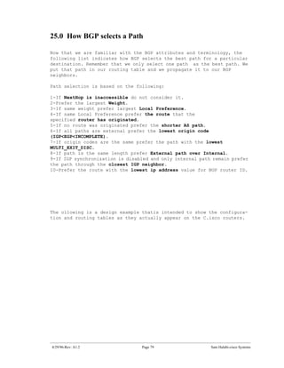
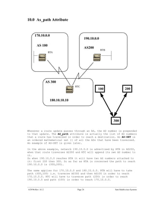
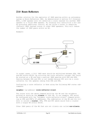
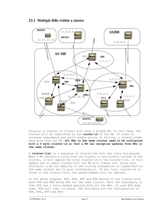
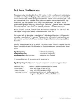
![The > symbol indicates that BGP has chosen the best route based on the
list of decision steps that I have gone through earlier in this document
under "How BGP selects a Path". Bgp will only pick one best Path to
reach a destination, will install this path in the ip routing table
and will advertise it to other bgp peers. Notice the nexthop
attribute. RTB knows about 128.213.0.0 via a nexthop of 128.213.63.2
which is the ebgp nexthop carried into IBGP.
Let us look at the IP routing table:
RTB#sh ip rou
Codes: C - connected, S - static, I - IGRP, R - RIP, M - mobile, B - BGP
D - EIGRP, EX - EIGRP external, O - OSPF, IA - OSPF inter area
E1 - OSPF external type 1, E2 - OSPF external type 2, E - EGP
i - IS-IS, L1 - IS-IS level-1, L2 - IS-IS level-2, * - candidate
default
Gateway of last resort is not set
203.250.13.0 255.255.255.255 is subnetted, 1 subnets
O 203.250.13.41 [110/75] via 203.250.15.1, 02:50:45, Serial0
203.250.15.0 255.255.255.252 is subnetted, 1 subnets
C 203.250.15.0 is directly connected, Serial0
O 203.250.14.0 [110/74] via 203.250.15.1, 02:50:46, Serial0
Well, it doesn't look like any of the BGP entries has made it to the
routing table. There are two problems here:
Problem 1:
The Nexthop for these entries 128.213.63.2 is unreachable. This is
true because we do not have a way to reach that nexthop via our
IGP (OSPF). RTB has not learned about 128.213.63.0 via OSPF. We can
run OSPF on RTA s0 and make it passive, and this way RTB would know
how to reach the nexthop 128.213.63.2. We could also change the
nexthop by using the bgp nexthopself command between RTA and RTB.
RTA's configs would be:
4/29/96-Rev: A1.2 Page 85 Sam Halabi-cisco Systems](https://image.slidesharecdn.com/halabibgp4casestudiestutorial-13461527622183-phpapp01-120828062052-phpapp01/85/Halabi-Bgp4-Case-Studies-Tutorial-85-320.jpg)
![RTB#sh ip rou
Codes: C - connected, S - static, I - IGRP, R - RIP, M - mobile, B - BGP
D - EIGRP, EX - EIGRP external, O - OSPF, IA - OSPF inter area
E1 - OSPF external type 1, E2 - OSPF external type 2, E - EGP
i - IS-IS, L1 - IS-IS level-1, L2 - IS-IS level-2, * -
candidate default
Gateway of last resort is not set
203.250.13.0 255.255.255.255 is subnetted, 1 subnets
O 203.250.13.41 [110/75] via 203.250.15.1, 00:04:46, Serial0
203.250.15.0 255.255.255.252 is subnetted, 1 subnets
C 203.250.15.0 is directly connected, Serial0
O 203.250.14.0 [110/74] via 203.250.15.1, 00:04:46, Serial0
128.213.0.0 255.255.255.252 is subnetted, 1 subnets
O 128.213.63.0 [110/138] via 203.250.15.1, 00:04:47, Serial0
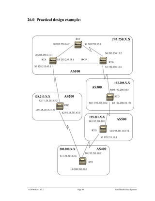
Problem 2:
We still do not see the BGP entries; the only difference is that
128.213.63.0 is now reachable via OSPF. This is the synchronization
issue, BGP is not putting these entries in the routing table and will
not send them in BGP updates because it is not synchronized with the
IGP. Note that RTF has no notion of networks 192.208.10.0 or
195.211.10.0 because we have not redistributed BGP into OSPF yet.
In this scenario, if we turn synchronization off, we will have the
entries in the routing table, but connectivity would still be broken.
If you turn off synchronization on RTB this is what will happen:
4/29/96-Rev: A1.2 Page 87 Sam Halabi-cisco Systems](https://image.slidesharecdn.com/halabibgp4casestudiestutorial-13461527622183-phpapp01-120828062052-phpapp01/85/Halabi-Bgp4-Case-Studies-Tutorial-87-320.jpg)
![RTB#sh ip rou
Codes: C - connected, S - static, I - IGRP, R - RIP, M - mobile, B - BGP
D - EIGRP, EX - EIGRP external, O - OSPF, IA - OSPF inter area
E1 - OSPF external type 1, E2 - OSPF external type 2, E - EGP
i - IS-IS, L1 - IS-IS level-1, L2 - IS-IS level-2, * -
candidate default
Gateway of last resort is not set
B 200.200.10.0 [200/0] via 128.213.63.2, 00:01:07
B 195.211.10.0 [200/0] via 128.213.63.2, 00:01:07
B 192.208.10.0 [200/0] via 128.213.63.2, 00:01:07
203.250.13.0 is variably subnetted, 2 subnets, 2 masks
O 203.250.13.41 255.255.255.255
[110/75] via 203.250.15.1, 00:12:37, Serial0
B 203.250.13.0 255.255.255.0 [200/0] via 203.250.13.41, 00:01:08
203.250.15.0 255.255.255.252 is subnetted, 1 subnets
C 203.250.15.0 is directly connected, Serial0
O 203.250.14.0 [110/74] via 203.250.15.1, 00:12:37, Serial0
128.213.0.0 is variably subnetted, 2 subnets, 2 masks
B 128.213.0.0 255.255.0.0 [200/0] via 128.213.63.2, 00:01:08
O 128.213.63.0 255.255.255.252
[110/138] via 203.250.15.1, 00:12:37, Serial0
The routing table looks fine, but there is no way we can reach those
networks because RTF in the middle does not know how to reach them:
RTF#sh ip rou
Codes: C - connected, S - static, I - IGRP, R - RIP, M - mobile, B - BGP
D - EIGRP, EX - EIGRP external, O - OSPF, IA - OSPF inter area
E1 - OSPF external type 1, E2 - OSPF external type 2, E - EGP
i - IS-IS, L1 - IS-IS level-1, L2 - IS-IS level-2, * -
candidate default
Gateway of last resort is not set
203.250.13.0 255.255.255.255 is subnetted, 1 subnets
O 203.250.13.41 [110/11] via 203.250.14.1, 00:14:15, Ethernet0
203.250.15.0 255.255.255.252 is subnetted, 1 subnets
C 203.250.15.0 is directly connected, Serial1
C 203.250.14.0 is directly connected, Ethernet0
128.213.0.0 255.255.255.252 is subnetted, 1 subnets
O 128.213.63.0 [110/74] via 203.250.14.1, 00:14:15, Ethernet0
So, turning off synchronization in this situation did not help this
particular issue, but we will need it for other issues later on.
Let’s redistribute OSPF into BGP on RTA , with a metric of
2000.
4/29/96-Rev: A1.2 Page 88 Sam Halabi-cisco Systems](https://image.slidesharecdn.com/halabibgp4casestudiestutorial-13461527622183-phpapp01-120828062052-phpapp01/85/Halabi-Bgp4-Case-Studies-Tutorial-88-320.jpg)
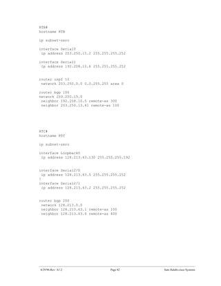
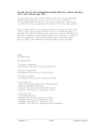
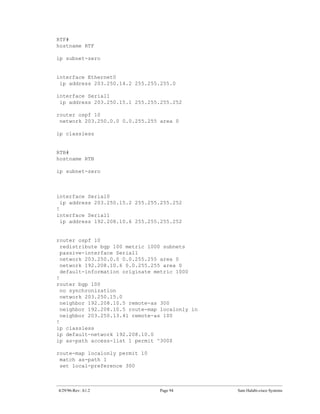
![RTA#
hostname RTA
ip subnet-zero
interface Loopback0
ip address 203.250.13.41 255.255.255.0
interface Ethernet0
ip address 203.250.14.1 255.255.255.0
interface Serial0
ip address 128.213.63.1 255.255.255.252
router ospf 10
redistribute bgp 100 metric 2000 subnets
passive-interface Serial0
network 203.250.0.0 0.0.255.255 area 0
network 128.213.0.0 0.0.255.255 area 0
router bgp 100
network 203.250.0.0 mask 255.255.0.0
neighbor 128.213.63.2 remote-as 200
neighbor 203.250.15.2 remote-as 100
neighbor 203.250.15.2 update-source Loopback0
The routing table will look like this:
RTB#sh ip rou
Codes: C - connected, S - static, I - IGRP, R - RIP, M - mobile, B - BGP
D - EIGRP, EX - EIGRP external, O - OSPF, IA - OSPF inter area
E1 - OSPF external type 1, E2 - OSPF external type 2, E - EGP
i - IS-IS, L1 - IS-IS level-1, L2 - IS-IS level-2, * -
candidate default
Gateway of last resort is not set
O E2 200.200.10.0 [110/2000] via 203.250.15.1, 00:00:14, Serial0
O E2 195.211.10.0 [110/2000] via 203.250.15.1, 00:00:14, Serial0
O E2 192.208.10.0 [110/2000] via 203.250.15.1, 00:00:14, Serial0
203.250.13.0 is variably subnetted, 2 subnets, 2 masks
O 203.250.13.41 255.255.255.255
[110/75] via 203.250.15.1, 00:00:15, Serial0
O E2 203.250.13.0 255.255.255.0
[110/2000] via 203.250.15.1, 00:00:15, Serial0
203.250.15.0 255.255.255.252 is subnetted, 2 subnets
C 203.250.15.8 is directly connected, Loopback1
C 203.250.15.0 is directly connected, Serial0
O 203.250.14.0 [110/74] via 203.250.15.1, 00:00:15, Serial0
128.213.0.0 is variably subnetted, 2 subnets, 2 masks
O E2 128.213.0.0 255.255.0.0 [110/2000] via 203.250.15.1,
00:00:15,Serial0
O 128.213.63.0 255.255.255.252
[110/138] via 203.250.15.1, 00:00:16, Serial0
4/29/96-Rev: A1.2 Page 89 Sam Halabi-cisco Systems](https://image.slidesharecdn.com/halabibgp4casestudiestutorial-13461527622183-phpapp01-120828062052-phpapp01/85/Halabi-Bgp4-Case-Studies-Tutorial-89-320.jpg)
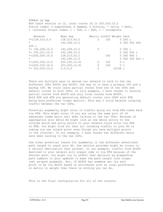
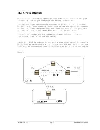
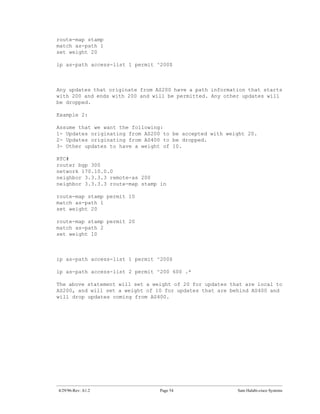
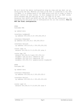
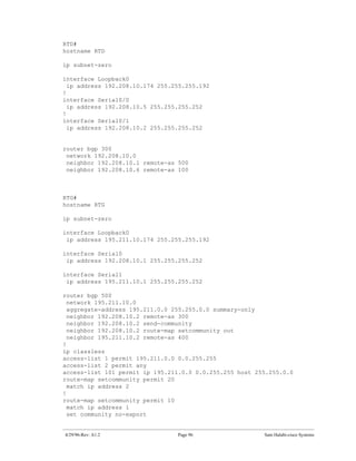
![For RTB, the local preference for updates coming in from AS300 is set
to 300 which is higher than the IBGP updates coming in from RTA. This
way AS100 will pick RTB for AS300’s local routes. Any other routes on
RTB (if they exist) will be sent internally with a local preference of
100 which is lower than 200 coming in from RTA, and this way RTA will be
preferred.
Note that I have only advertised AS300’s local routes. Any path info
that does not match ^300$ will be dropped. If you wanted to advertise
the local routes and the neighbor routes (customers of the ISP) you
can use the following: ^300_[0-9]*
This is the output of the regular expression indicating AS300’s local
routes:
RTB#sh ip bgp regexp ^300$
BGP table version is 14, local router ID is 203.250.15.2
Status codes: s suppressed, d damped, h history, * valid, > best, i -
internal
Origin codes: i - IGP, e - EGP, ? - incomplete
Network Next Hop Metric LocPrf Weight Path
*> 192.208.10.0 192.208.10.5 0 300 0 300
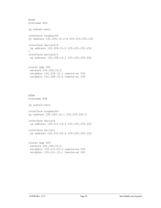
RTC#
hostname RTC
ip subnet-zero
interface Loopback0
ip address 128.213.63.130 255.255.255.192
interface Serial2/0
ip address 128.213.63.5 255.255.255.252
!
interface Serial2/1
ip address 128.213.63.2 255.255.255.252
router bgp 200
network 128.213.0.0
aggregate-address 128.213.0.0 255.255.0.0 summary-only
neighbor 128.213.63.1 remote-as 100
neighbor 128.213.63.1 distribute-list 1 out
neighbor 128.213.63.6 remote-as 400
ip classless
access-list 1 deny 195.211.0.0 0.0.255.255
access-list 1 permit any
On RTC, I have aggregated 128.213.0.0/16 and indicated the specific
routes to be injected into AS100. If the ISP refuses to do this task
then you have to filter on the incoming end of AS100.
4/29/96-Rev: A1.2 Page 95 Sam Halabi-cisco Systems](https://image.slidesharecdn.com/halabibgp4casestudiestutorial-13461527622183-phpapp01-120828062052-phpapp01/85/Halabi-Bgp4-Case-Studies-Tutorial-95-320.jpg)
![RTA#sh ip rou
Codes: C - connected, S - static, I - IGRP, R - RIP, M - mobile, B - BGP
D - EIGRP, EX - EIGRP external, O - OSPF, IA - OSPF inter area
E1 - OSPF external type 1, E2 - OSPF external type 2, E - EGP
i - IS-IS, L1 - IS-IS level-1, L2 - IS-IS level-2, * -
candidate default
Gateway of last resort is 128.213.63.2 to network 200.200.0.0
192.208.10.0 is variably subnetted, 2 subnets, 2 masks
O E2 192.208.10.0 255.255.255.0
[110/1000] via 203.250.14.2, 00:41:25, Ethernet0
O 192.208.10.4 255.255.255.252
[110/138] via 203.250.14.2, 00:41:25, Ethernet0
C 203.250.13.0 is directly connected, Loopback0
203.250.15.0 is variably subnetted, 3 subnets, 3 masks
O 203.250.15.10 255.255.255.255
[110/75] via 203.250.14.2, 00:41:25, Ethernet0
O 203.250.15.0 255.255.255.252
[110/74] via 203.250.14.2, 00:41:25, Ethernet0
B 203.250.15.0 255.255.255.0 [200/0] via 203.250.15.2, 00:41:25
C 203.250.14.0 is directly connected, Ethernet0
128.213.0.0 is variably subnetted, 2 subnets, 2 masks
B 128.213.0.0 255.255.0.0 [20/0] via 128.213.63.2, 00:41:26
C 128.213.63.0 255.255.255.252 is directly connected, Serial0
B* 200.200.0.0 255.255.0.0 [20/0] via 128.213.63.2, 00:02:38
4/29/96-Rev: A1.2 Page 98 Sam Halabi-cisco Systems](https://image.slidesharecdn.com/halabibgp4casestudiestutorial-13461527622183-phpapp01-120828062052-phpapp01/85/Halabi-Bgp4-Case-Studies-Tutorial-98-320.jpg)
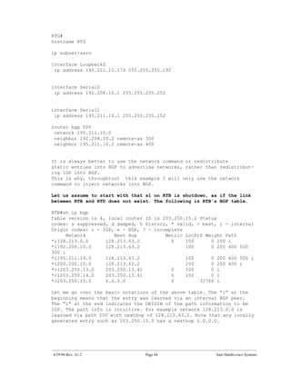
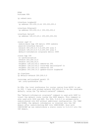
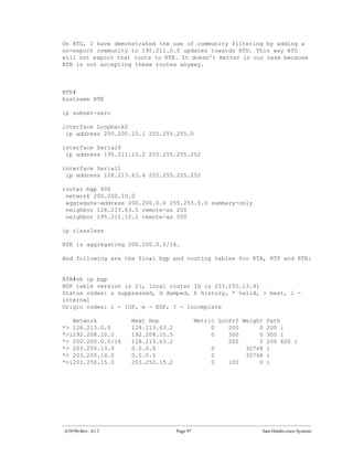
![RTF#sh ip rou
Codes: C - connected, S - static, I - IGRP, R - RIP, M - mobile, B - BGP
D - EIGRP, EX - EIGRP external, O - OSPF, IA - OSPF inter area
E1 - OSPF external type 1, E2 - OSPF external type 2, E - EGP
i - IS-IS, L1 - IS-IS level-1, L2 - IS-IS level-2, * -
candidate default
Gateway of last resort is 203.250.15.2 to network 0.0.0.0
192.208.10.0 is variably subnetted, 2 subnets, 2 masks
O E2 192.208.10.0 255.255.255.0
[110/1000] via 203.250.15.2, 00:48:50, Serial1
O 192.208.10.4 255.255.255.252
[110/128] via 203.250.15.2, 01:12:09, Serial1
203.250.13.0 is variably subnetted, 2 subnets, 2 masks
O 203.250.13.41 255.255.255.255
[110/11] via 203.250.14.1, 01:12:09, Ethernet0
O E2 203.250.13.0 255.255.255.0
[110/2000] via 203.250.14.1, 01:12:09, Ethernet0
203.250.15.0 is variably subnetted, 2 subnets, 2 masks
O 203.250.15.10 255.255.255.255
[110/65] via 203.250.15.2, 01:12:09, Serial1
C 203.250.15.0 255.255.255.252 is directly connected, Serial1
C 203.250.14.0 is directly connected, Ethernet0
128.213.0.0 is variably subnetted, 2 subnets, 2 masks
O E2 128.213.0.0 255.255.0.0
[110/2000] via 203.250.14.1, 00:45:01, Ethernet0
O 128.213.63.0 255.255.255.252
[110/74] via 203.250.14.1, 01:12:11, Ethernet0
O E2 200.200.0.0 255.255.0.0 [110/2000] via 203.250.14.1, 00:03:47,
Ethernet0
O*E2 0.0.0.0 0.0.0.0 [110/1000] via 203.250.15.2, 00:03:33, Serial1
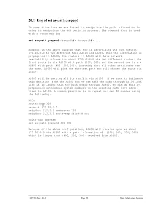
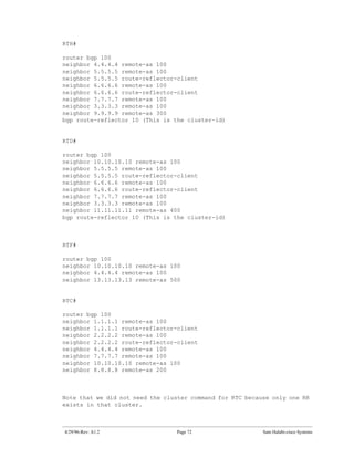
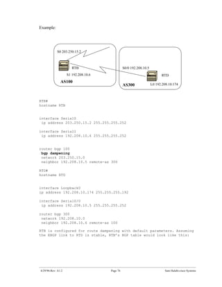
Note RTF’s routing table which indicates that networks local to
AS300 such as 192.208.10.0 are to be reached via RTB. Other known
networks such as 200.200.0.0 are to be reached via RTA. The
gateway of last resort is set to RTB. In case something
happens to the connection between RTB and RTD, then the default
advertised by RTA will kick in with a metric of 2000.
4/29/96-Rev: A1.2 Page 99 Sam Halabi-cisco Systems](https://image.slidesharecdn.com/halabibgp4casestudiestutorial-13461527622183-phpapp01-120828062052-phpapp01/85/Halabi-Bgp4-Case-Studies-Tutorial-99-320.jpg)
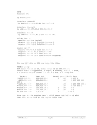
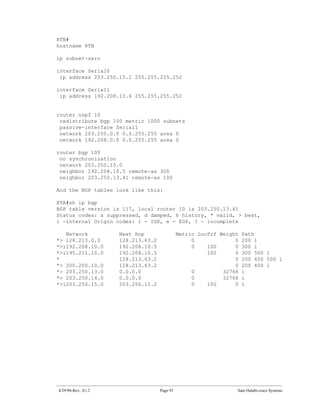
![RTB#sh ip bgp
BGP table version is 14, local router ID is 203.250.15.10
Status codes: s suppressed, d damped, h history, * valid, > best, i -
internal
Origin codes: i - IGP, e - EGP, ? - incomplete
Network Next Hop Metric LocPrf Weight Path
*>i128.213.0.0 128.213.63.2 0 200 0 200 i
*> 192.208.10.0 192.208.10.5 0 300 0 300 i
*>i200.200.0.0/16 128.213.63.2 200 0 200 400 i
*>i203.250.13.0 203.250.13.41 0 100 0 i
*>i203.250.14.0 203.250.13.41 0 100 0 i
*> 203.250.15.0 0.0.0.0 0 32768 i
RTB#sh ip rou
Codes: C - connected, S - static, I - IGRP, R - RIP, M - mobile, B - BGP
D - EIGRP, EX - EIGRP external, O - OSPF, IA - OSPF inter area
E1 - OSPF external type 1, E2 - OSPF external type 2, E - EGP
i - IS-IS, L1 - IS-IS level-1, L2 - IS-IS level-2, * -
candidate default
Gateway of last resort is 192.208.10.5 to network 192.208.10.0
* 192.208.10.0 is variably subnetted, 2 subnets, 2 masks
B* 192.208.10.0 255.255.255.0 [20/0] via 192.208.10.5, 00:50:46
C 192.208.10.4 255.255.255.252 is directly connected, Serial1
203.250.13.0 is variably subnetted, 2 subnets, 2 masks
O 203.250.13.41 255.255.255.255
[110/75] via 203.250.15.1, 01:20:33, Serial0
O E2 203.250.13.0 255.255.255.0
[110/2000] via 203.250.15.1, 01:15:40, Serial0
203.250.15.0 255.255.255.252 is subnetted, 2 subnets
C 203.250.15.8 is directly connected, Loopback1
C 203.250.15.0 is directly connected, Serial0
O 203.250.14.0 [110/74] via 203.250.15.1, 01:20:33, Serial0
128.213.0.0 is variably subnetted, 2 subnets, 2 masks
O E2 128.213.0.0 255.255.0.0 [110/2000] via 203.250.15.1, 00:46:55,
Serial0
O 128.213.63.0 255.255.255.252
[110/138] via 203.250.15.1, 01:20:34, Serial0
O E2 200.200.0.0 255.255.0.0 [110/2000] via 203.250.15.1, 00:05:42,
Serial0
4/29/96-Rev: A1.2 Page 100 Sam Halabi-cisco Systems](https://image.slidesharecdn.com/halabibgp4casestudiestutorial-13461527622183-phpapp01-120828062052-phpapp01/85/Halabi-Bgp4-Case-Studies-Tutorial-100-320.jpg)

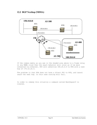
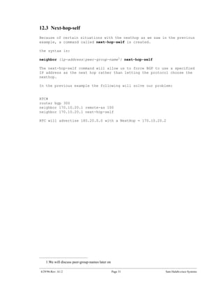
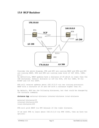
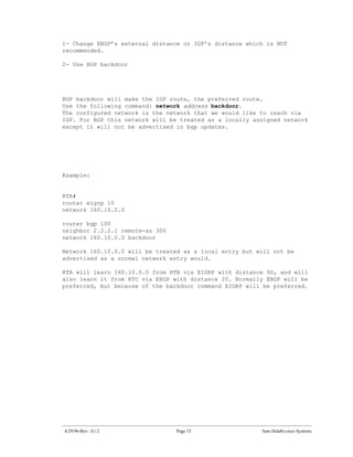
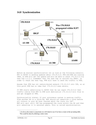
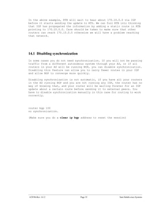
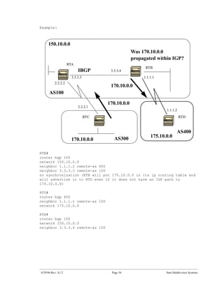
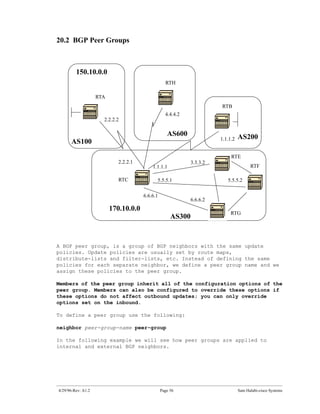
The document introduces Border Gateway Protocol (BGP) terminology and configuration, describing how to enable and configure BGP routing between internal and external peers, use loopback interfaces and multihop EBGP to establish neighbor relationships, and apply route filtering and route maps to manipulate routing behavior. It provides examples of basic BGP configuration and design concepts for both internal and external BGP.


