Download to read offline
![International Journal of Research in Engineering and Science (IJRES)
ISSN (Online): 2320-9364, ISSN (Print): 2320-9356
www.ijres.org Volume 2 Issue 2 ǁ Feb. 2014ǁ PP.48-55
www.ijres.org 48 | Page
Numerical Experiments of Hydrogen-Air Premixed Flames
M.A. Abdel-Raheem1
, S.S. Ibrahim2
, W. Malalasekera1
1
Wolfson School of Mechanical and Manufacturing Engineering, Loughborough University, UK
2
Department ofAeronautical and Automotive Engineering, Loughborough University, UK
ABSTRACT : Numerical experiments have been carried out to study turbulent premixed flames of hydrogen-
air mixtures in a small scale combustion chamber. Flow is calculated using the Large Eddy Simulation (LES)
Technique for turbulent flow. The chemical reaction is modeled using a dynamic procedure for the calculation
of the flame/flow interactions. Sensitivity of the results obtained to the computational grid, ignition source and
different flow configurations have been carried out. Numerical results are validated against published
experimental data. It was found that the grid resolution has very small effect on the results after a certain grid.
Also, the ignition source has influenced only the time where the peak overpressure appears. Finally, the different
configurations are reported to affect both the peak overpressure and flame position.
Keywords–Dynamic Flame Surface Density, Hydrogen, LES, Explosion, Reaction Rate
I. INTRODUCTION
The deployment of hydrogen as a clean fuel and energy carrier brings into consideration the safety
problems related to its use. The current interest in hydrogen is due its availability from many resources and the
fact that has no carbon emissions. However, to enable its widespread usage in practical applications, tough
challenges must be overcome regarding hydrogen and further studies are needed to develop an improved
understanding of the issues affecting the generation, storage, distribution as well as combustion of hydrogen.
The objective of the present work is to contribute to hydrogen safety by developing numerical capabilities to
compute the overpressures resulting from itsexplosion. The study uses the large eddy simulation (LES)
technique to calculate the structure of lean hydrogen flames propagating inside a vented combustion chamber
while interacting with solid obstructions. The results are validated against experimental measurements reported
by Masri et al.[1] and Al-Harbi et al. [2].
The LEStechnique is now accepted as a reliable computational tool to study turbulent flames both
premixed and non-premixed [3-8] despite its added computational cost. A key advantage of LES lies in its
ability to compute the complex dynamics of turbulent flows and resolve transient processes such as flame
propagation, instability, extinction, as well as ignition. The cost and accuracy of LES solutions lie between
direct numerical simulation (DNS) and Reynolds Averaged Navier-Stokes (RANS) techniques. A crucial
challenge to the advancement of LES lies in the development of adequate sub-grid-scale (SGS) models, which
are capable of representing combustion over a wide range of flow and combustion conditions. This paper makes
a contribution towards this objective.
As the reaction zone thickness of the premixed flame to be resolved is thin, with a characteristic length
scale much smaller than a typical LES filter width, an appropriate SGS model is needed to account for chemical
reaction. Earlier studies [9, 10] using the dynamic flame surface density (DFSD) model based on laminar
flamelets were promising in predicting key characteristics of propagating turbulent premixed flames with built-
in solid obstructions. The work presented in this paper is a continuation of previous research [9, 10] where
progress has been made in the development of the DFSD model to account for the SGS chemical reaction rate.
Here, the same strategy is applied where the DFSD model is used to simulate transient turbulent premixed
flames of hydrogen-air mixtures with equivalence ratio of 0.7, propagating in a small vented chamber having
baffles and a square solid obstacle. The experimental test facility [1] offered the capability to configure various
flow configurations with a range of turbulent flow conditions. The simulations are carried out using different
grid resolution and the results are examined for a number of ignition source strength as well as different flow
conditions. The numerical results are then validated against experimental data reported in[1, 2].
II. REACTION RATE CLOSURE
The experimental chamber used in this study was developed by the University of Sydney, Australia [1,
2]. The combustion chamber has dimensions of 50 x 50 x 250 mm and consists of 3 baffle plates located at
equidistance and a solid square obstacle of size 12 x 12 mm at about 96 mm from the ignition end (Fig. 1a). In
the experiments the hydrogen-air mixture enters the atmospheric pressure chamber, where the mixture is](https://image.slidesharecdn.com/h0224855-150115005932-conversion-gate02/85/Numerical-Experiments-of-Hydrogen-Air-Premixed-Flames-1-320.jpg)
![International Journal of Research in Engineering and Science (IJRES)
ISSN (Online): 2320-9364, ISSN (Print): 2320-9356
www.ijres.org Volume 2 Issue 2 ǁ Feb. 2014ǁ PP.48-55
www.ijres.org 48 | Page
Numerical Experiments of Hydrogen-Air Premixed Flames
M.A. Abdel-Raheem1
, S.S. Ibrahim2
, W. Malalasekera1
1
Wolfson School of Mechanical and Manufacturing Engineering, Loughborough University, UK
2
Department ofAeronautical and Automotive Engineering, Loughborough University, UK
ABSTRACT : Numerical experiments have been carried out to study turbulent premixed flames of hydrogen-
air mixtures in a small scale combustion chamber. Flow is calculated using the Large Eddy Simulation (LES)
Technique for turbulent flow. The chemical reaction is modeled using a dynamic procedure for the calculation
of the flame/flow interactions. Sensitivity of the results obtained to the computational grid, ignition source and
different flow configurations have been carried out. Numerical results are validated against published
experimental data. It was found that the grid resolution has very small effect on the results after a certain grid.
Also, the ignition source has influenced only the time where the peak overpressure appears. Finally, the different
configurations are reported to affect both the peak overpressure and flame position.
Keywords–Dynamic Flame Surface Density, Hydrogen, LES, Explosion, Reaction Rate
I. INTRODUCTION
The deployment of hydrogen as a clean fuel and energy carrier brings into consideration the safety
problems related to its use. The current interest in hydrogen is due its availability from many resources and the
fact that has no carbon emissions. However, to enable its widespread usage in practical applications, tough
challenges must be overcome regarding hydrogen and further studies are needed to develop an improved
understanding of the issues affecting the generation, storage, distribution as well as combustion of hydrogen.
The objective of the present work is to contribute to hydrogen safety by developing numerical capabilities to
compute the overpressures resulting from itsexplosion. The study uses the large eddy simulation (LES)
technique to calculate the structure of lean hydrogen flames propagating inside a vented combustion chamber
while interacting with solid obstructions. The results are validated against experimental measurements reported
by Masri et al.[1] and Al-Harbi et al. [2].
The LEStechnique is now accepted as a reliable computational tool to study turbulent flames both
premixed and non-premixed [3-8] despite its added computational cost. A key advantage of LES lies in its
ability to compute the complex dynamics of turbulent flows and resolve transient processes such as flame
propagation, instability, extinction, as well as ignition. The cost and accuracy of LES solutions lie between
direct numerical simulation (DNS) and Reynolds Averaged Navier-Stokes (RANS) techniques. A crucial
challenge to the advancement of LES lies in the development of adequate sub-grid-scale (SGS) models, which
are capable of representing combustion over a wide range of flow and combustion conditions. This paper makes
a contribution towards this objective.
As the reaction zone thickness of the premixed flame to be resolved is thin, with a characteristic length
scale much smaller than a typical LES filter width, an appropriate SGS model is needed to account for chemical
reaction. Earlier studies [9, 10] using the dynamic flame surface density (DFSD) model based on laminar
flamelets were promising in predicting key characteristics of propagating turbulent premixed flames with built-
in solid obstructions. The work presented in this paper is a continuation of previous research [9, 10] where
progress has been made in the development of the DFSD model to account for the SGS chemical reaction rate.
Here, the same strategy is applied where the DFSD model is used to simulate transient turbulent premixed
flames of hydrogen-air mixtures with equivalence ratio of 0.7, propagating in a small vented chamber having
baffles and a square solid obstacle. The experimental test facility [1] offered the capability to configure various
flow configurations with a range of turbulent flow conditions. The simulations are carried out using different
grid resolution and the results are examined for a number of ignition source strength as well as different flow
conditions. The numerical results are then validated against experimental data reported in[1, 2].
II. REACTION RATE CLOSURE
The experimental chamber used in this study was developed by the University of Sydney, Australia [1,
2]. The combustion chamber has dimensions of 50 x 50 x 250 mm and consists of 3 baffle plates located at
equidistance and a solid square obstacle of size 12 x 12 mm at about 96 mm from the ignition end (Fig. 1a). In
the experiments the hydrogen-air mixture enters the atmospheric pressure chamber, where the mixture is](https://image.slidesharecdn.com/h0224855-150115005932-conversion-gate02/75/Numerical-Experiments-of-Hydrogen-Air-Premixed-Flames-1-2048.jpg)
![Numerical Experiments of Hydrogen-Air Premixed Flames
www.ijres.org 49 | Page
allowed to settle before being ignited by focusing the infrared output from a Nd:YAG laser 2 mm above the base.
A hinged flap on top of the chamber contains the mixture during fill time prior to ignition. This flap is raised
just before ignition and is maintained through the combustion process to allow venting.
(a)(b)
Fig. 1:(a) Schematic diagram for the Sydney combustion chamber with 3-baffles (dimensions in mm). (b) Illustration of the
computational domain with the combustion chamber and the obstacles are superimposed over grid resolution.
III. THE COMBUSTION MODEL
In LES, modelling the reaction rate in turbulent premixed flames is very challenging due to its non-
linear relation with chemical and thermodynamic states. It is often characterized by propagating thin reaction
sheets or layers thinner than the smallest turbulent scales. In the present simulations, the SGS chemical reaction
rate is accounted for by using a recently developed DFSD model [4, 9, 10] modified for hydrogen flames.Brief
details of the model are given here. More details can be found elsewhere [9].
The mean SGS chemical reaction rate (ωc) is the source term, which is modelled by following the laminar
flamelet approach as:
𝜔𝑐 = 𝜌 𝑢 𝑢 𝐿∑ (1)
Where (u) is the density of unburned mixture, (𝑢 𝐿) is the laminar burning velocity, and () is the flame surface
density (FSD). The filtered flame surface density in Eq. (1) can be split into two terms as resolved and
unresolved:
∑ = ∇𝑐 = 𝑐 , ∆
𝑅𝑒𝑠𝑜𝑙𝑣𝑒𝑑
+ 𝑓 𝑐 , ∆ , 𝑐 , ∆
𝑈𝑛𝑟𝑒𝑠𝑜𝑙𝑣𝑒𝑑
(2)
Where (𝑐) is the mean reaction progress variable, () is the filter width. The over-bar describes application of
the spatial filter. The unresolved term ( 𝜆) in the above equation is evaluated using the following expression:
𝜆 = ∑ − 𝑐 , ∆ = ∇𝑐 − 𝑐 , ∆ (3)
Defining () as a ratio of test filter to grid filter, taken here equals 2 and applying the test filter (^) to flame
surface density Eq. (2) leads to:
∑ = ∇𝑐 = 𝑐 , ∆
𝑅𝑒𝑠𝑜𝑙𝑣𝑒𝑑 𝑎𝑡 𝑡𝑒𝑠𝑡𝑓𝑖𝑙𝑡𝑒𝑟
+ ∇𝑐 − 𝑐 , ∆
𝑈𝑛𝑟𝑒𝑠𝑜𝑙𝑣𝑒𝑑 𝑎𝑡 𝑡𝑒𝑠𝑡𝑓𝑖𝑙𝑡𝑒𝑟
(4)
From the above equation, the unresolved flame surface density (Λ) contribution at the test filter level can be
written as:
Baffles
Ignition Source
Solid Obstacle
Out Flow
Solid Wall
250
S2
3
3
3
10
12
S1
S3
Obstacle
(small)
Inlet
Pressure
Transducer
1
Pressure
Transducer 2
50
64
20
20
50
80](https://image.slidesharecdn.com/h0224855-150115005932-conversion-gate02/85/Numerical-Experiments-of-Hydrogen-Air-Premixed-Flames-2-320.jpg)
![Numerical Experiments of Hydrogen-Air Premixed Flames
www.ijres.org 50 | Page
Λ = ∇𝑐 − 𝑐 , ∆ (5)
Assuming the sub-grid scale contribution of unresolved flame surface density at test filter is the same as that at
grid filter and relating () and () by using Germano identity [11]:
Λ − 𝜆 = ∇𝑐 − 𝑐 , ∆ − ∇𝑐 − 𝑐 , ∆ Λ − 𝜆 = 𝑐 , ∆ − 𝑐 , ∆ (6)
The sub-grid scale flame surface density contribution from the above equation can be added to the resolved
flame surface density in Eq. (4) with a model coefficient (Cs) in order to obtain total flame surface density.
Hence the flame surface density can be expressed as:
∑ = 𝑐 , ∆ + 𝐶𝑠 𝑐 , ∆ − 𝑐 , ∆ (7)
The model coefficient (Cs) in above equation is dynamically obtained by identifying subgrid-scale flame surface
as a fractal surface [4] as follows:
𝐶𝑠 =
1
1− 𝛾2−𝐷
∆
𝛿 𝑐
𝐷−2
− 1 (8)
Where (δc) is the lower cut-off scale, (γ) is the ratio of test filter to grid filter and (D) is the fractal dimension,
calculated dynamically from [4].
𝐷 = 2.0 +
log 𝑐 ,∆ 𝑐 ,∆
log ∆ ∆
(9)
The angular brackets ‘’ in the previous equation indicates conditional averaging within the flame bounded by c
= 0 to c = 1.
The other parameters used in the present work are; equivalence ratio () of 0.7, a lower heating value of 286,000
(kJ/kmol) and the laminar burning velocity equals to 1.3 (m/s).The numerical model described above, has been
implemented using a modified in-house LES code[12]. The details of the computational domain arepresentedin
Fig. 1b. Other mathematical details of the code are not described here but available in our earlier publications [9,
10].
IV. RESULTS AND DISCUSSIONS
4.1 Grid Dependence Test
The practice of ensuring that the solution is grid independent is a generic demand to any RANS calculation,
LES of turbulent flames has not yet matured to this level [6]. This is generally because of the large
computational cost and modelling issues related to the subgrid-scale (SGS). However, the concept of implicit
filtering [13]is applied in this study and wasapplied successively at [6, 14, 15], where in that concept the filter
width is related to the laminar flame thickness. In the current calculations, 4 different grids have been adopted in
order to test the grid independency. The grids are; A (0.25 million), B (0.55 million), C (2.70 millions) and D
(4.70 millions). From Fig. 2,it can be seen that as the grid is refined the solution tends to match with the
experimental data but the convergence is not yet reached. On the other hand the difference between grids C&D
is around 2% for the peak overpressure, which is very close if we take into consideration the computational time,
i.e. 12 days for grid (C) and 30 days for grid (D). Also, the difference between the 2 grids is mainly at the time
shift which is about 0.8 ms. Hence, the grid independency could be considered reached after grid (C). In fact the
grid independence and the solution convergence represent the balance between the turbulence model and
reaction rate model. The other parameters for the different grids used can be found in Table 1.](https://image.slidesharecdn.com/h0224855-150115005932-conversion-gate02/85/Numerical-Experiments-of-Hydrogen-Air-Premixed-Flames-3-320.jpg)
![Numerical Experiments of Hydrogen-Air Premixed Flames
www.ijres.org 54 | Page
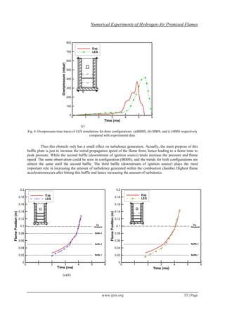
Fig. 5: Flame Position-time traces of LES simulations for three configurations. (a)BBBS, (b) BB0S, and (c) 0B0S
respectively compared with experimental data.
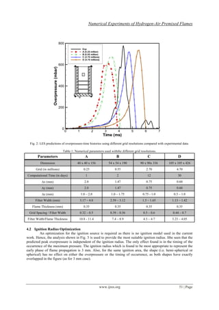
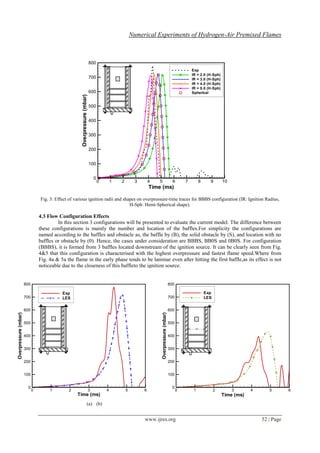
The effect of the third baffle can be only seen for the BBBS case. The square obstacle is not a
turbulence-inducing device but works to increase the blockage ratio and hence changes the development of the
flame front[2, 16]. Rapid acceleration of the flame is recorded past this obstruction followed by the wrapping of
the flame in the recirculation region, which enhances the mixing and distortion at the flame front[16].It should
be noticed here that the discrepancies (time shift and peak overpressure) between the experimental data and the
simulations could be due to many reasons. For example the ignition model, as LES combustion models based
onflame surface density assume equilibrium between turbulence and flame wrinkling which is generally not
reached as the flame is laminar at early stages[17].This could verify why the results for the 0B0S case have the
biggest difference between the experiments and the calculations as this case tends to be more laminar.
V. CONCLUSION
In the current work the dynamic flame surface density approach has been used to model the reaction
rate for hydrogen explosion inside the Sydney combustion chamber. The simulations were carried out to study
the effect of grid resolution, ignition radius and different flow configurations on the current model. Based on
that study the following observations have been concluded.
The grid independency has been reached after certain grid (grid C), although the solution convergence
is not completely achieved after this grid.
The size and shape of the ignition radius affects only at the time shift for the peak overpressure to
appear but has no effect on the value of the overpressure.
The flow configurations play an important role in the determination of the peak overpressure and
flame position, and this is because as we increase the number of baffles the levels of turbulence is
increased and hence the reaction rate. This leads to increase the values of the peak overpressure and
flame speed as the number of baffles increase.
REFERENCES
[1] Masri, A.R., AlHarbi, A., Meares, S., and Ibrahim, S.S., A Comparative Study of Turbulent Premixed Flames Propagating Past
Repeated Obstacles, Industrial and Engineering Chemistry Research, 51(22), 2011, 7690-7703.
[2] Al-Harbi, A., Masri, A.R., and Ibrahim, S.S., Turbulent Premixed Flames of CNG, LPG, and H2 Propagating Past Repeated
Obstacles, 8th
Mediterranean Combustion Symposium, Izmir, Turkey, 2013.
[3] Charlette, F., Meneveau, C., and Veynante, D., A power-law flame wrinkling model for LES of premixed turbulent combustion
Part II: dynamic formulation, Combustion and Flame, 131(1-2), 2002, 181-197.
[4] Knikker, R., Veynante, D., and Meneveau, C., A dynamic flame surface density model for large eddy simulation of turbulent
premixed combustion, Physics of Fluids, 16(11), 2004, L91-L94.
[5] Fureby, C., Pitsch, H., Lipatnikov, and Hawkes, E., A fractal flame-wrinkling large eddy simulation model for premixed
turbulent combustion, Proceedings of the Combustion Institute, 30(1), 2005, 593-601.
Time (ms)
FlamePosition(m)
0 1 2 3 4 5 6
0
0.02
0.04
0.06
0.08
0.1
0.12
0.14
0.16
0.18
0.2
Exp
LES
Sq.
Obstacle
Baffle 2
(c)](https://image.slidesharecdn.com/h0224855-150115005932-conversion-gate02/85/Numerical-Experiments-of-Hydrogen-Air-Premixed-Flames-7-320.jpg)
![Numerical Experiments of Hydrogen-Air Premixed Flames
www.ijres.org 55 | Page
[6] Masri, A.R., Ibrahim, S.S., and Cadwallader, B.J., Measurements and large eddy simulation of propagating premixed flames,
Experimental Thermal and Fluid Science, 30(7), 2006, 687-702.
[7] Pitsch, H., Large-eddy simulation of turbulent combustion, Annual Review of Fluid Mechanics, 38, 2006, 453-482.
[8] Ranga Dinesh, K.K.J., Jiang, X., Malalasekera, W., and Odedra, A., Large eddy simulation of fuel variability and flame
dynamics of hydrogen-enriched nonpremixed flames, Fuel Processing Technology, 107(0), 2013, 2-13.
[9] Gubba, S.R., Ibrahim, S.S., Malalasekera, W., and Masri, A.R., "LES modelling of propagating turbulent premixed flames using
a dynamic flame surface density model", 2nd ECCOMAS Thematic Conference on Computational Combustion, Delft,
Netherlands, 2007.
[10] Ibrahim, S.S., Gubba, S.R., Masri, A.R., and Malalasekera, W., Calculations of explosion deflagrating flames using a dynamic
flame surface density model, Journal of Loss Prevention in the Process Industries, Special Issue on CFD Simulations for
Explosion Phenomena, 22, 2009, 258-264.
[11] Germano, M., Piomelli, U., Moin, P., and Cabot, W.H., A dynamic subgrid-scale eddy viscosity model, Physics of Fluids A:
Fluid Dynamics, 3(7), 1991, 1760-1765.
[12] Gubba, S.R., Development of a dynamic LES model for premixed turbulent flames, PhD, Loughborough University, UK, 2009.
[13] Schumann, U., Large-eddy simulation of turbulent diffusion with chemical reactions in the convective boundary layer,
Atmospheric Environment (1967), 23(8), 1989, 1713-1727.
[14] Gubba, S.R., Ibrahim, S.S., Malalasekera, W., and Masri, A.R., Measurements and LES calculations of turbulent premixed flame
propagation past repeated obstacles, Combustion and Flame, 158(12), 2011, 2465-2481.
[15] Gubba, S.R., Ibrahim, S.S., Malalasekera, W., and Masri, A.R., An assessment of large eddy simulations of premixed flames
propagating past repeated obstacles, Combustion Theory and Modelling, 13(3), 2009, 513-540.
[16] Abdel-Raheem, M.A., Ibrahim, S.S., Malalasekera, W., and Masri, A.R., Large Eddy Simulation of Hydrogen-Air Propagating
Flames, 8th
Mediterranean Combustion Symposium, Izmir, Turkey, 2013.
[17] Richard, S., et al., Towards large eddy simulation of combustion in spark ignition engines, Proceedings of the Combustion
Institute, 31, 2007, 3059–3066.](https://image.slidesharecdn.com/h0224855-150115005932-conversion-gate02/85/Numerical-Experiments-of-Hydrogen-Air-Premixed-Flames-8-320.jpg)

This study investigates turbulent premixed hydrogen-air flames in a small combustion chamber using large eddy simulation (LES) to understand flame dynamics and the impact of various factors like grid resolution and ignition sources. Results indicate that grid resolution minimally affects outcomes beyond a specific threshold, while different configurations influence peak overpressure and flame position. The research aims to enhance hydrogen safety by improving numerical modeling of combustion dynamics and explosion predictions.