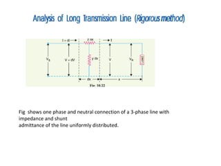
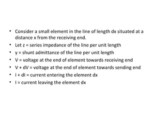
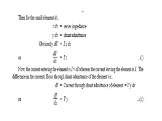
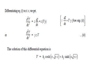
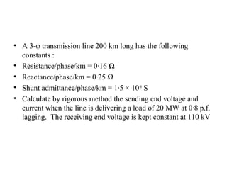
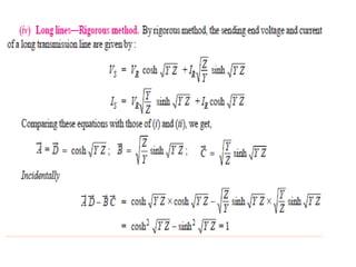
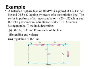
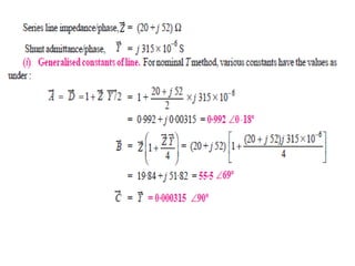
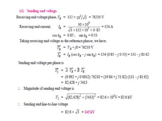
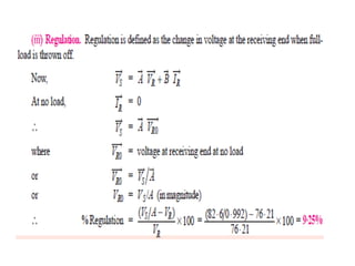
•   It is well known that line constants of the transmission line are uniformly
    distributed over the entire
•   length of the line. However, reasonable accuracy can be obtained in line
    calculations for short and
•   medium lines by considering these constants as lumped. If such an
    assumption of lumped constants
•   is applied to long transmission lines (having length excess of about 150
    km), it is found that serious
•   errors are introduced in the performance calculations. Therefore, in order
    to obtain fair degree of
•   accuracy in the performance calculations of long lines, the line constants
    are considered as uniformly
•   distributed throughout the length of the line. Rigorous mathematical
    treatment is req
•   Fig. 10.21 shows the equivalent circuit of a 3-phase long transmission line on a
    phase-neutral
•   basis. The whole line length is divided into n sections, each section having line
    constants 1/nth of those for the whole line. The following points may by noted :
•   (i) The line constants are uniformly distributed over the entire length of line as is
    actually thecase.
•   (ii) The resistance and inductive reactance are the series elements.
•   (iii) The leakage susceptance (B) and leakage conductance (G) are shunt elements.
    The leakage
•   susceptance is due to the fact that capacitance exists between line and neutral.
    The leakage
•   conductance takes into account the energy losses occurring through leakage over
    the insulators
• The leakage current through shunt admittance is maximum at
  the sending end of the line and
• decreases continuously as the receiving end of the circuit is
  approached at which point its
• value is zero.
Fig shows one phase and neutral connection of a 3-phase line with
impedance and shunt
admittance of the line uniformly distributed.
• Consider a small element in the line of length dx situated at a
  distance x from the receiving end.
• Let z = series impedance of the line per unit length
• y = shunt admittance of the line per unit length
• V = voltage at the end of element towards receiving end
• V + dV = voltage at the end of element towards sending end
• I + dI = current entering the element dx
• I = current leaving the element dx
• A 3-φ transmission line 200 km long has the following
  constants :
• Resistance/phase/km = 0·16 Ω
• Reactance/phase/km = 0·25 Ω
• Shunt admittance/phase/km = 1·5 × 10–6 S
• Calculate by rigorous method the sending end voltage and
  current when the line is delivering a load of 20 MW at 0·8 p.f.
  lagging. The receiving end voltage is kept constant at 110 kV
Example :
•   A (medium) single phase transmission line 100 km long has the following
    constants :
•   Resistance/km = 0·25 Ω ; Reactance/km = 0·8 Ω
•   Susceptance/km = 14 × 10−6 siemen ;
•   Receiving end line voltage = 66,000 V
•   Assuming that the total capacitance of the line is localised at the receiving
    end alone, determine
•   (i) the sending end current (ii) the sending end voltage (iii) regulation and
    (iv) supply power factor.
•   The line is delivering 15,000 kW at 0.8 power factor lagging. Draw the
    phasor diagram to illustrate your calculations.
Generalised Circuit Constants of a Transmission
Line
• In any four terminal *network, the input voltage and
  input current can be expressed in terms of output
  voltage and output current. Incidentally, a
  transmission line is a 4-terminal network ; two input
  terminals where power enters the network and two
  output terminals where power leaves the network.
A, B ,C and D (generally complex numbers) are the constants known as
generalised circuit constants of the transmission line.
Once the values of these constants are known, performance
calculations of the line can be easily worked out.
Example
• A balanced 3-phase load of 30 MW is supplied at 132 kV, 50
  Hz and 0·85 p.f. lagging by means of a transmission line. The
  series impedance of a single conductor is (20 + j52)ohms and
  the total phase-neutral admittance is 315 × 10−6 siemen.
  Using nominal T method, determine:
   (i) the A, B, C and D constants of the line
   (ii) sending end voltage
  (iii) regulation of the line.
Generalised circuit constants

Generalised circuit constants

  • 1.
    It is well known that line constants of the transmission line are uniformly distributed over the entire • length of the line. However, reasonable accuracy can be obtained in line calculations for short and • medium lines by considering these constants as lumped. If such an assumption of lumped constants • is applied to long transmission lines (having length excess of about 150 km), it is found that serious • errors are introduced in the performance calculations. Therefore, in order to obtain fair degree of • accuracy in the performance calculations of long lines, the line constants are considered as uniformly • distributed throughout the length of the line. Rigorous mathematical treatment is req
  • 3.
    Fig. 10.21 shows the equivalent circuit of a 3-phase long transmission line on a phase-neutral • basis. The whole line length is divided into n sections, each section having line constants 1/nth of those for the whole line. The following points may by noted : • (i) The line constants are uniformly distributed over the entire length of line as is actually thecase. • (ii) The resistance and inductive reactance are the series elements. • (iii) The leakage susceptance (B) and leakage conductance (G) are shunt elements. The leakage • susceptance is due to the fact that capacitance exists between line and neutral. The leakage • conductance takes into account the energy losses occurring through leakage over the insulators
  • 4.
    • The leakagecurrent through shunt admittance is maximum at the sending end of the line and • decreases continuously as the receiving end of the circuit is approached at which point its • value is zero.
  • 5.
    Fig shows onephase and neutral connection of a 3-phase line with impedance and shunt admittance of the line uniformly distributed.
  • 6.
    • Consider asmall element in the line of length dx situated at a distance x from the receiving end. • Let z = series impedance of the line per unit length • y = shunt admittance of the line per unit length • V = voltage at the end of element towards receiving end • V + dV = voltage at the end of element towards sending end • I + dI = current entering the element dx • I = current leaving the element dx
  • 16.
    • A 3-φtransmission line 200 km long has the following constants : • Resistance/phase/km = 0·16 Ω • Reactance/phase/km = 0·25 Ω • Shunt admittance/phase/km = 1·5 × 10–6 S • Calculate by rigorous method the sending end voltage and current when the line is delivering a load of 20 MW at 0·8 p.f. lagging. The receiving end voltage is kept constant at 110 kV
  • 17.
    Example : • A (medium) single phase transmission line 100 km long has the following constants : • Resistance/km = 0·25 Ω ; Reactance/km = 0·8 Ω • Susceptance/km = 14 × 10−6 siemen ; • Receiving end line voltage = 66,000 V • Assuming that the total capacitance of the line is localised at the receiving end alone, determine • (i) the sending end current (ii) the sending end voltage (iii) regulation and (iv) supply power factor. • The line is delivering 15,000 kW at 0.8 power factor lagging. Draw the phasor diagram to illustrate your calculations.
  • 21.
    Generalised Circuit Constantsof a Transmission Line • In any four terminal *network, the input voltage and input current can be expressed in terms of output voltage and output current. Incidentally, a transmission line is a 4-terminal network ; two input terminals where power enters the network and two output terminals where power leaves the network.
  • 22.
    A, B ,Cand D (generally complex numbers) are the constants known as generalised circuit constants of the transmission line. Once the values of these constants are known, performance calculations of the line can be easily worked out.
  • 32.
    Example • A balanced3-phase load of 30 MW is supplied at 132 kV, 50 Hz and 0·85 p.f. lagging by means of a transmission line. The series impedance of a single conductor is (20 + j52)ohms and the total phase-neutral admittance is 315 × 10−6 siemen. Using nominal T method, determine: (i) the A, B, C and D constants of the line (ii) sending end voltage (iii) regulation of the line.