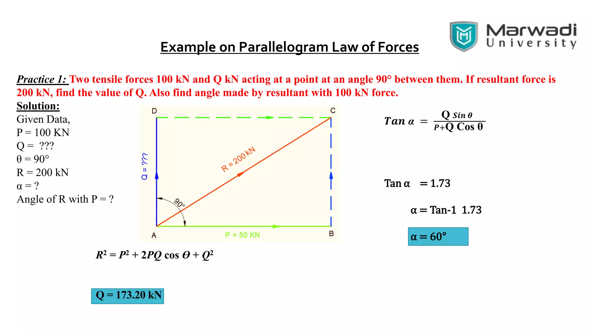
Okay, let's solve this step-by-step:
* P = 100 kN
* Angle between P and Q (θ) = 90°
* Cos 90° = 0
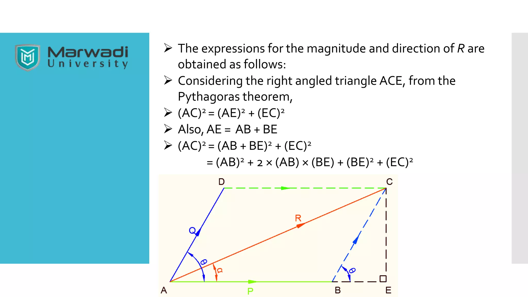
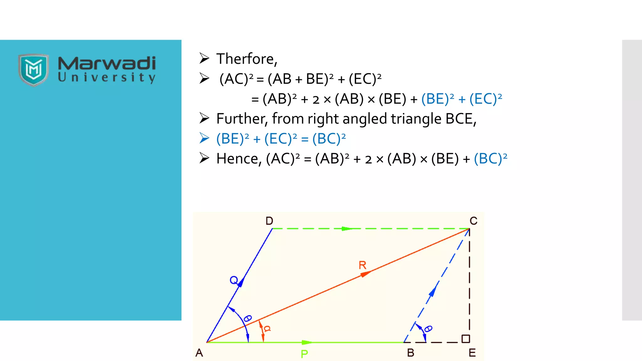
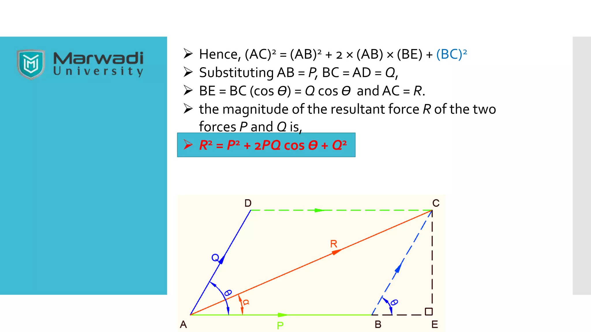
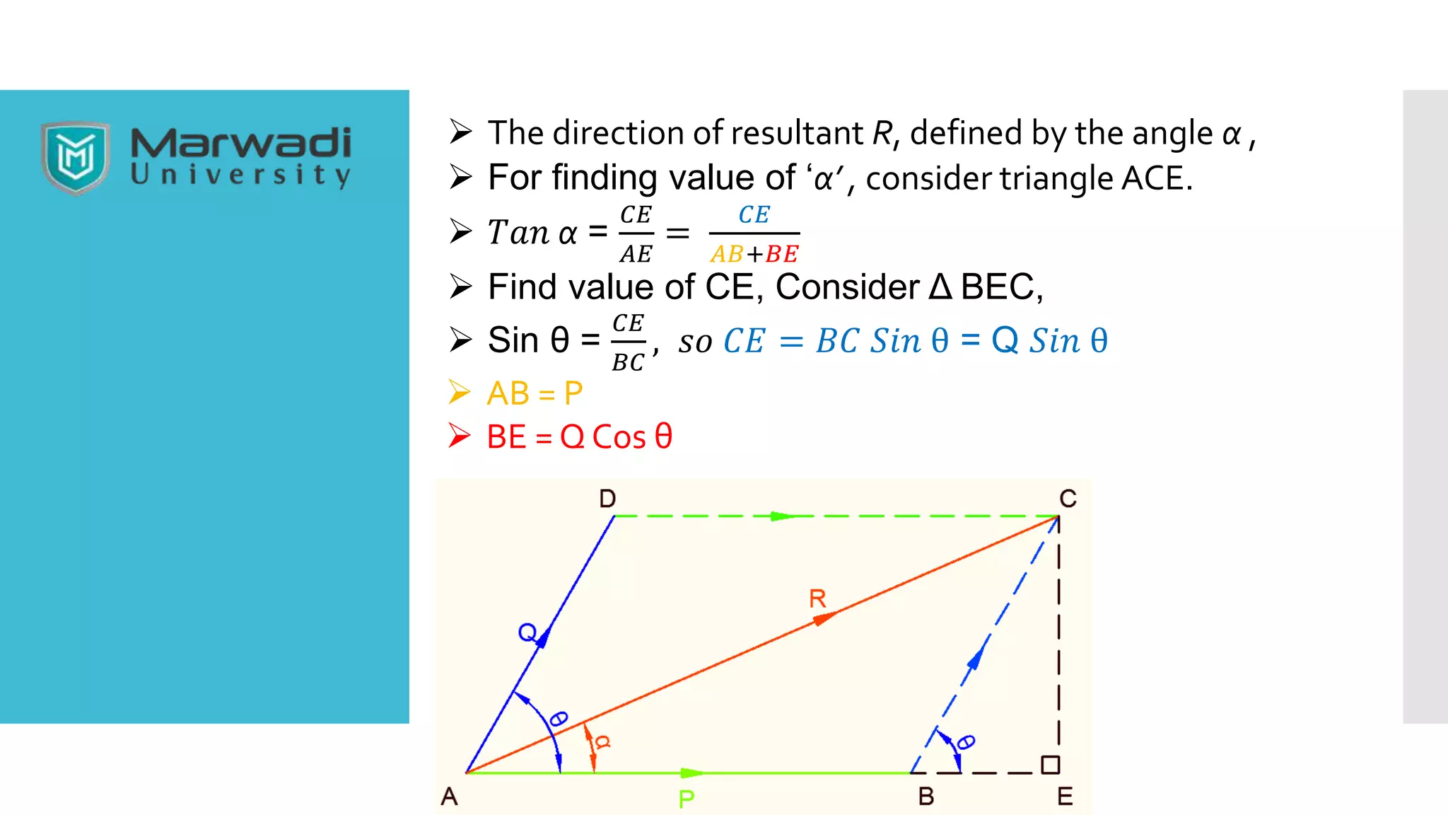
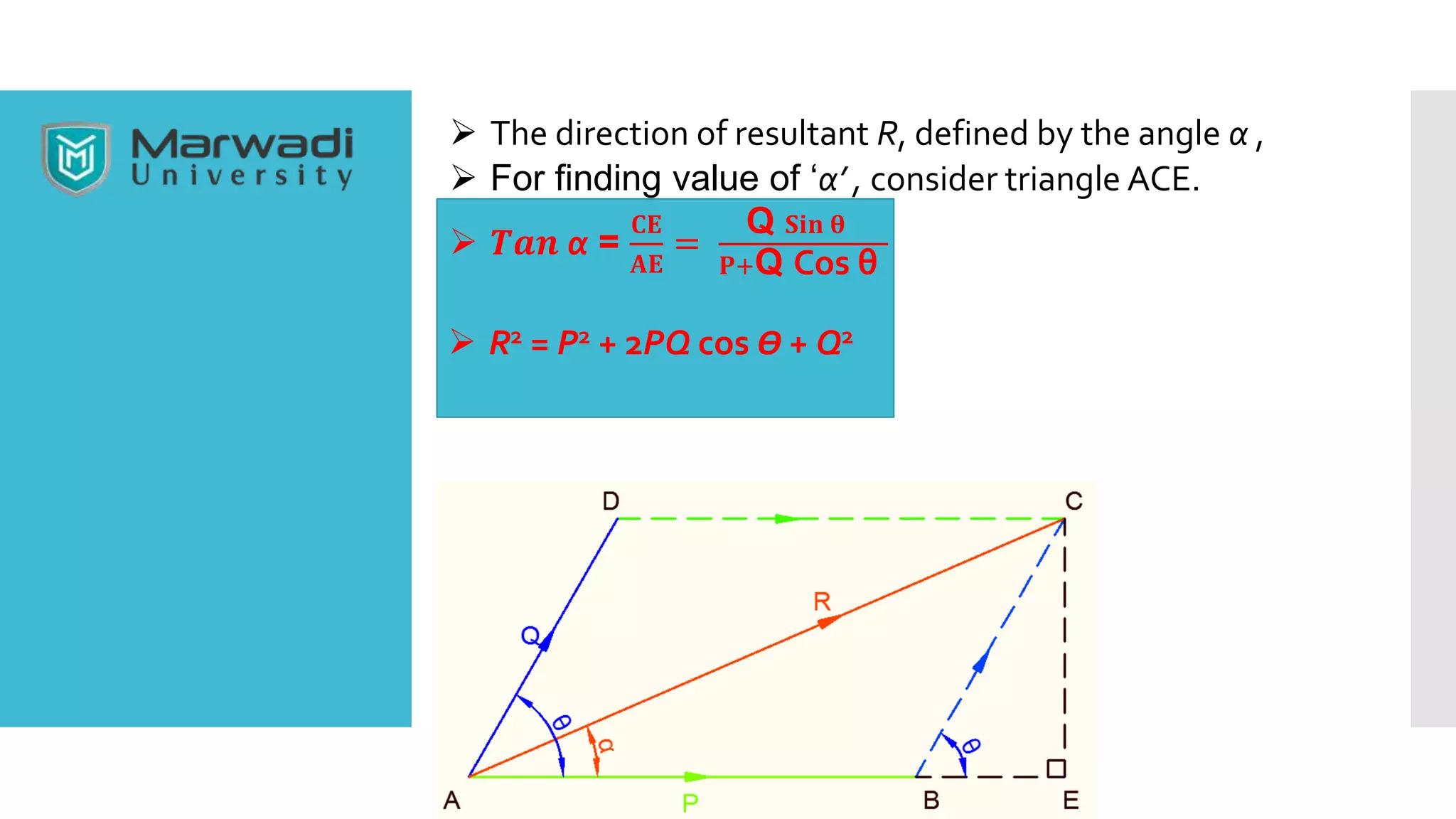
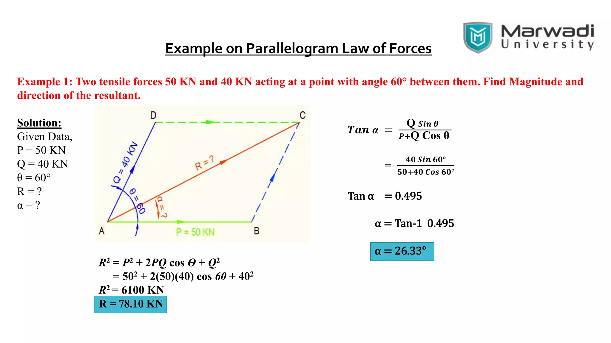
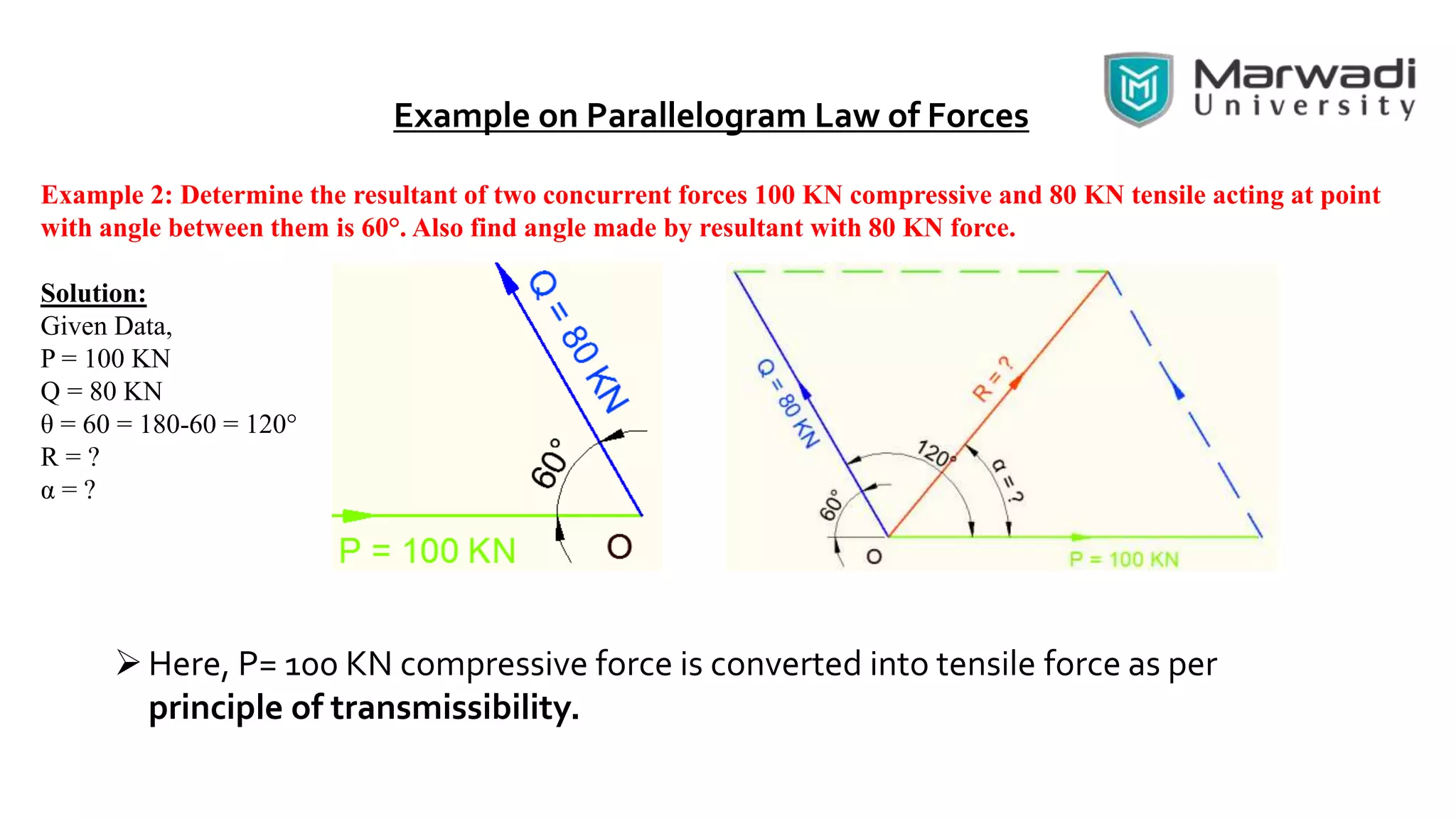
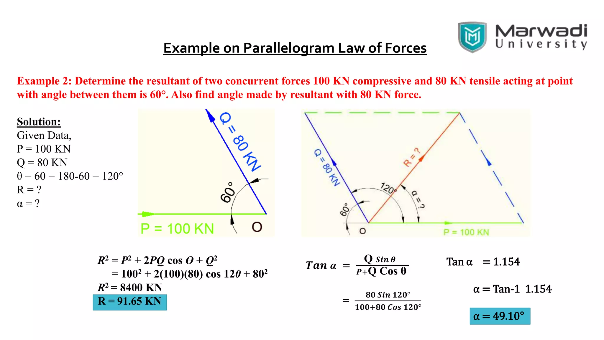
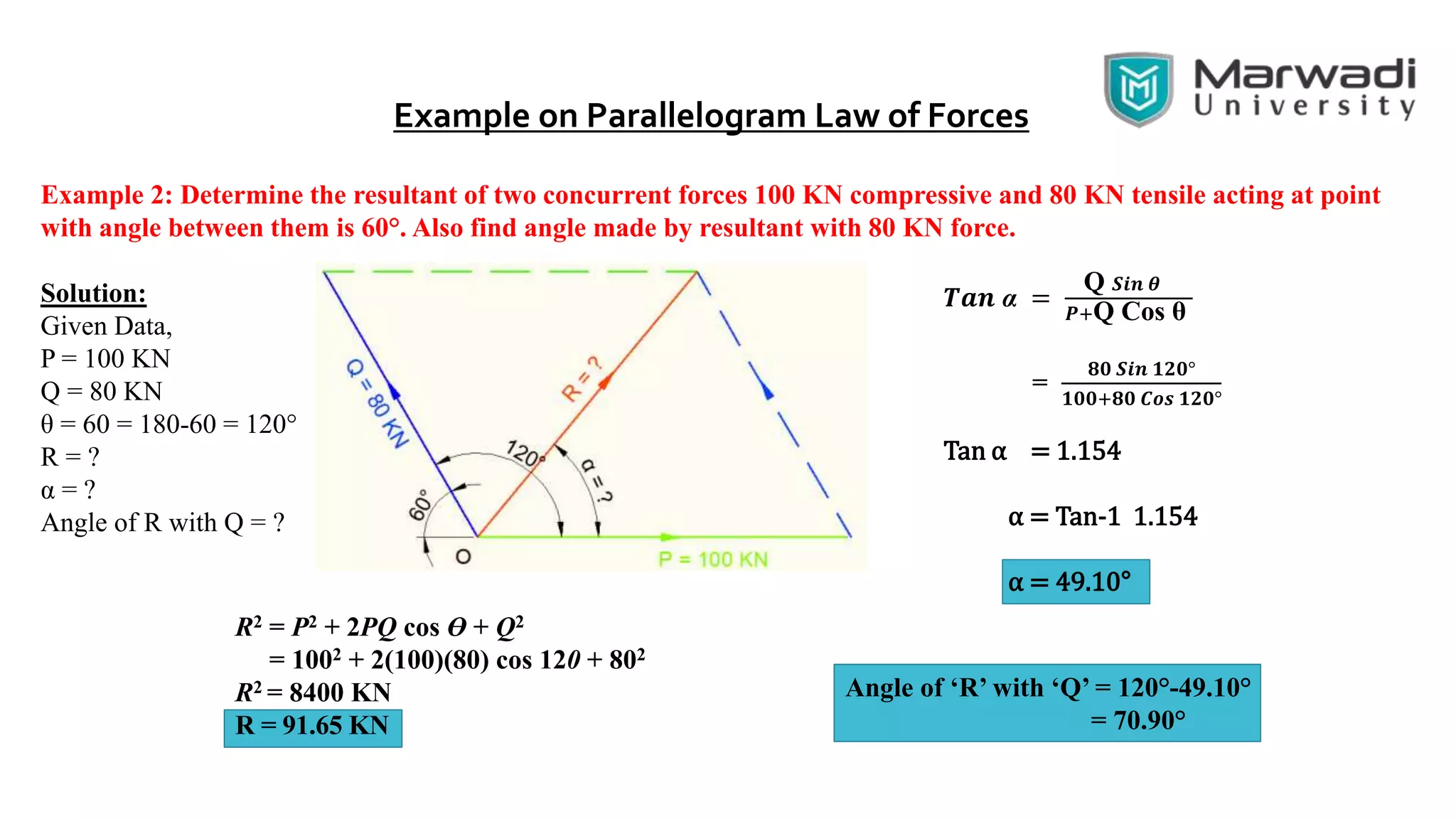
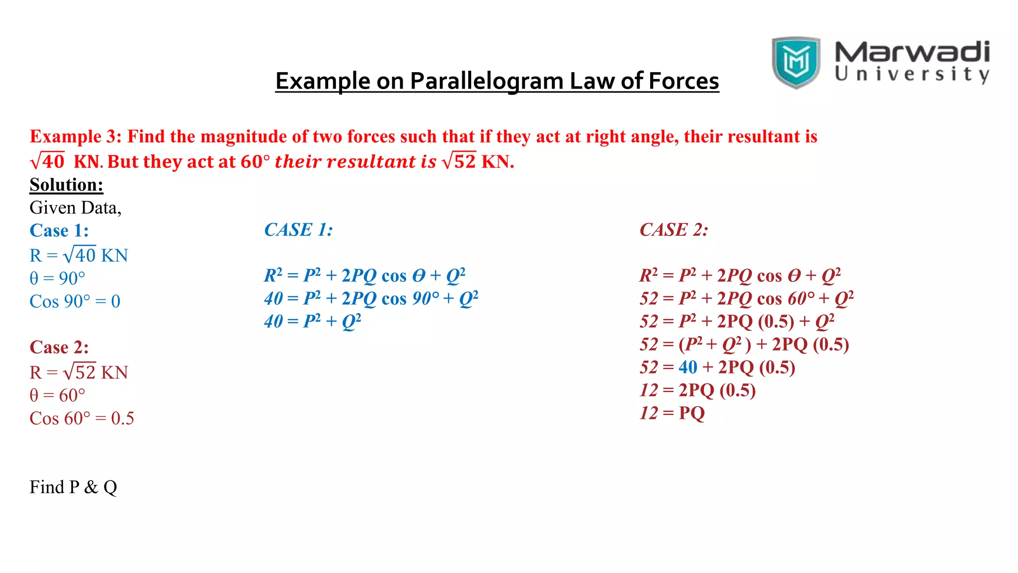
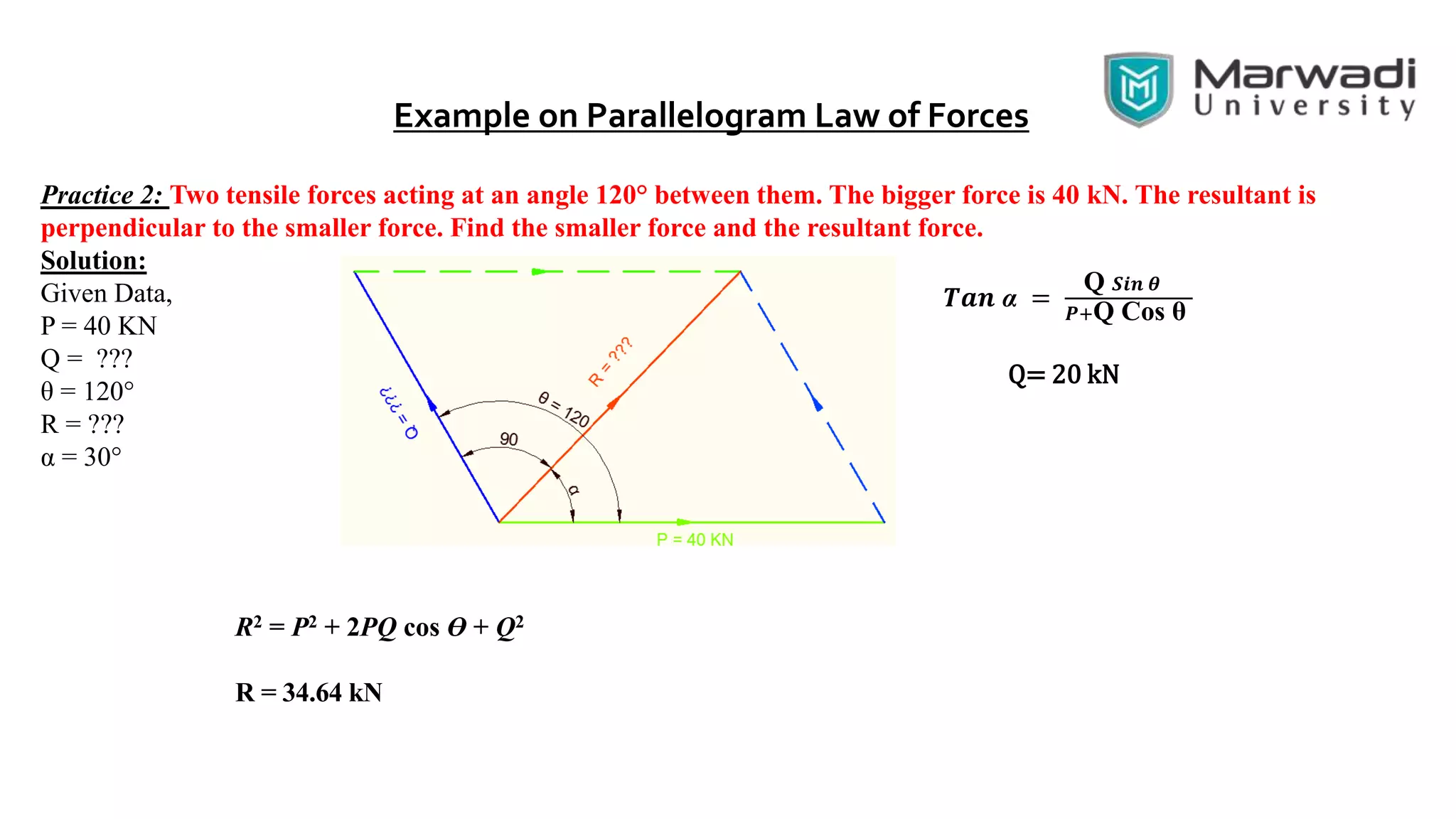
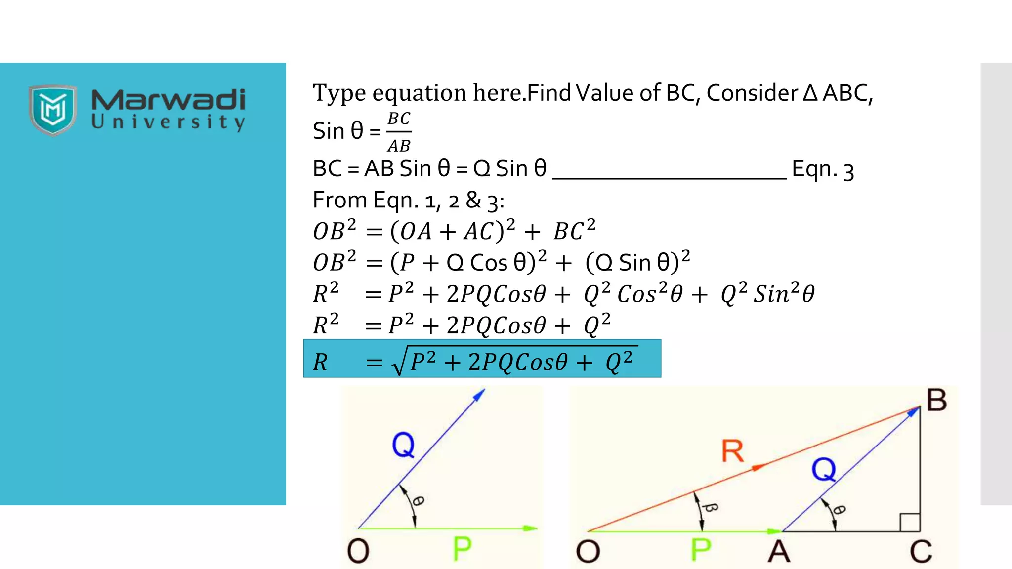
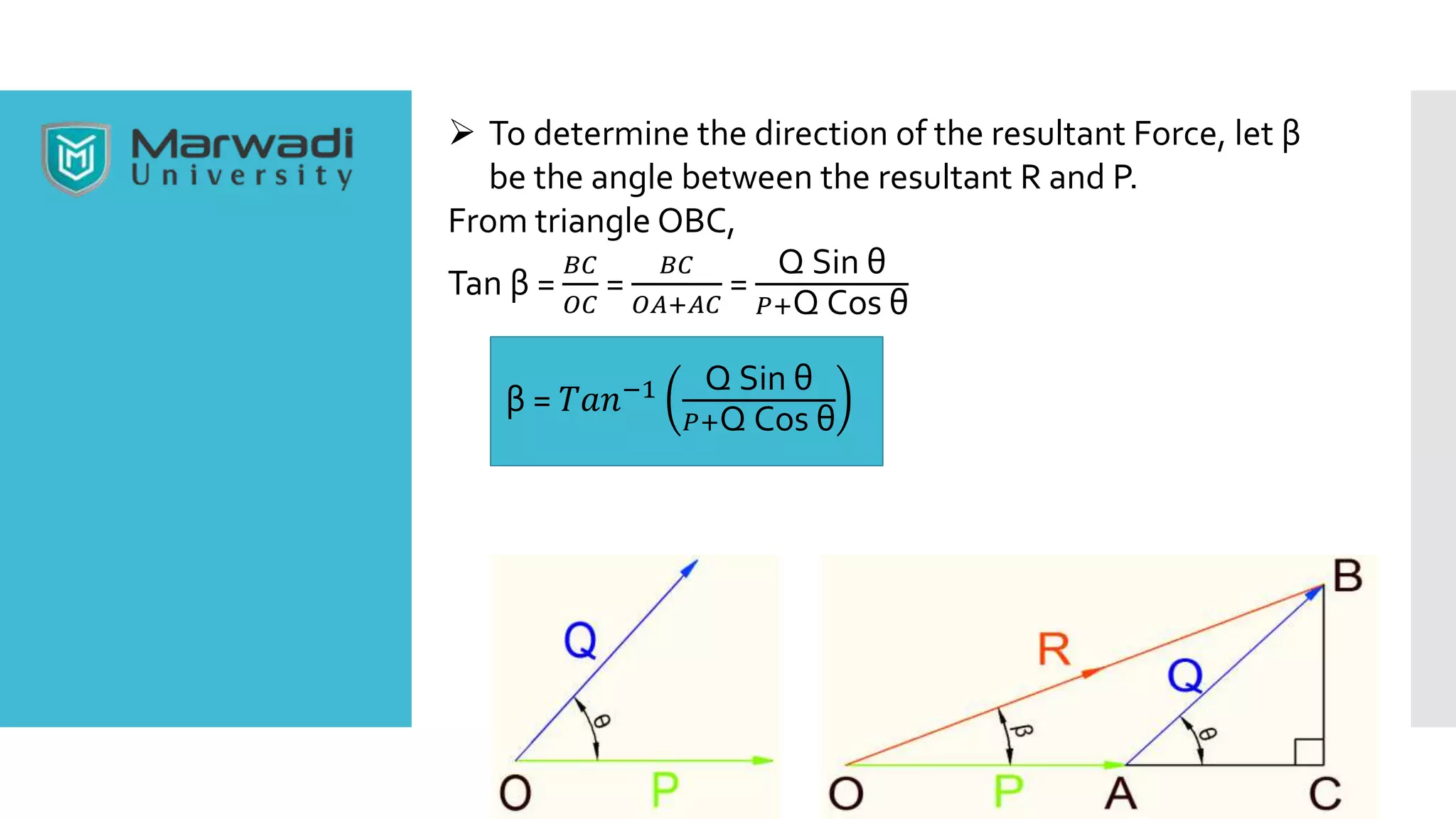
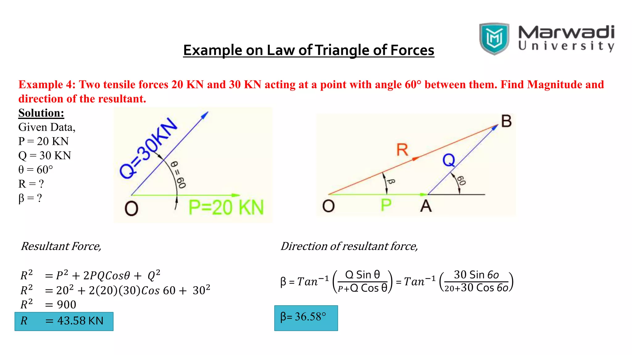
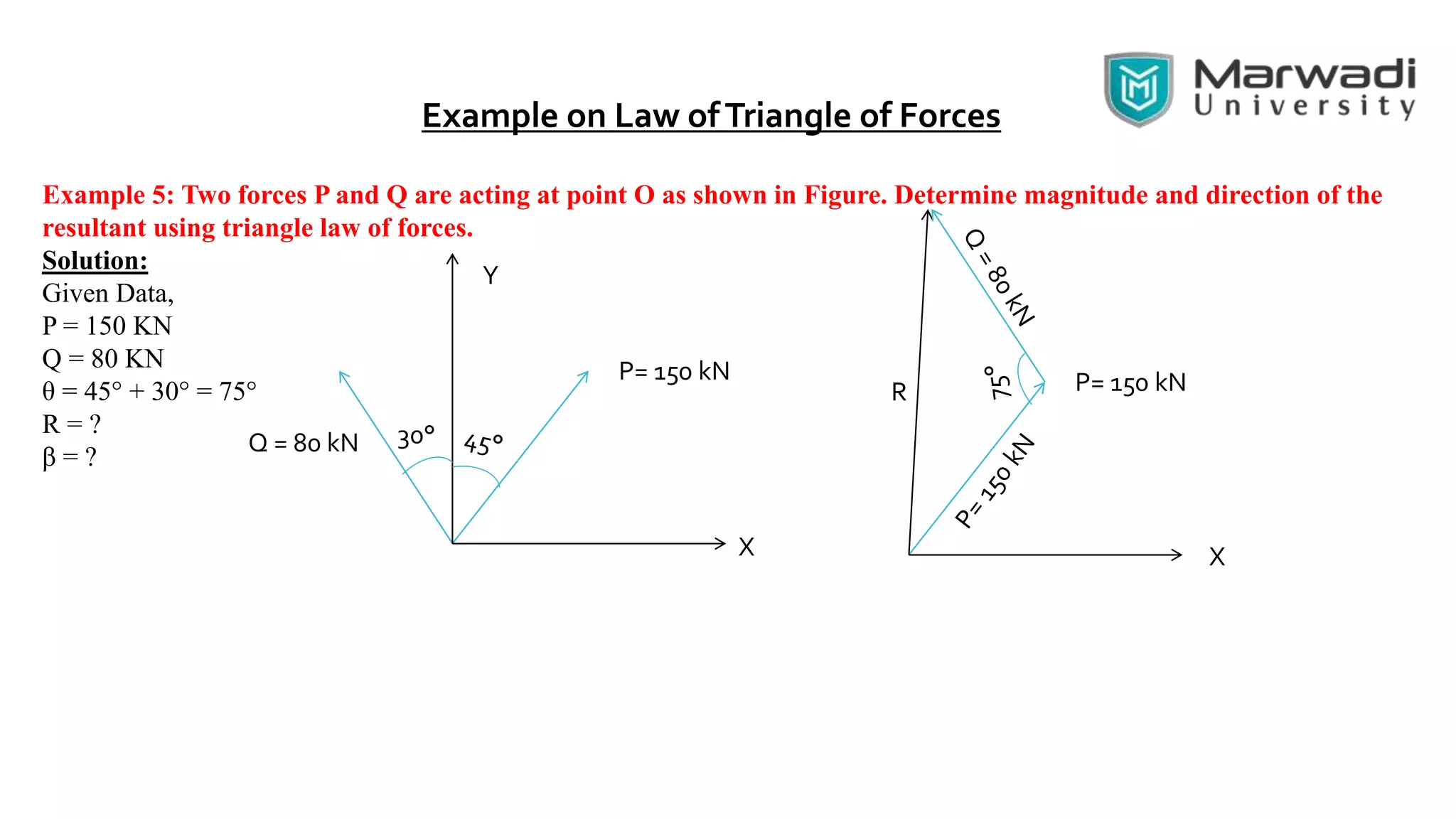
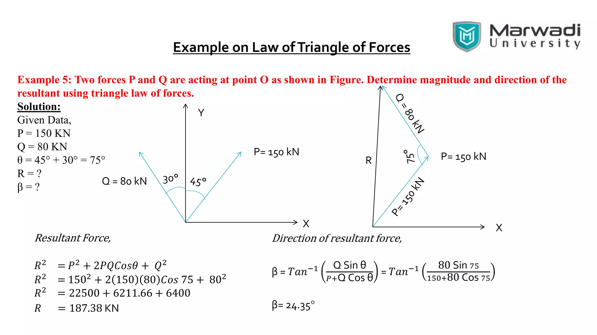
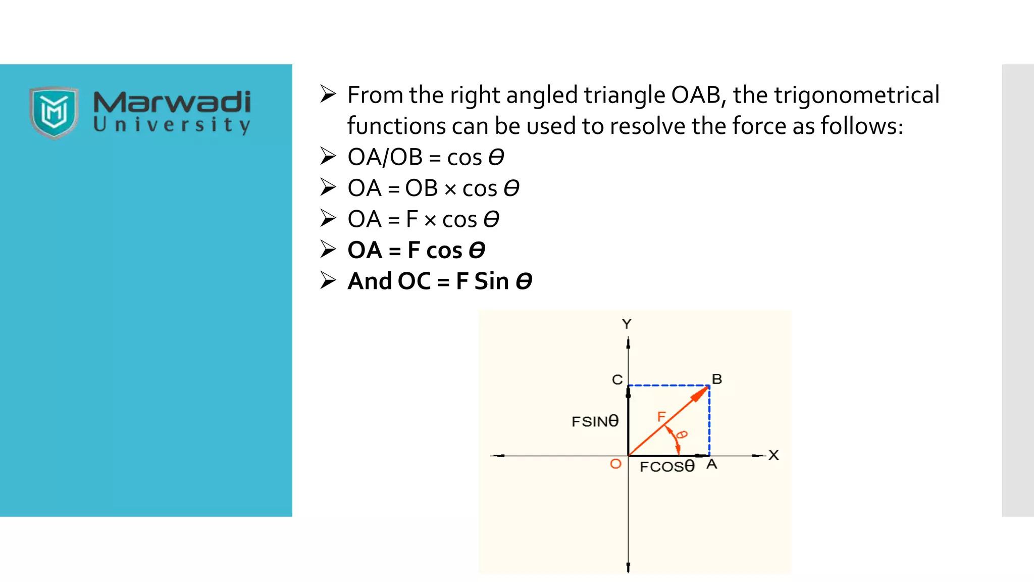
* Using the parallelogram law:
* R2 = P2 + Q2 + 2PQcosθ
* R2 = P2 + Q2 (since cos90° = 0)
* R2 = 10000 + Q2
* R = 100 kN
* Therefore, Q2 = R2 - P2
* Q2 = 10000 - 10000
* Q2 = 0
* Q = 0 kN
So if the two forces act at right angles to each other, and


![coplanarforce[1].pptx](https://cdn.slidesharecdn.com/ss_thumbnails/coplanarforce1-230224102654-6c44f1d2-thumbnail.jpg?width=640&height=640&fit=bounds)


