Downloaded 116 times
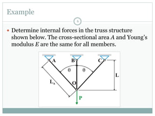
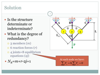
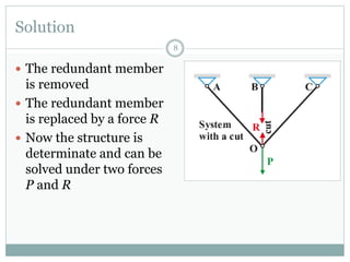
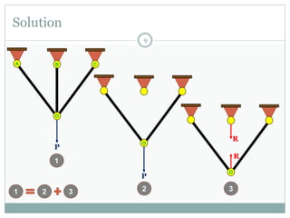
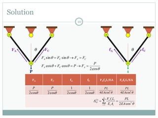
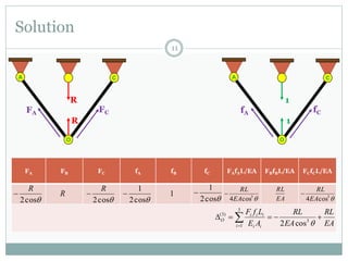
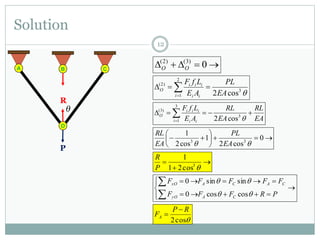
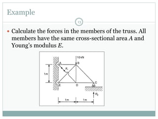
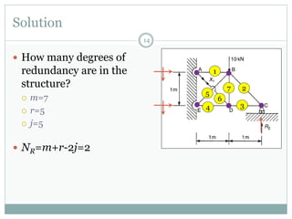
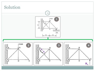
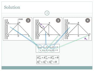
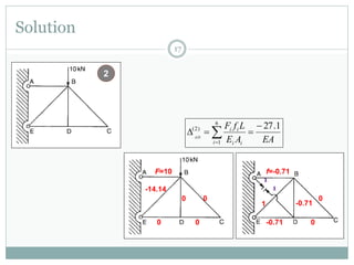
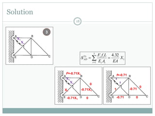
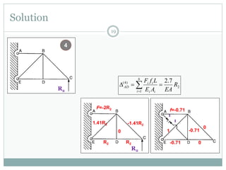
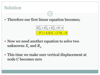
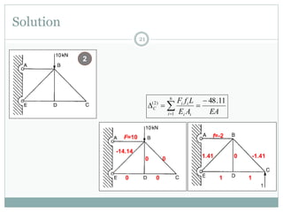
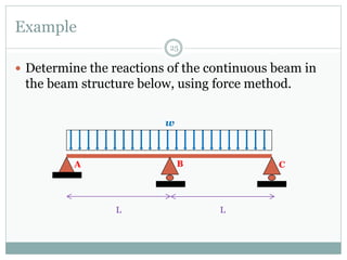
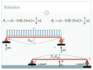
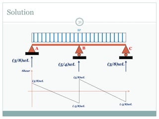
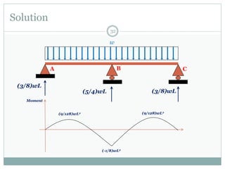
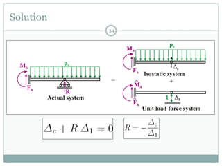
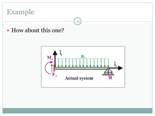
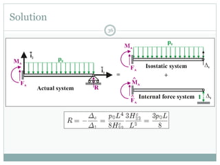
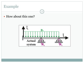
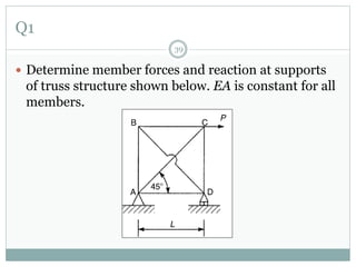
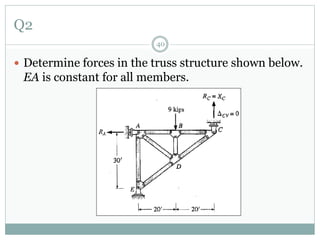
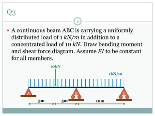
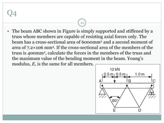
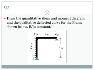

The first question asks to determine member forces in a provided truss structure using the force method. The second asks to do the same for a different truss. The third involves drawing bending moment and shear force diagrams for a continuous beam with distributed