- 6 -
פרק1–הקדמה
1.1קיצוריםרשימת
USB – Universal Serial Bus
RPM – Round Per Minute
VGA – Video Graphics Array
RoHS – Restriction of Hazardous Substances Directive
GUI – Graphical User Interface
RGB – Red Green Blue
EEPROM – Electrically Erasable Programmable Read Only Memory
UART – Universal Asynchronous Receiver Transmitter
PC – Personal Computer
DC – Direct Current
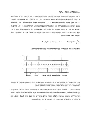
PWM – Pulse Width Modulation
FPGA – Field Programmable Gate Array
LED – Light Emitting Diode
CHT – Circular Hough Transform
SOC – System On Chip
VLSI – Very Large Scale Integration
ASIC – Application Specific Integrated Circuit
CCD – Charge Coupled Device
7.
- 7 -
VGA– Video Graphics Array
JPEG – Joint Photographic Experts Group
LCD – Liquid Crystal Display
LSB – Least Significant Bit
MSB – Most Significant Bit
FHSS – Frequency Hopping Spread Spectrum
PAN – Personal Area Network
ISM – Industrial Scientific and Medical
AFH – Adaptive Frequency Hopping Spread Spectrum
SPP – Serial Port Profile
MOSFET – Metal Oxide Semiconductor Field Effect Transistors
WiFi – Wireless Fidelity
IP – Internet Protocol
ISI – Intersymbol Interference
COM – Component Object Model
Ascii – American Standard Code For Information Interchange
VHSIC – Very High Speed Integrated Circuits
VHDL – VHSIC Hardware Description Language
RTL – Register Transfer Logic
- 9 -
1.3Abstract
These days, the field of computer vision is playing an increasingly growing part in the
technological front. In the industry we are witnessing automation of processes which were
shared by human operators in the past, such as tests, quality assurance of visual media,
Internet and digital videos. Security issues too, are being upgraded with techniques of image
processing and computer vision for the identification and tracking of people, faces and other
purposes. These techniques significantly improve the quality of the results and greatly reduce
costs.
This project's goal is to process computer vision products and their application, by using an
FPGA-controlled robot. This is done by a chain of processes that begin with real time video
footage taken with a Smartphone mounted on the robot and sent to a computer for processing.
The processing is done using Matlab software that identifies and classifies geometric objects
(scattered in the room where the robot is located), according to shape and color. The products
of this processing are then translated into commands which are transferred to the robot (with
wireless Bluetooth) using serial control media. The information is then broadcast to the
Bluetooth receiver on the robot and sent directly to the FPGA via UART that acts as a receiver
only and is synchronized with the transmission rate of information received from the
transmitter (The computer). The FPGA is used as a controller that is connected via I/O ports to
the robot’s wheels which run with Servo motors and to LED lights (green, red and yellow),
operating them according to the information processed.
The entire process is managed and controlled by a GUI application that was written in the
Matlab environment and with which the user can see the robot's movement from the camera
installed on it, in real-time. The user shares the interface with the robot through a serial port
selected by the user, hereby controlling the motion with dedicated controls and diagnosing
identification of the objects in the space.
- 22 -
2.9.3UARTב-PC
פרוטוקולUARTבנתמך-PCע"יציאה יטוריתRS-232המתאימה הקונפיגורציה את שעשינו בהנחה
לתקשורת.ביציאה הפינים פירוטהטוריתשלה-PC:
D-Type-9 Pin
No.
Abbreviation Full Name
Function
Pin 3 TD Transmit Data Serial Data Output (TXD)
Pin 2 RD Receive Data Serial Data Input (RXD)
Pin 7 RTS
Request To
Send
This line informs the Modem
that the UART is ready to
exchange data
Pin 8 CTS Clear To Send
This line indicates that the
Modem is ready to exchange
data
Pin 6 DSR Data Set Ready
This tells the UART that the
modem is ready to establish a
link.
Pin 5 SG Signal Ground
Pin 1 CD Carrier Detect
When the modem detects a
"Carrier" from the modem at
the other end of the phone
line, this Line becomes active.
Pin 4 DTR
Data Terminal
Ready
This is the opposite to DSR.
This tells the Modem that the
UART is ready to link.
Pin 9 RI Ring Indicator
Goes active when modem
detects a ringing signal from
the PSTN
טבלה12–ה של הטורית ביציאה הפינים פירוט-PC
- 30 -
פרק3–המערכתמבנה
“DroidCam” application
(through Wi-Fi)
Bluetooth
UART
איור25–המערכת כלל של זרימה תרשים
Graphical user
interface
User input Smartphone
camera
Bluetooth
modem
FPGA Continues
servo motor
LEDS