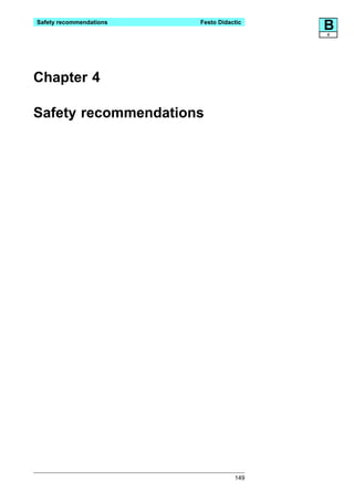
Downloaded 1,241 times

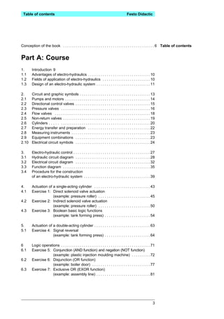
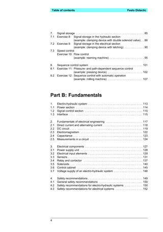


This document is a textbook on electro-hydraulics that is divided into three parts. Part A provides an introduction and covers topics like hydraulic and electrical symbols, basic electro-hydraulic control systems, and exercises involving actuating cylinders and logic operations. Part B covers fundamentals of electro-hydraulic systems, electrical engineering, components, and safety. Part C contains solutions to the exercises. The book aims to teach basic and applied electro-hydraulics through explanations, diagrams, and practical exercises.


